Table of Contents
Advertisement
Quick Links
This user's guide describes the characteristics, operation, and use of the TIC12400 Evaluation Module
(EVM).
...................................................................................................................
1
......................................................................................................................
2
3
4
5
TIC12400 GUI Application
..................................................................................................................
6
Board Files
1
TIC12400 EVM Block Level Diagram
2
TIC12400 EVM, SWITCH BOARD, and USB to USB-Mini Cable
3
EVM, SWITCH BOARD, USB Cable, PC, and Power Supply Setup
4
EVM Hardware Top Description
5
EVM Hardware Bottom Description
6
7
8
Figure 3. Installation Steps 7-13
9
10
11
12
13
Page Connections
.................................................................................................................
14
15
...................................................................................................................
16
<Caption>
17
18
SCPU036 - October 2017
Submit Documentation Feedback
.................................................................................
..................................................................................................
................................................................................................
.....................................................................................
...........................................................................................
......................................................................................
........................................................................................
......................................................................................................
.........................................................................................
............................................................................................................
...............................................................................................
..............................................................................................
..........................................................................................................
...............................................................................................................
................................................................................................
Copyright © 2017, Texas Instruments Incorporated
TIC12400 Evaluation Module
Contents
List of Figures
.....................................................
.................................................
...........................................................
...................................................................
User's Guide
SCPU036 - October 2017
TIC12400 Evaluation Module
2
4
8
11
14
39
2
4
4
5
6
11
12
13
14
14
17
21
39
40
41
41
41
42
1
Advertisement
Table of Contents

Related Manuals for Texas Instruments TIC12400


Summary of Contents for Texas Instruments TIC12400
-
Page 1: Table Of Contents
User's Guide SCPU036 – October 2017 TIC12400 Evaluation Module This user's guide describes the characteristics, operation, and use of the TIC12400 Evaluation Module (EVM). Contents ........................Introduction ........................Hardware ................. SWITCH BOARD Hardware Description ....................GUI Software Installation ....................TIC12400 GUI Application ........................ -
Page 2: Introduction
Introduction The TIC12400 is a multiple switch detection interface that is designed to detect the opening and closing of up to 24 switch contacts. 10 out of the 24 inputs are configurable to detect switch states that are either battery connected switches (BCS) or ground connected switches (GCS), which means it can either sink or source current from the channel. - Page 3 Do not touch. The DUT of the board can get hot when all channels are enabled at the highest wetting current settings in continuous mode SCPU036 – October 2017 TIC12400 Evaluation Module Submit Documentation Feedback Copyright © 2017, Texas Instruments Incorporated...
-
Page 4: Hardware
USB-MINI cable within the KIT; see Figure Figure 2. TIC12400 EVM, SWITCH BOARD, and USB to USB-Mini Cable Connection to the PC and Powering up the EVM A mini-USB cable is used to connect the EVM board to the PC. The VDD of the EVM is powered by the USB’s VBUS. - Page 5 Hardware www.ti.com EVM Hardware Description The TIC12400 EVM is designed to allow the user to easily evaluate switch detection using the GUI. The break down of all the features and design of the EVM follow. Required Circuitry Optional Circuitry or Functions Figure 4.
- Page 6 11. The filter capacitors at the pins of the device are not loaded by default and are there to allow the design of filters if needed. CONNECTOR 1,6,7,11,12 Figure 5. EVM Hardware Bottom Description TIC12400 Evaluation Module SCPU036 – October 2017 Submit Documentation Feedback Copyright © 2017, Texas Instruments Incorporated...
- Page 7 5. The TPS73533 receives power from the VBUS of the USB, which is 5 V. It then regulates that to the +3.3V output on the TIC12400 EVM. 6. There are two INA226A Current Monitors for measuring current in VDD (U12) and for measuring th current going into VS (U13).
-
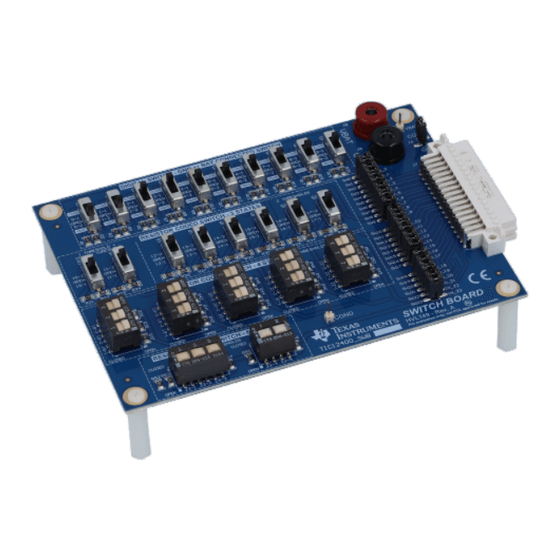
Page 8: Switch Board Hardware Description
5 thresholds, which means there are 6 states. Each switch represents one state and all switches in the “OPEN” position represents the 6th state. SW23_B SW23_A IN23 23-1 23-2 23-3 23-4 23-5 TIC12400 Evaluation Module SCPU036 – October 2017 Submit Documentation Feedback Copyright © 2017, Texas Instruments Incorporated... - Page 9 Each channel from 0 to 11, has one unique threshold mapping for each channel and one common threshold (THRES_COM) that is shared for all the channels (0-11). These switches are setup to illustrate this feature. OPEN OPEN OPEN OPEN SCPU036 – October 2017 TIC12400 Evaluation Module Submit Documentation Feedback Copyright © 2017, Texas Instruments Incorporated...
- Page 10 There are two state, “OPEN” and either chassis Ground Connected Switch (GCS) or Battery Connected Switch (BCS). VBAT OPEN OPEN OPEN IN_X OPEN TIC12400 Evaluation Module SCPU036 – October 2017 Submit Documentation Feedback Copyright © 2017, Texas Instruments Incorporated...
-
Page 11: Gui Software Installation
0.4.0_EVM.exe file to begin software installation or right click and select “Run as administrator”. The software will install two applications, “App Center” software and the TIC12400 GUI App software. If the “App Center” software isn’t already installed on the PC then additional steps will be needed. Those steps are outlines in the following figures. -
Page 12: Installation Steps
5. This screen should appear on top, unless the user clicks on another item. Sometimes the screen may appear to be behind the other setup screen. The TIC12400 EVM GUI will not install until the App Center software is first installed. -
Page 13: Figure 3. Installation Steps 7–13
Figure 8. Figure 3. Installation Steps 7–13 The EVM GUI can either be opened before or after the EVM is setup and power is applied. SCPU036 – October 2017 TIC12400 Evaluation Module Submit Documentation Feedback Copyright © 2017, Texas Instruments Incorporated... -
Page 14: Double Click On "App Center Evm Gui" Shortcut To Open
Figure 9. Double Click on “App Center EVM GUI” Shortcut to Open TIC12400 Info Page The “Info” page (Home) of the TIC12400 GUI has a short summary of the features of the TIC12400. See the following map of features of the “Info” page in Figure Figure 10. - Page 15 The settings button will open a sub menu for Channel Configurations, Device Settings and Matrix configuration. These are the same pages accessed by the men bar on the left side of the GUI. SCPU036 – October 2017 TIC12400 Evaluation Module Submit Documentation Feedback Copyright © 2017, Texas Instruments Incorporated...
- Page 16 If there is no communication with either the on board micro controller (MSP430) or the device then the following image will be seen, indicated no communication. TIC12400 Evaluation Module SCPU036 – October 2017 Submit Documentation Feedback Copyright © 2017, Texas Instruments Incorporated...
-
Page 17: Device Configuration Page
TIC12400 GUI Application www.ti.com Device Settings Page The Device Configuration page controls many of the features for TIC12400 that control device general operation. Figure 11. Device Configuration Page SCPU036 – October 2017 TIC12400 Evaluation Module Submit Documentation Feedback Copyright © 2017, Texas Instruments Incorporated... - Page 18 This button sends a software reset to the device via SPI. This will reset all registers to their default setting! The user must write back all the registers before selecting “Trigger” and to start wetting current and start external switch monitoring. TIC12400 Evaluation Module SCPU036 – October 2017 Submit Documentation Feedback Copyright © 2017, Texas Instruments Incorporated...
- Page 19 Temperature warning event occurs. The TIC12400 has the ability to do an ADC diagnostics and also has the ability to test wetting currents on IN0, IN1, IN2, and IN3 and diagnose if there are faults.
- Page 20 TIC12400 GUI Application www.ti.com The TIC12400's advanced settings have several features that allow the user to optimize their switch state change monitoring system. VS measurement can be enabled or disabled here. Once enabled the advanced settings menu becomes accessible to the right of the checkbox.
-
Page 21: Channel Configuration Page
Channels. Figure 12. Channel Configuration Page The TIC12400 has a variety of setting and features that are accessed and controlled by doing read and writes to the device. It is important to note that when selecting and changing setting within the GUI it must be written to the device prior to initiating the activation of the device by clicking on the “Trigger”... - Page 22 TIC12400 GUI Application www.ti.com The TIC12400 has 24 channels that can be configured a variety of ways to detect all types of switches. Within the “Simple View” the GUI breaks down each channel into manageable easy to visualize channel settings. In order to change the setting the Channel must be Enabled, which is done by clicking on the Enable/Disable button.
- Page 23 GUI, but it does clear the INT_STAT register within the device. All the Channels can be Enabled or Disabled all at once by clicking on these buttons. SCPU036 – October 2017 TIC12400 Evaluation Module Submit Documentation Feedback Copyright © 2017, Texas Instruments Incorporated...
- Page 24 TIC12400 GUI Application www.ti.com The TIC12400 Channel Configurations can be controlled by one of three ways. 1) "Simple View" is the default mode of accessing the Channel Configurations if 2) "Detailed View" allows the user to see all the Channel Configurations at once and also to design to show all the dependent variables.
- Page 25 Channel Configuration Wizard The TIC12400 GUI will walk through the system configuration with a series of question prompts on the system configuration. Once a prompt is completed the GUI will move on the to the next step. You can edit any prompt at any time regardless of your current step in the wizard.
- Page 26 Each IWett setting will give a recommended threshold. If the Recommended threshold in N/A that setting is not recommended. This displays the current global thresholds for the ADC. TIC12400 Evaluation Module SCPU036 – October 2017 Submit Documentation Feedback Copyright © 2017, Texas Instruments Incorporated...
- Page 27 TIC12400 is configured. After the desired settings are correct, clicking the copy settings will configure the TIC12400 device. Clicking Do Nothing will exit the wizard. The wizard can be used multiple times to update TIC12400 per each switch in the system.
- Page 28 Additionally the available threshold settings are Thres3A/B/C. These thresholds can be mapped to any unmapped thresholds but must follow the rules that ThresC > ThresB > ThresA. TIC12400 Evaluation Module SCPU036 – October 2017 Submit Documentation Feedback Copyright © 2017, Texas Instruments Incorporated...
- Page 29 Clicking the same button again will disable the GUI tracker. Note this does not enable/disable the channel in the device, it changes if the GUI displays any real time changes. SCPU036 – October 2017 TIC12400 Evaluation Module Submit Documentation Feedback Copyright © 2017, Texas Instruments Incorporated...
- Page 30 Trigger has been enabled in section 3. Clicking the trigger button will enable the device to monitor the inputs and update the real time status tracker. Matrix Configuration TIC12400 Evaluation Module SCPU036 – October 2017 Submit Documentation Feedback Copyright © 2017, Texas Instruments Incorporated...
- Page 31 The detection edge control option lets you select between no detection, rising, falling, and rising or falling edge detection schemes. The Matrix polling active time controls how long the inputs are polled as described in the datasheet. SCPU036 – October 2017 TIC12400 Evaluation Module Submit Documentation Feedback Copyright © 2017, Texas Instruments Incorporated...
- Page 32 (4x4, 5x5, 6x6) will change the image to show which channels are being used. After setting the desired matrix configuration click the Write to Device button to set the register settings in the TIC12400 device. Use the Trigger button to monitor the TIC12400 enable monitoring of the inputs.
- Page 33 Matrix mode calculations can be enabled by clicking the checkbox. This will open up a menu to select the matrix configuration options. The Polling_Act_Time and Polling time can be selected as well. SCPU036 – October 2017 TIC12400 Evaluation Module Submit Documentation Feedback Copyright © 2017, Texas Instruments Incorporated...
- Page 34 Clicking calculate will prompt the results page which will deliver the measurement cycle time, active duty cycle and the effective current for different temperatures. TIC12400 Evaluation Module SCPU036 – October 2017 Submit Documentation Feedback Copyright © 2017, Texas Instruments Incorporated...
- Page 35 After matrix mode is checked the boxes become interactive. Clicking different switches will close or open them and the current calculator will update accordingly. SCPU036 – October 2017 TIC12400 Evaluation Module Submit Documentation Feedback Copyright © 2017, Texas Instruments Incorporated...
- Page 36 Write Register button is clicked. If Auto Read is enable, any register changes that have not been sent to the device will be overwritten to the current value of the TIC12400. The bit field representation will also update as the value field of the register is adjusted.
- Page 37 Clicking the red x will exit the help menu for that register and take the user back to the register fields. SCPU036 – October 2017 TIC12400 Evaluation Module Submit Documentation Feedback Copyright © 2017, Texas Instruments Incorporated...
- Page 38 The deferred setting will wait for the user to click the Write Register button before sending the new register settings to the device. TIC12400 Evaluation Module SCPU036 – October 2017 Submit Documentation Feedback Copyright © 2017, Texas Instruments Incorporated...
- Page 39 IN0_SB IN6_SB IN1_SB IN5_SB PEC24SAAN IN4_SB Hardware IN2_SB HVL129A_Hardware IN3_SB 5650478-5 Power Supplies HVL129A_PowerSupply Copyright © 2017, Texas Instruments Incorporated Figure 13. Page Connections SCPU036 – October 2017 TIC12400 Evaluation Module Submit Documentation Feedback Copyright © 2017, Texas Instruments Incorporated...
-
Page 40: Main Device
0.01µF CSD17313Q2 HVL129A_INx.SchDoc IN14 SB_IN_ HVL129A_INx.SchDoc 0.01µF IN23 SB_IN_ 0.01µF HVL129A_INx.SchDoc IN15 SB_IN_ 0.01µF Copyright © 2017, Texas Instruments Incorporated Figure 14. Main Device TIC12400 Evaluation Module SCPU036 – October 2017 Submit Documentation Feedback Copyright © 2017, Texas Instruments Incorporated... -
Page 41: Usb Interface
SCLBRD ADD0 AVCC1 AVSS2 DVCC1 DVSS1 ALERT DVCC2 DVSS2 MSP430F5529IPNR TMP102AQDRLRQ1 0.1µF 0.1µF 0.1µF Copyright © 2017, Texas Instruments Incorporated Figure 15. USB interface +VBUS SH-J1 +3.3V TPS 7A6550QKVURQ1 VOUT 0.1µF 2.2µF SH-J7 12V Battery Input Vbat_c VBAT_MSDI 600 ohm... -
Page 42: Switch Board Schematic
23-2 23-3 23-4 23-5 IN4_SB CGND CGND CGND CGND CGND CGND CGND IN3_SB Copyright © 2017, Texas Instruments Incorporated Figure 18. SWITCH Board Schematic TIC12400 Evaluation Module SCPU036 – October 2017 Submit Documentation Feedback Copyright © 2017, Texas Instruments Incorporated... - Page 43 Standoff, Hex, 1"L #4-40 Nylon Standoff 1902E H3, H6, H9, H12 Machine Screw, Round, #4-40 x 1/4, Nylon, Philips panhead Screw NY PMS 440 0025 PH SCPU036 – October 2017 TIC12400 Evaluation Module Submit Documentation Feedback Copyright © 2017, Texas Instruments Incorporated...
- Page 44 RES, 1.62 k, 1%, 0.1 W, 0603 0603 CRCW06031K62FKEA 5.10k RES, 5.10 k, 1%, 0.1 W, 0603 0603 RC0603FR-075K1L Switch, Tactile, SPST-NO, SMT Switch, 6.1x1.8x4.6 mm EVQ-PSD02K TIC12400 Evaluation Module SCPU036 – October 2017 Submit Documentation Feedback Copyright © 2017, Texas Instruments Incorporated...
- Page 45 Low-Power Digital Temperature Sensor With SMBus and Two-Wire Serial Interface in SOT563, DRL0006A TMP102AQDRLRQ1 DRL0006A U12, U13 High-or Low-Side Measurement, Bi-Directional CURRENT/POWER MONITOR with I2C(TM) DGS0010A INA226AIDGSR Interface, DGS0010A SCPU036 – October 2017 TIC12400 Evaluation Module Submit Documentation Feedback Copyright © 2017, Texas Instruments Incorporated...
- Page 46 RES, 402, 1%, 0.25 W, 1206 1206 ERJ-8ENF4020V RES, 887, 1%, 0.25 W, 1206 1206 ERJ-8ENF8870V 1.65k RES, 1.65 k, 1%, 0.25 W, 1206 1206 ERJ-8ENF1651V TIC12400 Evaluation Module SCPU036 – October 2017 Submit Documentation Feedback Copyright © 2017, Texas Instruments Incorporated...
- Page 47 SW23_B Switch, DPST, 2 Pos, 0.1 A, 50 VDC, SMD 12.34x9.78mm 204-212ST FID1, FID2, FID3 Fiducial mark. There is nothing to buy or mount. SCPU036 – October 2017 TIC12400 Evaluation Module Submit Documentation Feedback Copyright © 2017, Texas Instruments Incorporated...
- Page 48 STANDARD TERMS FOR EVALUATION MODULES Delivery: TI delivers TI evaluation boards, kits, or modules, including any accompanying demonstration software, components, and/or documentation which may be provided together or separately (collectively, an “EVM” or “EVMs”) to the User (“User”) in accordance with the terms set forth herein.
- Page 49 FCC Interference Statement for Class B EVM devices NOTE: This equipment has been tested and found to comply with the limits for a Class B digital device, pursuant to part 15 of the FCC Rules. These limits are designed to provide reasonable protection against harmful interference in a residential installation.
- Page 50 【無線電波を送信する製品の開発キットをお使いになる際の注意事項】 開発キットの中には技術基準適合証明を受けて いないものがあります。 技術適合証明を受けていないもののご使用に際しては、電波法遵守のため、以下のいずれかの 措置を取っていただく必要がありますのでご注意ください。 1. 電波法施行規則第6条第1項第1号に基づく平成18年3月28日総務省告示第173号で定められた電波暗室等の試験設備でご使用 いただく。 2. 実験局の免許を取得後ご使用いただく。 3. 技術基準適合証明を取得後ご使用いただく。 なお、本製品は、上記の「ご使用にあたっての注意」を譲渡先、移転先に通知しない限り、譲渡、移転できないものとします。 上記を遵守頂けない場合は、電波法の罰則が適用される可能性があることをご留意ください。 日本テキサス・イ ンスツルメンツ株式会社 東京都新宿区西新宿6丁目24番1号 西新宿三井ビル 3.3.3 Notice for EVMs for Power Line Communication: Please see http://www.tij.co.jp/lsds/ti_ja/general/eStore/notice_02.page 電力線搬送波通信についての開発キットをお使いになる際の注意事項については、次のところをご覧ください。http:/ /www.tij.co.jp/lsds/ti_ja/general/eStore/notice_02.page 3.4 European Union 3.4.1 For EVMs subject to EU Directive 2014/30/EU (Electromagnetic Compatibility Directive): This is a class A product intended for use in environments other than domestic environments that are connected to a low-voltage power-supply network that supplies buildings used for domestic purposes.
- Page 51 Notwithstanding the foregoing, any judgment may be enforced in any United States or foreign court, and TI may seek injunctive relief in any United States or foreign court. Mailing Address: Texas Instruments, Post Office Box 655303, Dallas, Texas 75265 Copyright © 2017, Texas Instruments Incorporated...
- Page 52 IMPORTANT NOTICE FOR TI DESIGN INFORMATION AND RESOURCES Texas Instruments Incorporated (‘TI”) technical, application or other design advice, services or information, including, but not limited to, reference designs and materials relating to evaluation modules, (collectively, “TI Resources”) are intended to assist designers who are developing applications that incorporate TI products;...
Need help?
Do you have a question about the TIC12400 and is the answer not in the manual?
Questions and answers