Table of Contents
Advertisement
Quick Links
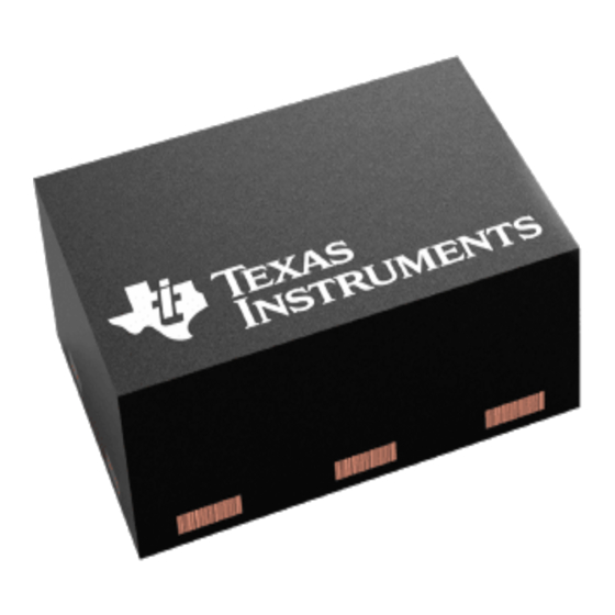
TPS62730 Stepdown Converter With Bypass Mode for
This user's guide describes the TPS62730 evaluation module (EVM), how to perform a stand-alone
evaluation or interface with a host or system. The converter is designed to deliver up to 100 mA of
continuous current to the output. The converter can be switched into bypass mode by grounding the
ON/BYP pin or automatically with the input voltage falling to the output regulation voltage.
1
2
3
4
4.1
4.2
4.3
5
5.1
5.2
5.3
6
1
2
3
....................................................................................................................
4
5
6
7
8
9
10
11
12
13
14
SLVU455 - April 2011
Submit Documentation Feedback
Ultralow-Power Wireless Applications
..................................................................................................................
.....................................................................................
...............................................................................................................
...........................................................................................................
.......................................................................................
...........................................................................................................
...................................................................................................
.....................................................................................................
........................................................................................................
...................................................................................
........................................................................................
.............................................................................................................
................................................................................................................
..............................................................................................................
TPS62730 Stepdown Converter With Bypass Mode for Ultralow-Power Wireless
Copyright © 2011, Texas Instruments Incorporated
Contents
.........................................................................
............................................................
.....................................................................
List of Figures
......................................................
.....................................................................
.................................................................
.................................................................
User's Guide
SLVU455 - April 2011
..................................
....................................
..........................
........................
Applications
2
2
2
2
3
3
4
5
5
5
7
7
3
5
5
6
6
7
8
8
9
9
10
10
11
11
1
Advertisement
Table of Contents

Summary of Contents for Texas Instruments TPS62730
-
Page 1: Table Of Contents
TPS62730 Stepdown Converter With Bypass Mode for Ultralow-Power Wireless Applications This user’s guide describes the TPS62730 evaluation module (EVM), how to perform a stand-alone evaluation or interface with a host or system. The converter is designed to deliver up to 100 mA of continuous current to the output. -
Page 2: Introduction
Li-ion primary battery chemistries, with an input range of 1.9 V to 3.9 V dc. The TPS62730 features an ultralow-power bypass mode with a typical 30 nA current consumption to support low-power modes of modern RF transceivers. In this bypass mode, the input is connected the VOUT pin via an internal 2-Ω... -
Page 3: Equipment
Three Fluke 75 DMMs (equivalent or better) • Oscilloscope, model TDS222 (equivalent or better) Equipment and EVM Setup Table 1. Setup I/O Connections and Configuration for Evaluation of TPS62730 EVM Jack/Component (Silk Screen) Connect or Adjustment To: J1-1/2 (Vin) Power supply positive lead, preset to 3.3 VDC, 150-mA current limit J2-1 (+ SNS);... -
Page 4: Test Procedure Using A Single Cell Li-Ion Battery
50 mA to 100 mA. 13. See Figure 14 for the transient output load step from 100 mA to 50 mA. SLVU455 – April 2011 TPS62730 Stepdown Converter With Bypass Mode for Ultralow-Power Wireless Applications Submit Documentation Feedback Copyright © 2011, Texas Instruments Incorporated... -
Page 5: Schematic, Physical Layouts And Bill Of Materials
Schematic, Physical Layouts and Bill of Materials Schematic S002 Figure 2. TPS62730 EVM Board Schematic Physical Layouts K001 Figure 3. Assembly Layer SLVU455 – April 2011 TPS62730 Stepdown Converter With Bypass Mode for Ultralow-Power Wireless Applications Submit Documentation Feedback Copyright © 2011, Texas Instruments Incorporated... -
Page 6: Top Layer
Schematic, Physical Layouts and Bill of Materials www.ti.com K002 Figure 4. Top Layer K003 Figure 5. Bottom Layer SLVU455 – April 2011 TPS62730 Stepdown Converter With Bypass Mode for Ultralow-Power Wireless Applications Submit Documentation Feedback Copyright © 2011, Texas Instruments Incorporated... -
Page 7: Bill Of Materials
Oscilloscope Traces G001 Figure 6. CH1: Phase; CH2: Output Ripple, Vin = 3.3 V, and 21-Ω Load SLVU455 – April 2011 TPS62730 Stepdown Converter With Bypass Mode for Ultralow-Power Wireless Applications Submit Documentation Feedback Copyright © 2011, Texas Instruments Incorporated... -
Page 8: Pfm Mode At Low Load, 40 Ma - Ch1: Phase; Ch2: Output Ripple; 0.2 Μs/Div
G003 Figure 8. PFM Mode at Low Load, 11 mA – CH1: Phase; CH2: Output Ripple; 1 µs/div SLVU455 – April 2011 TPS62730 Stepdown Converter With Bypass Mode for Ultralow-Power Wireless Applications Submit Documentation Feedback Copyright © 2011, Texas Instruments Incorporated... -
Page 9: Transition From Switching Converter To Bypass Mode By Removing Input Power - Ch1: Phase Node; Ch2: Stat Pin
Node; CH2: STAT Pin G005 Figure 10. Transition From Converter Switch Mode to Bypass Mode by Pulling ON/BYP Pin Low SLVU455 – April 2011 TPS62730 Stepdown Converter With Bypass Mode for Ultralow-Power Wireless Applications Submit Documentation Feedback Copyright © 2011, Texas Instruments Incorporated... -
Page 10: Transition From Bypass Mode To Converter Switch Mode By Pulling On/Byp Pin High
Figure 11. Transition From Bypass Mode to Converter Switch Mode by Pulling ON/BYP Pin High G007 Figure 12. Startup by Hot-Plugging the Input Power Source SLVU455 – April 2011 TPS62730 Stepdown Converter With Bypass Mode for Ultralow-Power Wireless Applications Submit Documentation Feedback Copyright © 2011, Texas Instruments Incorporated... -
Page 11: Transient Output Load Step From 50 Ma To 100 Ma
Figure 13. Transient Output Load Step From 50 mA to 100 mA G009 Figure 14. Transient Output Load Step From 100 mA to 50 mA SLVU455 – April 2011 TPS62730 Stepdown Converter With Bypass Mode for Ultralow-Power Wireless Applications Submit Documentation Feedback Copyright © 2011, Texas Instruments Incorporated... - Page 12 EVALUATION BOARD/KIT IMPORTANT NOTICE Texas Instruments (TI) provides the enclosed product(s) under the following conditions: This evaluation board/kit is intended for use for ENGINEERING DEVELOPMENT, DEMONSTRATION, OR EVALUATION PURPOSES ONLY and is not considered by TI to be a finished end-product fit for general consumer use. Persons handling the product(s) must have electronics training and observe good engineering practice standards.
- Page 13 IMPORTANT NOTICE Texas Instruments Incorporated and its subsidiaries (TI) reserve the right to make corrections, modifications, enhancements, improvements, and other changes to its products and services at any time and to discontinue any product or service without notice. Customers should obtain the latest relevant information before placing orders and should verify that such information is current and complete.


Need help?
Do you have a question about the TPS62730 and is the answer not in the manual?
Questions and answers