Table of Contents
Advertisement
Quick Links
Advertisement
Table of Contents

Related Manuals for Westermo Viper 108


Summary of Contents for Westermo Viper 108
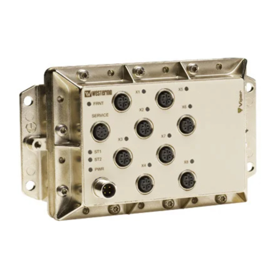
- Page 1 Viper 108 and 408 Managed 8-port Ethernet Switch...
- Page 2 6641-2201...
-
Page 3: General Information
Under no circumstances shall Westermo be responsible for any loss of data or income or any special, incidental, and consequential or indirect damages howsoever caused. -
Page 4: Safety Information
Safety information Before installation: Read this manual completely and gather all information on the unit. Make sure that you understand it fully. Check that your application does not exceed the safe operating specifications for this unit. This unit should only be installed by qualified personnel. This unit should be built-in to an apparatus cabinet, or similar, where access is restricted to service personnel only. -
Page 5: Care Recommendations
… Do not cover or bring mechanical force to the ventilation membrane on the back of the unit. If the unit is not working properly, contact the place of purchase, nearest Westermo distributor office or Westermo Tech support. Maintenance No maintenance is required, as long as the unit is used as intended within the specified conditions. -
Page 6: Simplified Eu Declaration Of Conformity
Simplified EU declaration of conformity Hereby, Westermo declares that the equipment is in compliance with EU directives. The full EU declaration of conformity and other detailed information are available at the respective product page at www.westermo.com. . Agency approvals and standards compliance... -
Page 7: Type Tests And Environmental Conditions
Type tests and environmental conditions Phenomena Test Description Test levels EN 61000-4-2 Enclosure contact ± 6 kV (crit A) Enclosure air ± 8 kV (crit A) RF field AM modulated IEC 61000-4-3 Enclosure 20 V/m 80% AM (1 kHz), 80 – 2700 MHz (crit A) 10 V/m 80% AM (1 kHz), 2700 –... - Page 8 Phenomena Test Description Test levels Shock, half sine pulses IEC 60068-2-27, Operating Vertical: 50 m/s Cat. 1 class B Transverse: 50 m/s (EN 61373) Longitudinal: 50 m/s 30 ms, 3 x 6 shocks Shock, sawtooth IEC 60068-2-27, Operating Vertical: 100 m/s Cat.
- Page 9 Description Functional description Viper is a range of switches consisting of two different function levels developed for rail and industrial applications. To meet the environmental requirements from rail and harsh industrial applications the switch has rugged M12 Ethernet connectors and full metal housing.
-
Page 10: Interface Specifications
Interface specifications Power and fault relay port PWR Rated voltage 24 to 110 VDC Operating voltage 16.8 to 143 VDC (14.4 to 154 for 100 ms) Rated current 140 mA @ 24 VDC 40 mA @ 110 VDC Rated frequency Inrush current, I Max 0.02 A s @ 24 –... -
Page 11: Fault Contact
To logic input +24/48 VDC Viper Viper 1 kΩ Input on PLC Service port The Service Port should not be used by non other than the Westermo Technical Support team. Do not connect any device or cable to the Service Port. 6641-2201... - Page 12 Ethernet TX port X1 to X8 Electrical specification IEEE std 802.3. 2000 Edition Data rate 10 Mbit/s or 100 Mbit/s, manual or auto Duplex Full or half, manual or auto Circuit type TNV-1 Transmission range 150 m Isolation to Other Ethernet ports, 500 VAC PWR, 1500 VAC Galvanic connection to None, except for shielded contact to housing...
- Page 13 Location of Interface ports, LED's LED indicators Status Description GREEN Unit indicates no fault Unit indicated fault FLASH Connected to IP Configuration tool FRNT FRNT is not enabled or not supported GREEN FRNT is running and the switch is configured as member switch in the ring.
- Page 14 The units can easily be configured via the ononard Web based configuration tool. Local IP addresses can also be configured by usinn the Westermo IP Configuration tool, from the IP Configuration tool it is then Enssible to browse into the unit fnr further configuration.
- Page 15 By clicking the “Scan for Devices” button the IP Configuration tool will detect the switches/routers in the network. The software will list all Westermo managed switches or routers connected to the network. Information as in the figure 1 will appear for each detected unit connected to the same network as your PC.
- Page 16 Log in via Web Westermo - location - Provided by Westermo UK http://192.168.2.200/conf/p.cgi Google You will be prompted with a Login screen where File Edit View Favorites Tools Help the default settings for Username and Password are: Home Feeds (J)
- Page 17 Mounting There are four 6 mm bore holes intended for mounting the unit. The unit can be mount- ed vertical or horizontal. The unit is wall mounted. FRNT SERVICE Removal Disconnect all cables and unscrew the unit from the wall. Cooling This unit uses convection cooling.
-
Page 18: Factory Reset
• All Ethernet ports are enabled and set to Auto Negotiate • All applications are disabled • Password reset to westermo To perform a Factory Reset follow the procedure below. Read all steps before starting. If you have any doubts whether the reset is performed or not, do NOT unplug the power supply, wait for confirmation according to step 5. - Page 19 Dimensions Measurements are stated in millimeters. 175 ±1 53,4 ±1 164 ±1 41,5 ±1 142 ±1 22,7 ±1 3,9 ±0,3 6,5 ±0,2(4x) 55,6 37,2 18,8 6641-2201...
- Page 20 Westermo • SE-640 40 Stora Sundby, Sweden Tel +46 16 42 80 00 Fax +46 16 42 80 01 E-mail: info@westermo.com www.westermo.com REV. K 6641-2201 2019-01 Westermo Network Technologies AB, Sweden...
Need help?
Do you have a question about the Viper 108 and is the answer not in the manual?
Questions and answers