
Related Manuals for INVT Photovoltaic Grid-connected Inverter


Summary of Contents for INVT Photovoltaic Grid-connected Inverter
- Page 1 Operation Manual Photovoltaic Grid-connected Inverter INVT Solar Technology (Shenzhen) Co., Ltd.
-
Page 3: Preface
Preface The manual is intended to provide detailed information of product information, installation, application, trouble shooting, precautions and maintenance of iMars series grid-tied solar inverters. The manual does not contain all the information of the photovoltaic system. Please read this manual carefully and follow all safety precautions seriously before any moving, installation, operation and maintenance to ensure correct use and high performance of operation on the inverter. -
Page 4: Table Of Contents
Three-phase photovoltaic grid-connected inverter Content Content Preface ..............................1 Content ............................... 2 1 Safety precautions ......................... 4 1.1 Warning marks............................5 1.2 Safety guidance ............................6 1.2.1 Transport and installation......................6 1.2.2 Grid-connected operation ......................7 1.2.3 Maintenance and inspection......................8 1.2.4 Waste disposal ..........................8 2 Product overview ........................... - Page 5 Three-phase photovoltaic grid-connected inverter Content 5.1 Inspection before running........................34 5.2 Inverter grid-connected running ......................34 5.3 Inverter stop ............................35 5.4 Daily maintenance and inspection ....................35 5.4.1 Periodic maintenance on the inverter..................36 5.4.2 Maintenance guidance ......................37 6 Display operation panel.......................
-
Page 6: Safety Precautions
Three-phase photovoltaic grid-connected inverter Safety precautions 1 Safety precautions iMars series grid-tied solar inverters are designed and tested strictly in accordance with relevant international safety standards. As an electrical and electronic device, all relevant safety regulations must be strictly complied during installation, operation, and maintenance. Incorrect use or misuse may result in:... -
Page 7: Warning Marks
Three-phase photovoltaic grid-connected inverter Safety precautions 1.1 Warning marks Warning marks inform users of conditions which can cause serious physical injury or death, or damage to the device. They also tell users how to prevent the dangers. The warning marks used in... -
Page 8: Safety Guidance
Three-phase photovoltaic grid-connected inverter Safety precautions 1.2 Safety guidance After receiving this product, first confirm the product package is intact. If any question, contact the logistic company or local distributor immediately. The installation and operation of PV inverter must be carried out by professional... -
Page 9: Grid-Connected Operation
Three-phase photovoltaic grid-connected inverter Safety precautions mechanical protective measures such as wearing anti-drop shoes or working clothes to protect physical security. The inverter must be installed by professional technicians. Do not store or install the inverter on flammable and combustible objects; keep the inverter away from flammable and combustible objects. -
Page 10: Maintenance And Inspection
Three-phase photovoltaic grid-connected inverter Safety precautions 1.2.3 Maintenance and inspection The maintenance, inspection and repair of the inverter must be done by well trained and qualified professional technicians. Contact distributors and manufactures for repair of the inverter. In order to avoid irrelevant personnel from entering the maintenance area during maintenance, temporary warning labels must be placed to warn non-professionals to enter or use fence for isolation. -
Page 11: Product Overview
Three-phase photovoltaic grid-connected inverter Product overview 2 Product overview This chapter mainly describes the appearance, package accessories, nameplate and technical parameters of the grid-connected inverter. -
Page 12: Pv Grid-Connected Power Generation System
AC current which has the same frequency and phase position with the public grid via photovoltaic grid-connected inverter, and feedback such energy to the grid. It is recommended that the PV array to be installed conforms to IEC 61730 class A standards. -
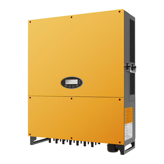
Page 13: Product Appearance
Three-phase photovoltaic grid-connected inverter Product overview Figure 2.2 Type of grid 2.2 Product appearance Fig 2.3 Appearance of 40-70kW three-phase PV inverter Table 2-1 Instruction for key cosmetic parts of three-phase PV inverter... - Page 14 Three-phase photovoltaic grid-connected inverter Product overview Name Instruction Display operation panel LED state indicator Surface cover DC input interface Inverter DC input port, connect to PV array Communication RS485 communication interface and its extension port EXT interface AC terminal Inverter AC output port, connect to public grid...
-
Page 15: Nameplate
Three-phase photovoltaic grid-connected inverter Product overview 2.3 Nameplate Figure 2.4 shows the inverter nameplate. Figure 2.4 Inverter nameplate (1)Trademark and product type (2)Model and important technical parameters (3)Certification system of the inverter confirming (4)Serial number, company name and country of origin... -
Page 16: Product Model
Table 2-3 Models of three-phase PV grid-connected inverter Rated output power Product name Model three-phase(L1, L2, L3, N, PE) three-phase photovoltaic grid-connected inverter 40kW 40kW three -phase photovoltaic grid-connected inverter 50kW 50kW three -phase photovoltaic grid-connected inverter 60kW 60kW three -phase photovoltaic grid-connected inverter 70kW... -
Page 17: Outline Dimension And Weight
Three-phase photovoltaic grid-connected inverter Product overview 2.5 Outline dimension and weight Fig 2.6 Outline dimension of the inverter Table 2-4 Dimension and net weight of the inverter Model Height(mm) Width(mm) Depth(mm) Net weight(kg) 40-70kW 70kW -HV 50kW-HV Fig 2.6 Dimension of paper package... -
Page 18: Storage
Three-phase photovoltaic grid-connected inverter Storage 3 Storage If the inverter is not put into use immediately, the storage of inverter should meet the following requirements: Do not remove the outer packing. The inverter needs to be stored in a clean and dry place, and prevent the erosion of dust and water vapor. -
Page 19: Installation
Installation Three-phase photovoltaic grid-connected inverter 4 Installation This chapter describes how to install the inverter and connect it to the grid-tied solar system (including the connection between solar modules, public grid and inverter). Read this chapter carefully and ensure all installation requirements are met before installation. Only... -
Page 20: Unpacking Confirmation
Installation Three-phase photovoltaic grid-connected inverter 4.1 Unpacking confirmation The inverter has been thoroughly tested and rigorously checked before delivery, but damage may still occur during transportation. Before unpacking, check carefully whether the product information in the order is consistent with that on the nameplate of the package box and whether the product package is intact. -
Page 21: Preparation Before Installation
Installation Three-phase photovoltaic grid-connected inverter Table 4-1 Deliverables of three-phase inverter Name Quantity Inverter Installation bracket Punch positioning plate User manual Communication connector 40KW:8pairs,50KW:10 pairs, 60/70KW:14 pairs DC connector Expansion bolt M8*60 Hex combination bolt M8*20 Combination bolt M5*20 AC ring terminal Check above-mentioned items carefully and if any question, contact the supplier immediately. -
Page 22: Installation Site
Installation Three-phase photovoltaic grid-connected inverter 4.2.2 Installation site Select installation site according to below requirements: The height of the installation position should ensure that the line of sight is on the same level as the LCD for viewing the parameters inverter conveniently. - Page 23 Installation Three-phase photovoltaic grid-connected inverter Figure 4.4 Side-by-side installation space requirements (4) The ambient temperature of installation should be -25° C~60° C (5) The installation site should be away from electronic devices which can generate strong electromagnetic interference (6) The inverter should be installed on firm and solid surface eg wall surface and metal bracket (7) The installation surface should be vertical to the horizontal line, as shown in Figure 4.5...
-
Page 24: Specification Of Leads
Installation Three-phase photovoltaic grid-connected inverter (8)The installation should ensure that the inverter is reliably grounded, and the material of grounded metal conductor should be consistent with the metal material reserved for the grounding of the inverter. Do not open the surface cover of the inverter or replace any part as incomplete inverter may cause electric shock and damage the device during operation. -
Page 25: Micro Breaker
Installation Three-phase photovoltaic grid-connected inverter Table 4-3 Recommended lead specification DC side AC side Min cross Min cross Inverter section Recommended section model areamm² terminals cross-section areamm² (Length≤50m) mm² (length≤50m) (Length>50m) N/PE 40kW GTNR25-6 GTNR16-5 50kW GTNR25-6 GTNR16-5 60kW GTNR35-6... -
Page 26: Installation Of Three-Phase Inverter
Installation Three-phase photovoltaic grid-connected inverter 4.3.1 Installation of three-phase inverter Fig 4.6 Installation bracket of 60kW three-phase inverter Table 4-5 Dimension of three-phase inverter installation bracket Spacing of installation hole Inverter model A(mm) B(mm) 40-70kW 70kW-HV 50kW-HV The procedures for installing 3-phase PV inverter are listed below: Use the punch positioning plate in the packaging box to determine the punch position. - Page 27 Installation Three-phase photovoltaic grid-connected inverter (2) Drill 6 installation holes on the wall with electric drill. As shown in Figure 4.8 Figure 4.8 Drilling (3) Fix the expansion bolts to the 4/6 installation holes with hammer, as shown in Figure 4.9.
- Page 28 Installation Three-phase photovoltaic grid-connected inverter (5) Hang the inverter onto the installation bracket and ensure the installation is firm enough. As shown in Figure 4.11. Figure 4.11 Installation of inverter (6) Ensure the inverter is installed properly and tighten the M5X20 bolts into the screw holes on the left and right side of inverter(tightening torque is 3N•m).
-
Page 29: Electrical Connection
Installation Three-phase photovoltaic grid-connected inverter 4.4 Electrical connection This section presents the detailed contents and safety precautions related to electrical connection. Fig 4.13 is the connection diagram for PV grid-connected system. Fig 4.13 Connection diagram for PV grid-connected system Electrical connection must be carried out by professional technicians as wrong operation may cause damage to the device, physical injuries or even death during system operation. - Page 30 Installation Three-phase photovoltaic grid-connected inverter PV+wiring diagram PV + PV + PV + PV + PV + PV + PV-wiring diagram PV - PV - PV - PV - PV - PV - Fig 4.14 Connection of DC connector and PV string...
- Page 31 Installation Three-phase photovoltaic grid-connected inverter (3) Before connecting DC connector to inverter, use a multimeter to measure the voltage of the DC input string, verify the polarity of the DC input cable, and ensure that the voltage of each string is within the allowable range of the inverter, as shown in Figure 4.16.
- Page 32 Installation Three-phase photovoltaic grid-connected inverter (2) Connect the output cables of solar modules to the DC connector as figure 4.15 shows. Loose the nut of connector and remove the isolation layer of the DC cable for about 15mm. Insert it into the connector and press until heart the lock sound. Finally lighten the nut to a torque of 2.5-3 Nm.
-
Page 33: Three-Phase Inverter Grid Connection
Installation Three-phase photovoltaic grid-connected inverter Figure 4.17 Connect PV string to inverter 4.4.2 Three-phase inverter grid connection 4.4.2.1 Terminal block grid connection First, take off the protection cover of the AC connector and the bottom panel of the machine, then connect the five leads L1, L2, L3, N (optional) and PE of three-phase public grid to the AC connector interface , and ensure the conductor of the lead is unexposed and crimped firmly;... - Page 34 Installation Three-phase photovoltaic grid-connected inverter Connect multiple inverters to the low-voltage side of the medium-voltage transformer and connect high-voltage side to the medium-voltage grid directly. If total capacity of the inverter exceeds 1.6MVA, contact our after-sale service staff. Meanwhile, the transformer should fulfill total output requirement of the inverter and has neutral point or externally-connected neutral conductor.
-
Page 35: Running
Running Three-phase photovoltaic grid-connected inverter 5 Running This chapter mainly introduces operations related to to the usage of PV inverter, which involves inspection before running, grid-connected running,inverter stop and daily maintenance precautions. -
Page 36: Inspection Before Running
Running Three-phase photovoltaic grid-connected inverter 5.1 Inspection before running The following items must be checked strictly before running the PV grid-connected inverter (including but not limited to the following items): (1) Confirm the installation site of the inverter fulfill requirements of section 4.2.2 to ensure convenient installation, disassemble, operation and inspection on the inverter;... -
Page 37: Inverter Stop
Running Three-phase photovoltaic grid-connected inverter Run green indicator flickers, other indicators are off: inverter is powered on and under self-inspection, wait for enough light to fulfill grid-connected condition; green indicator is on and other indicators are off: inverter self-inspection has passed and grid-connected power generation is on –... -
Page 38: Periodic Maintenance On The Inverter
Running Three-phase photovoltaic grid-connected inverter 5.4.1 Periodic maintenance on the inverter Item Inspection mode Maintenance period Adopt monitoring software to read the inverter data in Save the real time, and backup the data recorded by monitoring inverter running software periodically. Save the inverter running data,... -
Page 39: Maintenance Guidance
Running Three-phase photovoltaic grid-connected inverter 5.4.2 Maintenance guidance The operation steps of the BG40-70KTR and BG70KTR-HV are as follows: Clean the inverter The cleaning steps are listed below: (1) Disconnect the connection on input and output side; (2) Wait for ten minutes;... - Page 40 Running Three-phase photovoltaic grid-connected inverter (6) Install the screws and covers of cooling bin or fan box to their original place. (7) Install the inverter to its original place again according to section 4. (8) Repeat the operations in section 5.1.
- Page 41 Running Three-phase photovoltaic grid-connected inverter (12) Restart the inverter. Do not start the inverter immediately if it alarms and stops. Figure out the cause Note according to section 5.1 and confirm all the faults are removed before starting again.
- Page 42 Running Three-phase photovoltaic grid-connected inverter (1) Clean the inverter heat sink and fan with a soft brush or vacuum cleaner. (2) Install the screws and cover of the heat sink or fan case to their original positions. (3) Reinstall the inverter to its original position in accordance with section 4.
- Page 43 Running Three-phase photovoltaic grid-connected inverter (11) Repeat the operation in Section 5.4 (12) Restart the inverter. Once the inverter stops due to an alarm, it is forbidden to start the machine immediately. The cause should be identified and all faults must be eliminated Note before starting up.
-
Page 44: Display Operation Panel
Three-phase photovoltaic grid-connected inverter Display operation panel 6 Display operation panel This chapter mainly presents the usage of inverter display andoperation panel, including LED state indicators and operation keypads. -
Page 45: Led State Indicator
Three-phase photovoltaic grid-connected inverter Display operation panel Users can obtain the running state and running parameters of the inverter through LED indicators and the information in LCD display, or change the content displayed in LCD and set the inverter parameters via operation keypad, as shown in fig 6.1. - Page 46 Three-phase photovoltaic grid-connected inverter Display operation panel Table 6-1 LED indicator and inverter state LED indicator Inverter state State description Inverter is not power on; all the LED indicators are Warn Sleep OFF. Fault Inverter DC input is power on and fulfills...
-
Page 47: Operation Keypad
Three-phase photovoltaic grid-connected inverter Display operation panel Electric leakage occurred to the inverter, or the quality of inverter output energy is unqualified (E007, E010, E014, E017, E018 or E020), Warn inspection is required, separate the inverter from Fault the system immediately;... -
Page 48: Function Operation
Three-phase photovoltaic grid-connected inverter Display operation panel The main interface of inverter LCD is shown in fig 6.2: (1) The curve graph display area displays the power change curve of current day; (2) Text parameter display area displays the key running parameters of current inverter operation, which displays three rows of parameters every time. - Page 49 Three-phase photovoltaic grid-connected inverter Display operation panel Table 6-2 Monitoring parameter Item 40-70kW / 70kW-HV / 50kW-HV ● Power generated today ● Saved today ● Input power ● Output power ● Peak power ● Grid voltage (U) ● Grid voltage V ●...
-
Page 50: Historical Records
Three-phase photovoltaic grid-connected inverter Display operation panel 6.4.2 Historical records Press “ ” or “ ” in the main menu to select “historical record”, then press “ENT” to view the historical records of partial running parameters of the inverter, as shown in fig 6.5. - Page 51 Three-phase photovoltaic grid-connected inverter Display operation panel S e t u p m e n u Set address Set time Set password Set language Set currency Set mode Fig 6.7 Statistic information “Setup menu” can realize parameter setup shown in table 6-4.
- Page 52 Three-phase photovoltaic grid-connected inverter Display operation panel : 0. 0 V InputV 1 Setup menu Input I 1 : 0. 0 A Set address Set time Input V 2 : 0. 0 V Set password Set language ! Alarm 02 . A 001...
- Page 53 Three-phase photovoltaic grid-connected inverter Display operation panel System information Control menu ON/OFF Certification area Restore setup Product model Product serial no. Grid-tied parameter Clear information Reset restart Software ver. ON/OFF control Product model iMars BG5KTL Clear all records : Confirm ?...
- Page 54 Three-phase photovoltaic grid-connected inverter Display operation panel Item LCD display Instruction Press “ENT” key under “user password” interface, and the cursor will flicker, then press “ ” or “ ” to edit the data of the bit where cursor resides, after editing,...
- Page 55 Three-phase photovoltaic grid-connected inverter Display operation panel Item LCD display Instruction Under “current language” interface, press “ ” or “ ” key to select the language to be displayed, then press “ENT” key to save the setup. Press “ESC” key to...
- Page 56 Three-phase photovoltaic grid-connected inverter Display operation panel Item LCD display Instruction Input password 0000 When entering “setup power” interface, password authorization is required, this can be acquired from the supplier. This menu is divided into three sub-menus: ① Set power...
- Page 57 Three-phase photovoltaic grid-connected inverter Display operation panel Item LCD display Instruction Input password 0000 Grid-connected parameter Overvoltage time Undervoltage protection Undervoltage time Under-frequency protection Overvoltage protection Under-frequency time When entering “individualized setup” Undervoltage protection (phase voltage) interface, password authorization is...
- Page 58 Three-phase photovoltaic grid-connected inverter Display operation panel Item LCD display Instruction Input password 0000 Grid-connected parameter Undervoltage protection 1 Overvoltage time 1 Undervoltage time 1 Under-frequency protection 1 Overvoltage protection 1 Under-frequency time 1 AC undervoltage protection point (phase voltage)
-
Page 59: System Information
Three-phase photovoltaic grid-connected inverter Display operation panel 6.4.5 System information Press “ ” or “ ” key to select “system information”, then press “ENT” key to enter “system information” sub-menu, as shown in fig 6.8. System information Product model Certification area Product serial no. - Page 60 Three-phase photovoltaic grid-connected inverter Display operation panel Control menu ON/OFF Restore setup Clear information Reset restart Fig 6.11 Control menu The “control menu” can control the inverter operation, as shown in table 6-5 Table 6-5 Inverter control Item LCD display...
-
Page 61: Mode Setup
Three-phase photovoltaic grid-connected inverter Display operation panel 6.4.8 Mode setup The default DC input mode of three-phase PV grid-connected inverter is “independent mode”. If fig 6.12 appeared (namely PV string is re-connected to the inverter after passing through combiner box), it is necessary to switch the DC input mode to “parallel” mode. - Page 62 Three-phase photovoltaic grid-connected inverter Display operation panel Country Grid standard Remark Denmark TF3.2.1 Holland C10/C11 China Thailand Other VDE0126 Users can change the country by the following means: LCD: Menu—>Main menu—>Set menu—>Set country Input V 1 : 000 . 0 V...
-
Page 63: Monitoring Communication
Three-phase photovoltaic grid-connected inverter Monitoring communication 7 Monitoring communication This chapter mainly introduces the communication connection of inverter and monitoring system (eg industrial control master, PC, smart phone). -
Page 64: Standard Communication
Three-phase photovoltaic grid-connected inverter Monitoring communication 7.1 Standard communication The standard communication mode for three-phase PV grid-connected inverter is RS485, and there are two communication interfaces which are “RS485” and “EXT”. These two communication interfaces can be used in the communication with PC and smart phone to achieve monitoring of the inverter. -
Page 65: Optional Communication
Three-phase photovoltaic grid-connected inverter Monitoring communication RS485 brown oran black Fig 7.2 Inverter 485 interface diagram Fig 7.3 Standard communication connector How to connect standard RS485 communication monitoring to the inverter: (1) Connect the communication connector configured for the inverter to the RS485 terminal of the inverter, as shown in fig 7.4;... - Page 66 Three-phase photovoltaic grid-connected inverter Monitoring communication Table 7-2 Communication accessories Communication accessories Inverter interface Upper computer interface Ethernet converter RS485/EXT RJ45 plug WiFi converter RS485/EXT Wireless WiFi signal GPRS module RS485/EXT Visit www.invt-solar.com to obtain the connection mode of communication accessories and inverter, user manual and the debugging tools.
-
Page 67: Fault Isolation
Three-phase photovoltaic grid-connected inverter Fault isolation 8 Fault isolation This chapter mainly describes fault alarms and fault codes for figuring out the inverter fault quickly. - Page 68 Three-phase photovoltaic grid-connected inverter Fault isolation Table 8-1 Inverter fault code Fault code Prompt in English Instruction Fault analysis DC input PV1undervoltage A001 Input UV Input undervoltage DC input PV2undervoltage A002 Bus UV Bus undervoltage DC input A003 Grid UV...
- Page 69 Three-phase photovoltaic grid-connected inverter Fault isolation Fault code Prompt in English Instruction Fault analysis AC is too large large E015 OutputShort Output short circuit AC output short circuit fault E018 Input OC Input overcurrent DC input overcurrent Master/slave controller grid voltage,...
- Page 70 Three-phase photovoltaic grid-connected inverter Fault isolation If any problem, please contact with the supplier and provide following information: Model of the inverter: Serial No. of the inverter: System version: ——version 1: ——version 2: ——MCU software version: Fault code:...
-
Page 71: Contact Us
Three-phase photovoltaic grid-connected inverter Contact us 9 Contact us China· Shenzhen INVT Solar Technology (Shenzhen) Co., Ltd. Address: 7# Building, Gaofa Industrial Park, Longjing, Nanshan district, Shenzhen Service hotline: +86 400 700 999 E-mail: solar-service@invt.com.cn INVT group website: www.invt.com INVT solar website: www.invt-solar.com... -
Page 72: Appendix
Appendix Three-phase photovoltaic grid-connected inverter 10 Appendix Table 9-1Technical parameters of three-phase PV grid-connected inverter Three-phase Model 40kW 50kW 60kW 70kW 70kW-HV 50kW-HV Max DC voltage (V) 1100 1100 1100 1100 1100 1100 Starting voltage (V) MPPTvoltage range(V) 570~1000 620~1000...
Need help?
Do you have a question about the Photovoltaic Grid-connected Inverter and is the answer not in the manual?
Questions and answers