Sign In
Upload
Manuals
Brands
Rohde & Schwarz Manuals
Measuring Instruments
1424.9308K02
Rohde & Schwarz 1424.9308K02 Manuals
Manuals and User Guides for Rohde & Schwarz 1424.9308K02. We have
3
Rohde & Schwarz 1424.9308K02 manuals available for free PDF download: User Manual, Getting Started
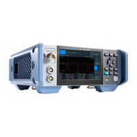
Rohde & Schwarz 1424.9308K02 User Manual (530 pages)
Power Meter
Brand:
Rohde & Schwarz
| Category:
Measuring Instruments
| Size: 9 MB
Table of Contents
Table of Contents
3
Safety and Regulatory Information
11
Safety Instructions
11
Labels on the Product
13
Korea Certification Class B
14
Warning Messages in the Documentation
14
Data Sheets and Brochures
15
Documentation Overview
15
Getting Started Manual
15
Instrument Security Procedures
15
Printed Safety Instructions
15
User Manual
15
Welcome
15
Key Features
16
Release Notes and Open Source Acknowledgment (OSA)
16
Choosing the Operating Site
17
Getting Started
17
Lifting and Carrying
17
Preparing for Use
17
Unpacking and Checking
17
Setting up the Product
18
Connecting to Power
20
Considerations for Test Setup
20
Connecting Power Sensors
21
Connecting to LAN
21
Connecting USB and External Devices
23
Switching on or off
24
Front Panel Tour
25
Instrument Tour
25
Rear Panel Tour
29
Manual Operation
33
Operating Concepts
33
Start Dialog
33
Main Measurement Dialog
34
Status Information
36
Notification Center
37
Selecting the Display Layout
38
Swapping Measurement Panes
40
Editing Parameters
41
Creating and Saving Screenshots
42
Restricting Manual Operation
42
Remote Operation
43
Remote Control
44
Switching to Remote Control (REMOTE)
44
Returning to Manual Operation (LOCAL)
45
Measurement Basics
46
Parallel Measurements
46
Sensor Assignment and Memory
46
Performing a Measurement
48
Limit Violation
49
Settings Conflict
50
Chapter 6 Measurement and Display Configuration
52
Display Format
54
Forward Unit
54
Resolution
54
Unit
54
Auxiliary Values
55
Scale Lower Limit
55
Scaling
55
Forward Scale Lower Limit, Reflection Scale Lower Limit
56
Forward Scale Upper Limit, Reflection Scale Upper Limit
56
Scale Upper Limit
56
Power └ DIV
57
Start Time
57
Time / DIV
57
Trace Length
57
Forward Reference Value, Reflection Reference Value
58
Forward Relative State, Reflection Relative State
58
Power Span
58
Relative Measurements
58
Limit Monitor
59
Lower Limit
59
Lower Limit State
59
Max Hold
59
Max Hold Function
59
Forward Lower Limit State, Reflection Lower Limit State
60
Upper Limit
60
Upper Limit State
60
Controlling the Measurement
62
Triggering
63
Slope
66
Source
66
Trigger Advanced
66
Trigger Level
66
Trigger Mode
66
Trigger Source
66
Specific Trigger
67
Trigger 2 Input Impedance
68
Trigger Sender Port
68
Trigger Sender State
68
Trigger Synchronize Port
68
Trigger Synchronize State
68
Measurement Settings Dialog
69
Measurement Type
69
Channel Calculation Function
70
Primary Sensor Config, Secondary Sensor Config
70
Primary Sensor, Secondary Sensor
70
Auto Set
71
Parameter Set
71
Preserve Window Settings
71
Quick Setup
71
Continuous Average
72
Continuous Average Result Display
72
Recall Parameter Set
72
Continuous Average Settings
73
Burst Average
74
Burst Average Result Display
75
Burst Average Settings
75
Trace
76
Trace Result Display
76
Trace Settings
77
Trace Marker Dialog
78
Pulse Analysis
81
Pulse Analysis Result Display
82
Pulse Analysis Settings
82
Pulse Analysis Dialog
83
Time Gate
90
Time Gate Result Display
91
Time Gate Settings
92
Gate Configuration Dialog
94
Timeslot
95
Timeslot Result Display
96
Timeslot Settings
98
Timeslot Configuration Dialog
99
Statistics
101
Statistics Result Display
101
Statistics Settings
103
Measurement Settings Dialog
104
Scale Configuration Dialog
105
Statistics Timing Dialog
107
Nrt
108
NRT Result Display
108
Forward
109
NRT Settings
109
Absorption Average
110
Average
110
Ccdf
110
Peak Envelope Power (PEP)
110
Absorption Burst
111
Absorption PEP
111
Burst Average
111
Crest Factor (CF)
111
Off
112
Reflection
112
Reflection Coefficient
112
Return Loss
112
Reverse Power
112
Standing Wave Ratio (SWR)
112
Autoscale
113
Display
113
Measurement Main Configuration Dialog
113
Reflection Ratio
113
Trigger
113
Configuration for All Measurement Types
52
Display Settings
52
Chapter 13.8.6, "Standardized Signals", on Page 351 Mode Settings
115
Mode Settings
115
Chapter 7 Sensor Configuration
115
Correction Settings
119
Filter Settings
122
Range Settings
126
NRT Measurement Type
128
NRT Mode Settings
129
NRT Correction Settings
130
NRT Filter Settings
132
Saving and Recalling Settings
134
Zeroing Sensors
136
Connections
138
System Settings
138
Network Settings
139
Remote Settings
142
Interface - VISA Resource Table
143
Settings Tab
143
VISA Resource Tab
143
Customization of *IDN
144
Emulations Tab
144
GPIB Address
144
Language
144
Custom IDN String
145
Custom OPT String
145
Customization of *OPT
145
Input/Output Settings (I/O)
145
Sensor Manager
151
Instrument Info
154
System Info
154
Security Settings
157
Option Settings
162
Help & Copyrights
165
Hardware Configuration
166
Test
167
Global Settings
168
Installing a License Key
170
Option Management
170
Firmware Update
171
Firmware Update Via PC and USB or Ethernet Connection
171
Hardware and Software Requirements
171
Preparing an Update
172
Updating the Application Firmware
173
Firmware Update Via a USB Flash Memory Stick
176
Hardware and Software Requirements
176
Preparing an Update
176
Updating the Application Firmware
177
Common Commands
178
Conventions Used in SCPI Command Descriptions
178
Remote Control Commands
178
Cls
180
Gtl
180
Gtm
180
Gtr
180
Hfc
180
Llo
180
Nren
180
Dev
181
DMC
181
Emc
181
Ese
181
Esr
181
Gcls
182
Gmc
182
Gopc
182
Gwai
182
Idn
182
Ist
182
Lmc
183
Opc
183
Opt
183
Pmc
183
Pre
183
Psc
184
Rcl
184
Rmc
184
Rst
184
Sav
184
Sre
185
Srq
185
Stb
185
Trg
185
Tst
185
Wai
186
Xese
186
Xesr
186
Xpre
186
Xsre
186
Addressing Measurements and Power Sensors
187
Xstb
187
Making Measurements
188
Using Measure
188
Using Configure and READ
189
Configuring One Setting at a Time
190
Using Configure, Initiate and FETCH
190
Structure of Combining Commands
191
Starting and Ending a Measurement
193
Measurement Settings and Results
196
Configuring Display and Results
197
Configuring the Trigger
229
Selecting the Measurement
238
Selecting the Power Sensor
242
Relative Measurements
243
Continuous Average Measurements
245
Burst Average Measurements
260
Trace Measurements
269
Pulse Analysis Measurements
279
Time Gate Measurements
295
Timeslot Measurements
297
Statistics Measurements
309
NRT Measurements
319
Querying Measurement Results
326
Calculation Functions
328
Selecting a Calculation Function
328
Configuring Sensors
330
Setting the Frequency
330
Sensor Modes
331
Sensor Corrections
335
Sensor Filters
340
Sensor Ranges
348
Standardized Signals
351
Frequency Selective Power Sensors
364
NRT Measurement Type
366
Configuring the Test Generator
376
Configuring the Analog Signal Ouput and the Trigger Input/Output
378
Zeroing
387
Running Selftests
389
Managing Setups and Correction Tables
392
Presetting
399
System Information and Configuration
399
Firmware Update
400
Shutdown and Reboot
400
Network Settings
403
Remote Settings
406
Managing Sensors
409
Instrument Information
410
Date and Time Settings
412
Notifications and Errors
415
General Status Register Commands
419
Locking
419
Using the Status Register
419
Reading the Condition Part
420
Controlling the Enable Part
421
Reading the Event Part
421
Controlling the Negative Transition Part
422
Controlling the Positive Transition Part
423
Remote Emulation
423
R&S NRP2 Compatibility
424
Remote Control Basics
464
Remote Control Interfaces and Protocols
464
USB Interface
464
Ethernet Interface
465
GPIB Interface
468
SCPI Command Structure
468
Syntax for Common Commands
469
Syntax for Device-Specific Commands
469
SCPI Parameters
470
Overview of Syntax Elements
473
Structure of a Command Line
473
Responses to Queries
474
Command Sequence and Synchronization
475
Preventing Overlapping Execution
475
Status Reporting System
475
Hierarchy of the Status Registers
476
Structure of a SCPI Status Register
477
Status Byte (STB) and Service Request Enable Register (SRE)
479
Device Status Register
480
IST Flag and Parallel Poll Enable Register (PPE)
480
Questionable Status Register
482
Standard Event Status and Enable Register (ESR, ESE)
486
Operation Status Register
487
Displaying Information
497
Notifications
497
Troubleshooting
497
Interpreting Notifications and Their Number
498
Performing Tests
501
Collecting Information for Technical Support
502
Contacting Customer Support
502
Transporting
503
Cleaning
504
Disposal
504
Maintenance, Storage and Disposal
504
Storage
504
Glossary: List of Abbreviations
505
List of Commands
507
Index
526
Advertisement
Rohde & Schwarz 1424.9308K02 Getting Started (35 pages)
Power Meter
Brand:
Rohde & Schwarz
| Category:
Measuring Instruments
| Size: 0 MB
Table of Contents
Table of Contents
3
Safety and Regulatory Information
5
Safety Instructions
6
Labels on the Product
9
Warning Messages in the Documentation
9
Korea Certification Class B
10
Documentation Overview
11
Getting Started Manual
11
User Manual
11
Instrument Security Procedures
11
Printed Safety Instructions
12
Specifications and Product Brochures
12
Release Notes and Open Source Acknowledgment (OSA)
12
Key Features
13
Preparing for Use
14
Lifting and Carrying
14
Unpacking and Checking
14
Choosing the Operating Site
15
Setting up the Product
15
Placing the Product on a Bench Top
15
Mounting the Product in a Rack
17
Considerations for Test Setup
18
Connecting to Power
18
Connecting Sensors
19
Sensor Connectors a to D
19
Optional Interface for R&S NRT-Z Sensors (R&S NRX-B9)
20
LAN Interface
21
USB 2.0 Host Interfaces
22
Connecting USB and External Devices
22
Switching on or off
22
Instrument Tour
24
Front Panel Tour
24
Sensor Connectors a and B
24
Module Bay
25
Touchscreen
26
Keys
26
On/Standby Key
28
USB Host Interface
28
Rear Panel Tour
29
Sensor Connectors C and D
29
Trig in / out 2 and out 1 / Trig out Connectors
30
Ethernet Interface
30
USB Device Interface
30
AC Supply and Power Switch
30
IEC 625/IEEE 488 Interface
31
Name Plate
31
Contacting Customer Support
33
Index
34
Rohde & Schwarz 1424.9308K02 Getting Started (34 pages)
Power Meter
Brand:
Rohde & Schwarz
| Category:
Measuring Instruments
| Size: 1 MB
Table of Contents
Table of Contents
3
Safety and Regulatory Information
5
Safety Instructions
5
Labels on the Product
8
Warning Messages in the Documentation
8
Korea Certification Class B
9
Documentation Overview
10
Getting Started Manual
10
User Manual
10
Instrument Security Procedures
10
Printed Safety Instructions
10
Data Sheets and Brochures
11
Release Notes and Open Source Acknowledgment (OSA)
11
Key Features
12
Preparing for Use
13
Lifting and Carrying
13
Unpacking and Checking
13
Choosing the Operating Site
14
Setting up the Product
14
Placing the Product on a Bench Top
14
Mounting the Product in a Rack
16
Considerations for Test Setup
16
Connecting to Power
17
Connecting Power Sensors
18
Sensor Connectors a to D
18
Optional Interface for R&S NRT-Z Sensors (R&S NRX-B9)
19
LAN Interface
20
USB 2.0 Host Interfaces
21
Connecting USB and External Devices
21
Switching on or off
21
Instrument Tour
23
Front Panel Tour
23
Sensor Connectors a and B
23
Module Bay
24
Touchscreen
25
Keys
25
USB Host Interface
27
On/Standby Key
27
Rear Panel Tour
28
Trig in / out 2 and out 1 / Trig out Connectors
28
Ethernet Interface
29
USB Device Interface
29
USB Host Interface
29
AC Supply and Power Switch
29
IEC 625/IEEE 488 Interface
30
Name Plate
30
Sensor Connectors C and D
31
Contacting Customer Support
32
Index
33
Advertisement
Advertisement
Related Products
Rohde & Schwarz 1424.9208.02
Rohde & Schwarz 1424.9308.02
Rohde & Schwarz 1424.9208K02
Rohde & Schwarz 1424.7805.02
Rohde & Schwarz 1424.8901.02
Rohde & Schwarz 1424.8601.02
Rohde & Schwarz 1424.7805K02
Rohde & Schwarz 1424.8901K02
Rohde & Schwarz 1424.8301K02
Rohde & Schwarz 1424.8601K02
Rohde & Schwarz Categories
Measuring Instruments
Test Equipment
Portable Generator
Power Supply
Accessories
More Rohde & Schwarz Manuals
Login
Sign In
OR
Sign in with Facebook
Sign in with Google
Upload manual
Upload from disk
Upload from URL