
Related Manuals for Parker Coral Sea


Summary of Contents for Parker Coral Sea
- Page 1 Coral Sea Owner’s Manual Parker Hannifin 2630 E. El Presidio Street Carson, CA 90810 www.parker.com/watermakers...
-
Page 2: Table Of Contents
TABLE OF CONTENTS SYSTEM DESCRIPTION PRE-INSTALLATION NOTES ELECTRICAL INFORMATION INSTALLATION REQUIREMENTS OPERATIONS MANUAL R.O. MEMBRANE INSTALL & CARE MAINTENANCE AND REPAIR COMPONENT USER MANUALS DRAWING PULL-OUTS SPARE PARTS LIST Coral Sea Owner's Manual... -
Page 3: System Description
SECTION 1 SYSTEM DESCRIPTION Coral Sea Owner's Manual... - Page 4 C & 35,000 PPM TDS typical seawater 57.7 Kg/cm2 ◦ C & 35,000 PPM TDS typical seawater Model Number Gallons/Day Liters/Day 2800 2800 10,599 3600 3600 13,627 4200 4200 15,899 5200 5200 19,684 6200 6200 23,470 6800 6800 25,741 Coral Sea Owner's Manual...
- Page 5 TYPE: Selected aromatic tri-polyamid, thin film composite, spiral wound, single pass reverse osmosis membrane element. CHLORINE TOLERANCE: 0.1 PPM SYSTEM PRESSURE: Minimum: 15 psi Maximum: 60 psi 1 bar 4.1 bar 103 kPa 414 kPa 1 Kg/cm2 4.2 Kg/cm2 Coral Sea Owner's Manual...
- Page 6 Standard) Standard) Standard) Standard) Standard) Product ½ Inch ½ Inch ¾ Inch ¾ Inch ¾ Inch ¾ Inch Flange Flange Flange Flange Flange Flange (American (American (American (American (American (American Standard) Standard Standard) Standard) Standard) Standard) Coral Sea Owner's Manual...
- Page 7 Hannifin system from a source that creates a 60 Hz if you have a 50 Hz System. If the Parker Hannifin system is set up for 50 Hz and operated at 60 Hz, the motor will turn too fast and require excessive power. This over stresses and overheats the motor. If the Parker Hannifin system is set up for 60 Hz but operated at 50 Hz, R.O.
- Page 8 IMMEDIATE MEDICAL ATTENTION. THOROUGHLY WASH AFFECTED SKIN AFTER HANDLING PRODUCT. CONTACT A PHYSICIAN IF IRRITATION PERSISTS. MEDICAL PERSONNEL FAMILIAR WITH: Parker Hannifin’s “SRC MCC1”, R.O. MEMBRANE ELEMENT ALKALINE DETERGENT CLEANING CHEMICAL are available 24 HOURS A DAY, 7 DAYS A WEEK, U.S.A. TOLL FREE MEDICAL EMERGENCY NUMBER 1-800-228-5635.
- Page 9 ATTENTION. THOROUGHLY WASH AFFECTED SKIN AFTER HANDLING PRODUCT. CONTACT A PHYSICIAN IF IRRITATION PERSISTS. MEDICAL PERSONNEL FAMILIAR WITH: Parker Hannifin’s “SRC MCC3”, R.O. MEMBRANE ELEMENT RUST REMOVER CLEANING CHEMICAL are available 24 HOURS A DAY, 7 DAYS A WEEK, U.S.A. TOLL FREE MEDICAL EMERGENCY NUMBER 1-800-228-5635.
- Page 10 (12) months and specifi cally listed components are warranted for up to 5 years from the date of shipment. Parker Hannifi n, under no circumstances, is liable for damages arising out of or in any way connected with the failure of the system to perform as set forth herein.
- Page 11 Coral Sea Vertical 6800 Some of the damages that may not be covered by the warranty include: a) Use of non-authorized or misuse of authorized chemicals for storage will void any warranty. b) Rust fouling of the R.O. Membrane Element is not covered under warranty.
- Page 12 Coral Sea Vertical 6800 TEMPERATURE & PRESSURE EFFECTS Parker Hannifi n® TEMPERATURE EFFECT COMPARISON CHART (At 820 psi & 35,000 ppm feedwater TDS conditions) The Temperature Effect Chart on this page illustrates the loss or gain of productivity across the R.O. Membrane.
- Page 13 (Do not use this chart for brackish water systems & applications) As the seawater temperature increases, the Parker Hannifi n system pressure must be adjusted so that the system achieves no greater than 100% of rated product water fl ow. Product water fl ow greater than 100% of rated capacity causes premature fouling of the R.O.
-
Page 14: Pre-Installation Notes
SECTION 2 PRE-INSTALLATION NOTES Coral Sea Owner's Manual... - Page 15 Coral Sea Vertical 6800 PRE-INSTALLATION NOTES PRECAUTIONS connect the inlet of the System to the ship’s potable water system if the ships system contains chlorinated or STORAGE PRIOR TO UNCRATING brominated water. These chemicals destroy the copolymer Adhere to crate markings: components within the RO system.
- Page 16 Coral Sea Vertical 6800 c. An electrical power source capable of supplying the during system operation. proper current at the proper AC Voltage, Cycles and e. Potable Water Storage Tank [62] with Product Water Phase to the System. Storage Tank Connection and product water line with d.
- Page 17 Coral Sea Vertical 6800 electrically grounded to a proper electrical grounding Locate the System in a well-ventilated area. source. 2.2 PIPING AND INTERCONNECT LENGTH OF CONNECTION LINES: DIAGRAMS The System operates most effi ciently with interconnect The P&ID illustration foldout in Section 10.
- Page 18 Coral Sea Vertical 6800 DAMAGE TO THE SYSTEM CAUSED natural fi lter bed. BY THE OPERATION OF THE SYSTEM B. SUCTION LINE SUBSYSTEM: WITHOUT R.O. MEMBRANE ELEMENTS This section of the System fi lters suspended solids INSTALLED IS: NOT COVERED BY THE SEA from the feedwater of the system before it reaches the RECOVERY WARRANTY;...
- Page 19 Coral Sea Vertical 6800 costs. Sea Recovery utilizes a high effi ciency, marine Media Filter backwash fl ow control meter measures quality pump which delivers approximately 40 psi (2.8 the rate of the backwash water progress through bar) into the Media Filter.
- Page 20 Coral Sea Vertical 6800 the Media Filter and inlet of the primary 20 micron Proper interpretation of the GPM water fl ow meter cartridge pre-fi lter allow for observation of the readings, and movements, will allow the user condition of the Media Filter when correlated to to determine the need for maintenance or the pressure gauge.
- Page 21 Coral Sea Vertical 6800 High pressure pump (optional): This is a marine water. The remainder, becomes a concentrated brine quality positive displacement ceramic plunger pump solution which carries rejected salt ions away from with stainless steel manifold. the membrane element and back to the feed water source.
- Page 22 Coral Sea Vertical 6800 shutdown the System. from the product water storage tank or cistern. Brine discharge line atmospheric check valve allows Temperature compensated salinity probe is directly for natural drainage of the discharge line without connected to the salinity controller, and sends a creating a vacuum in the line.
- Page 23 Coral Sea Vertical 6800 SRC System. R.O. membrane vessel assemblies. 13. Product water ultraviolet sterilizer destroys at Cleaning system fl ow restricter limits the fl ow or least 99.9% of any virus, bacteria and other velocity of the cleaning chemical to an effective fl ow microorganisms which may pass through the SRC rate.
- Page 24 Coral Sea Vertical 6800 Salinity Controller is the central point of connection 13. Flow meter - FL 1003 4-40 gpm (15.1-151 lpm) for all electrical lines in the System. The controller measures the combined rate of the backwash water monitors the salt content of the product water (by through the Media Filters.
-
Page 25: Electrical Information
SECTION 3 ELECTRICAL INFORMATION Coral Sea Owner's Manual... - Page 26 Coral Sea Horizontal 6800 ELECTRICAL INFORMATION ELECTRICAL REQUIREMENTS & INFORMATION High Pressure Pump Electric Motor starting amperage. Normal operational amperage equals the normal operating Following are general electrical requirements and amperage of the Booster Pump Electric Motor plus the information for Coral Sea.
- Page 27 Coral Sea Horizontal 5800 3.2 RECOMMENDED CIRCUIT BREAKER SIZE The recommended Circuit Breaker Size assumes that the R.O. System is equipped with up to three electric motors (Well Pump Motor, Booster Pump Motor, and High Pressure Pump Motor). If an optional Feed Pump is not used, the Circuit Breaker maybe resized appropriately to handle only two motors.
-
Page 28: Installation Requirements
SECTION 4 INSTALLATION REQUIREMENTS Coral Sea Owner's Manual... - Page 29 Parker There should be no valving in this line. Damage to the Hannifi n warranty. Grind fl at or use appropriate shims on...
- Page 30 Coral Sea Vertical 6800 per system specifi cation and wiring diagram in Section instructions. Install all other component wiring per system specifi cation CAUTION: The Membrane and Vessel and wiring diagram. assembly is packaged with storage solution. Avoid skin and eye contact with this solution.
- Page 31 Coral Sea Vertical 6800 TABLE 4-1 TABEL 4-2 Refer to the P&ID illustration at back of this manual. Refer to the P&ID illustration at the back of this manual. Use the recommended hose or piping as required to Use the recommended tube to interconnect the System...
- Page 32 Coral Sea Vertical 6800 4.5 LAND FEED WATER PICK-UP LAND INSTALLATION FEED WATER PICK-UP INFORMATION Refer to the following illustrations. Example of Feed Water Intake from a Deep Well for a Land Installation Shut Off Valve for maintenance of Check Valve Non Return to keep Strainer and Feed Water Pump prime in place.
- Page 33 Coral Sea Vertical 6800 Example of Water intake from a Feed Source 4.6 UV STERILIZER INSTALLATION If applicable, the UV Sterilizer is normally installed when the System is shipped; otherwise, install the UV Sterilizer Assembly per System P&ID and Wiring diagram.
- Page 34 Coral Sea Vertical 6800 This page is intentionally left blank. Coral Sea Owner's Manual Page 4-6...
-
Page 35: Operations Manual
SECTION 5 OPERATIONS MANUAL Coral Sea Owner's Manual... - Page 36 THIS PAGE INTENTIONALLY LEFT BLANK Coral Sea Owner's Manual...
- Page 37 Coral Sea Control System Operations Manual (Base System) PLC Firmware Version: 4.01 HMI Firmware Version: 4.01 Project: Doc: Version: Parker Sea Recovery Coral Sea 1010016 Document Name: Author: Page: Control System Operations Manual Page 1 of 129 Coral Sea Owner's Manual...
- Page 38 Internet. Modbus is governed by the Modbus-IDA Organization, a merger of the Modbus Organization and IDA Group in 2003. For more information, visit www.modbus.org. Project: Doc: Version: Parker Sea Recovery Coral Sea 1010016 Document Name: Author: Page: Control System Operations Manual...
- Page 39 5. Normal Operation ………………………………………………………………………………………. Overview ……………………………………………………………………………… Starting the System Manually ………………………………………………. Auxiliary Feed Pump Activation (if installed) ……………………….. Project: Doc: Version: Parker Sea Recovery Coral Sea 1010016 Document Name: Author: Page: Control System Operations Manual Page 3 of 129 Coral Sea Owner's Manual...
- Page 40 15. Emergency Operation …………………………………………………………………………………… 100 15.1 Accessing Emergency Override Menus …………………………………… 15.2 Accessing Emergency Override Operation Time …………………….. Project: Doc: Version: Parker Sea Recovery Coral Sea 1010016 Document Name: Author: Page: Control System Operations Manual Page 4 of 129 Coral Sea Owner's Manual...
- Page 41 19.13 The automatic multi-media backwashing sequence ………………. 19.14 Aborting automatic backwashing cycles ………………………………… 19.15 Automatic multi-media faults ………………………………………………… 128 Project: Doc: Version: Parker Sea Recovery Coral Sea 1010016 Document Name: Author: Page: Control System Operations Manual Page 5 of 129...
-
Page 42: Settings Prior To Attempting Operation
Not relevant MV-1005 Media filter rinse valve Normal position (Tab Down) CV-1002 Media System Check Valve Not relevant Continuation of Coral Sea Standard System Equipment: CV-1000 Feed System check Valve Not relevant FIL-1000 20u Cartridge filter assembly Not relevant PI-1003... - Page 43 Fresh water flush carbon filter Not relevant MV-1006 Fresh water flush control valve Fully Closed Project: Doc: Version: Parker Sea Recovery Coral Sea 1010016 Document Name: Author: Page: Control System Operations Manual Page 7 of 129 Coral Sea Owner's Manual...
-
Page 44: The Control Panel
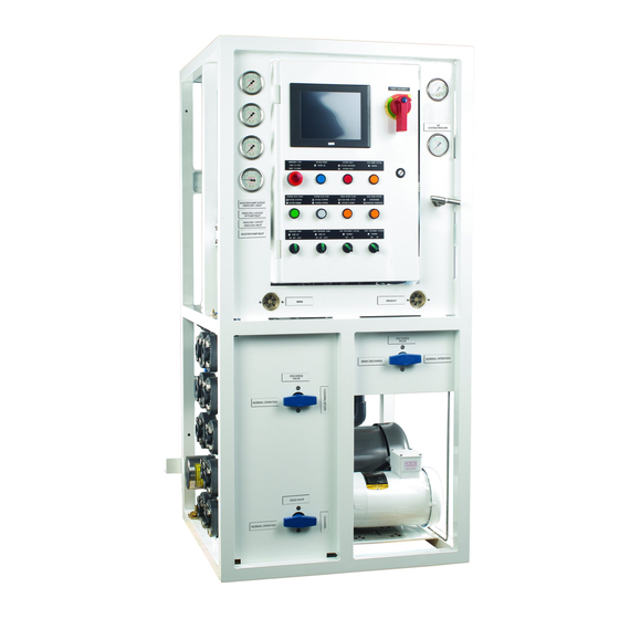
Fresh Water Flush Indicator System Fault Indicator Main Power Disconnect Media Filter Backwash Button/Indicator Media Filter Rinse Indicator Project: Doc: Version: Parker Sea Recovery Coral Sea 1010016 Document Name: Author: Page: Control System Operations Manual Page 8 of 129 Coral Sea Owner's Manual... - Page 45 Coral Sea water maker. Via the Modbus interface it is possible to monitor all control system inputs and outputs; it is also possible to monitor data normally displayed on the control system touch screen including alarm information, performance information, system pressure information and salinity information.
-
Page 46: Initial System Checks/Commissioning
May, 2015 Initial System Checks/Commissioning. The new Coral Sea control system comes loaded with a special utility tool designed to aid in the initial system checks and commissioning of the system. This utility can be accessed in the following manner. - Page 47 (healthy). Press Here Project: Doc: Version: Parker Sea Recovery Coral Sea 1010016 Document Name: Author: Page: Control System Operations Manual...
- Page 48 Press Here Project: Doc: Version: Parker Sea Recovery Coral Sea 1010016 Document Name: Author: Page: Control System Operations Manual...
- Page 49 ‘Off’ position. Press Here Press Here Press Here Press Here Press Here Project: Doc: Version: Parker Sea Recovery Coral Sea 1010016 Document Name: Author: Page: Control System Operations Manual Page 13 of 129 Coral Sea Owner's Manual...
-
Page 50: Motor And Pump Rotation Checks
Always ensure incoming power to the unit has been disconnected and locked off before proceeding with altering outgoing power connections. Failure to do so could result in injury or death. Project: Doc: Version: Parker Sea Recovery Coral Sea 1010016 Document Name: Author: Page: Control System Operations Manual... - Page 51 This will return you to the main operations menu. Project: Doc: Version: Parker Sea Recovery Coral Sea 1010016 Document Name: Author: Page: Control System Operations Manual...
-
Page 52: Valve Operation Checks
Fault Notice Press the ‘Fault Log’ button to be taken to the fault message center screen as detailed on the next page Project: Doc: Version: Parker Sea Recovery Coral Sea 1010016 Document Name: Author: Page: Control System Operations Manual... - Page 53 Pressing ‘Back’ will exit the alarm list. Please note the ‘Back’ button is only active if no faults or errors are currently displayed, if errors or faults are displayed, press ‘Accept’ to exit this screen. Project: Doc: Version: Parker Sea Recovery Coral Sea 1010016 Document Name: Author: Page:...
- Page 54 Analog CH4 (PT-1001). Illuminates if the input is enabled and the connected sensor is healthy CH7: Analog CH5 (PT-1002). Illuminates if the input is enabled and the connected sensor is healthy Project: Doc: Version: Parker Sea Recovery Coral Sea 1010016 Document Name: Author: Page: Control System Operations Manual...
-
Page 55: Editing System Set-Points
Parker Sea Recovery Engineering group. Hence access to the system set-point editing mode has been restricted with a password. To gain access to these features, please contact Parker Sea Recovery to obtain the required password. - Page 56 May, 2015 Once this area has been pressed the password entry dialogue box will appear. Enter the password given to you by Parker Sea Recovery, and press the ‘ENT’ key. To cancel this operation press the ‘CAN’ key as shown below:...
-
Page 57: Minimum Fwf Pressure
7 days before repeating the flushing cycle. Typical values entered here are 600 Seconds in all applications Project: Doc: Version: Parker Sea Recovery Coral Sea 1010016 Document Name: Author: Page:... -
Page 58: Minimum Hp Pump Inlet Pressure
CAT pump this value can be reduced Typical values entered here are 350 PSI in Danfoss pump applications Typical values entered here are 100 PSI in CAT pump applications Project: Doc: Version: Parker Sea Recovery Coral Sea 1010016 Document Name: Author: Page: Control System Operations Manual... -
Page 59: System Maximum Operating Pressure
Operation over these hours is allowed, but is not recommended. Typical values entered here are 8000 Hrs in Danfoss pump applications Typical values entered here are 2000 Hrs in CAT pump applications Project: Doc: Version: Parker Sea Recovery Coral Sea 1010016 Document Name: Author: Page: Control System Operations Manual... -
Page 60: Low Pressure Valve Actuation Time
Enter the newly required set-point and press the ‘ENT’ button to complete entry, to cancel the request press the ‘CAN’ button as illustrated on the next page: Project: Doc: Version: Parker Sea Recovery Coral Sea 1010016 Document Name: Author: Page:... -
Page 61: System Minimum Brine Flow Rate
Typical values entered here are 10 GPM for 2600 and 3600 systems Typical values entered here are 18 GPM for 4200 systems and above Project: Doc: Version: Parker Sea Recovery Coral Sea 1010016 Document Name: Author: Page: Control System Operations Manual... -
Page 62: Domestic Max. Salinity Level
This will allow you to change the time and date stored within the touch screen. To access this high level editing screen a password is required. Contact Parker Sea Recovery for further details To exit the system settings screens you must press the “Save Settings’ button located in the lower right hand corner of the second settings screen, even if you have not applied any changes to the system settings, this button must be pressed to exit the settings screen. - Page 63 Pressing on the area shown will prompt the controller to ask you for the super user access password via the illustrated dialogue box. This password must be obtained from Parker Sea Recovery. Enter the password given to you by Parker Sea Recovery, and press the ‘ENT’ key. To cancel this operation press the ‘CAN’ key as shown below:...
- Page 64 Enter desired set- point value here To cancel press here Enter Value and press here Project: Doc: Version: Parker Sea Recovery Coral Sea 1010016 Document Name: Author: Page: Control System Operations Manual Page 28 of 129 Coral Sea Owner's Manual...
-
Page 65: System Size Selector
Pressing this button causes the control system scroll through the available system recovery sizes within Coral Sea product line, each time the button is pressed the system will increment to the next available size as listed here: 2800, 3600, 4200, 5200, 6200 & 6800. Once the maximum system size has been reached pressing the system size selection button again will cause the system to return the beginning of the list. -
Page 66: Max Product
To save your changes navigate to the second or third set-point editing screen and press the ‘Save Setting’ button as illustrated on the next page: Project: Doc: Version: Parker Sea Recovery Coral Sea 1010016 Document Name: Author: Page:... - Page 67 Once the saving procedure has been completed, the controller will return to the main splash screen as illustrated on the next page: Project: Doc: Version: Parker Sea Recovery Coral Sea 1010016 Document Name: Author: Page:...
- Page 68 May, 2015 Once the system has returned to the main splash screen, set-point data saving is complete and set point editing mode is canceled. Project: Doc: Version: Parker Sea Recovery Coral Sea 1010016 Document Name: Author: Page: Control System Operations Manual...
-
Page 69: Normal Operation
Normal Operation Overview The new Coral Sea control system has two possible methods of operation; these are manual mode and automatic mode. In manual mode the controller requires that the operator activate the pumps by turning the relative pump operator switches to the ‘Pump On’ position. If the user attempts to operate a... -
Page 70: Auxiliary Feed Pump Activation (If Installed)
Pressing ‘Ignore’ clears the performance warning; pressing ‘Show Log’ will open the performance warning log window where details concerning the detected problem are given as shown below: Project: Doc: Version: Parker Sea Recovery Coral Sea 1010016 Document Name: Author: Page:... -
Page 71: High Pressure Pump Activation
Pressing ‘Ignore’ clears the performance warning; pressing ‘Show Log’ will open the performance warning log window where details concerning the detected problem are given as shown on the next page: Project: Doc: Version: Parker Sea Recovery Coral Sea 1010016 Document Name: Author: Page: Control System Operations Manual... -
Page 72: Auxiliary Product Pump Activation (If Installed)
(Manual Salinity Control Operation), if the sensor reports a healthy state the control system will begin to monitor membrane pressures. If the system detects pressure are below the Project: Doc: Version: Parker Sea Recovery Coral Sea 1010016 Document Name: Author: Page:... - Page 73 The operator must manually increase system pressure by turning the ‘System Pressure Regulator’ in a clockwise direction. If the operator fails to increase system pressure Project: Doc: Version: Parker Sea Recovery Coral Sea 1010016 Document Name: Author: Page:...
- Page 74 Pressing ‘Move Up’ will scroll up through the alarm list Pressing ‘Move Down’ will scroll down through the alarm list Pressing ‘Accept’ will clear the listed alarm notifications. Project: Doc: Version: Parker Sea Recovery Coral Sea 1010016 Document Name: Author: Page: Control System Operations Manual...
- Page 75 Pressing ‘Select’ will highlight the first alarm item. Pressing ‘Move Up’ will scroll up through the alarm list Pressing ‘Move Down’ will scroll down through the alarm list Project: Doc: Version: Parker Sea Recovery Coral Sea 1010016 Document Name: Author: Page: Control System Operations Manual...
- Page 76 ‘Accept’ to exit this screen. The operator must now manually close the product diversion valve as soon as possible to prevent contamination of the potable water supply. Project: Doc: Version: Parker Sea Recovery Coral Sea 1010016 Document Name: Author: Page: Control System Operations Manual...
-
Page 77: Manual Salinity Control Operation
If the valve fails to activate properly the control system will raise a performance warning message detailing the problem as shown on the next page: Project: Doc: Version: Parker Sea Recovery Coral Sea 1010016 Document Name: Author: Page: Control System Operations Manual... - Page 78 If high salinity levels are measured again press the diversion valve control button to close the valve. Once this Project: Doc: Version: Parker Sea Recovery Coral Sea 1010016 Document Name: Author: Page:...
- Page 79 The operator must manually actuate the product diversion valve as soon as possible to prevent contamination of the potable water supply. (See Manual Actuation of System Valves). Project: Doc: Version: Parker Sea Recovery Coral Sea 1010016 Document Name: Author: Page:...
-
Page 80: Manual Shutdown
Pressing ‘Ignore’ clears the performance warning; pressing ‘Show Log’ will open the performance warning log window where details concerning the detected problem are given as shown on the next page: Project: Doc: Version: Parker Sea Recovery Coral Sea 1010016 Document Name: Author: Page: Control System Operations Manual... - Page 81 (if fitted). When the system is shut down manually in this manner fresh water flushing will not take place. Project: Doc: Version: Parker Sea Recovery Coral Sea 1010016 Document Name: Author: Page:...
-
Page 82: Automatic Start-Up Operation
May, 2015 Automatic Start up Operation Automatic start up operation is a new feature added to the Coral Sea Series of products. It allows for virtually hands free start up of the system and all associated equipment. This automatic start up operation can also be carried out remotely via the Modbus communications link (if installed). - Page 83 If no pre-check errors are detected the control system will begin a 10 second count-down. During the count-down the system will beep intermittently and display a warning screen as shown on the next page: Project: Doc: Version: Parker Sea Recovery Coral Sea 1010016 Document Name: Author: Page: Control System Operations Manual...
- Page 84 Pressing ‘Show Log’ will open the system fault log window where details concerning the detected fault are given as shown on the next page: Project: Doc: Version: Parker Sea Recovery Coral Sea 1010016 Document Name: Author: Page: Control System Operations Manual...
- Page 85 All running pumps are shutdown and the controller will display a system fault notification screen detailing the problem (See System Critical Error Messages), as shown below: Press here to review fault Project: Doc: Version: Parker Sea Recovery Coral Sea 1010016 Document Name: Author: Page: Control System Operations Manual Page 49 of 129...
- Page 86 Press here Press here to to ignore review error Project: Doc: Version: Parker Sea Recovery Coral Sea 1010016 Document Name: Author: Page: Control System Operations Manual Page 50 of 129 Coral Sea Owner's Manual...
- Page 87 (See System Critical Error Messages), as shown below: Press here to review fault Project: Doc: Version: Parker Sea Recovery Coral Sea 1010016 Document Name: Author: Page: Control System Operations Manual Page 51 of 129...
- Page 88 (See System Critical Error Messages), as shown on the next page: Project: Doc: Version: Parker Sea Recovery Coral Sea 1010016 Document Name: Author: Page:...
- Page 89 ‘Clear’ to exit this screen. The operator must correct the detected problem before re-attempting automatic operation. Project: Doc: Version: Parker Sea Recovery Coral Sea 1010016 Document Name: Author: Page: Control System Operations Manual...
- Page 90 Pressing ‘Back’ will exit the alarm list. Please note the ‘Back’ button is only active if no faults or errors are currently displayed, if errors or faults are displayed, press ‘Accept’ to exit this screen. Project: Doc: Version: Parker Sea Recovery Coral Sea 1010016 Document Name: Author: Page:...
- Page 91 Pressing ‘Show Log’ will open the system fault log window where details concerning the detected fault are given as shown below: Project: Doc: Version: Parker Sea Recovery Coral Sea 1010016 Document Name: Author: Page: Control System Operations Manual...
- Page 92 Pressing ‘Ignore’ clears the performance warning; pressing ‘Show Log’ will open the performance warning log window where details concerning the detected problem are given as shown below: Project: Doc: Version: Parker Sea Recovery Coral Sea 1010016 Document Name: Author: Page:...
- Page 93 Pressing ‘Ignore’ clears the performance warning; pressing ‘Show Log’ will open the performance warning log window where details concerning the detected problem are given as shown on the next page: Project: Doc: Version: Parker Sea Recovery Coral Sea 1010016 Document Name: Author: Page: Control System Operations Manual...
- Page 94 ‘Accept’ to exit this screen. The system will continue to operate in this state continuously or until shutdown by the operator, or a fault is detected. Project: Doc: Version: Parker Sea Recovery Coral Sea 1010016 Document Name: Author: Page: Control System Operations Manual...
-
Page 95: Automatic Shutdown Operation
Pressing ‘Show Log’ will open the system fault log window where details concerning the detected fault are given as shown below: Project: Doc: Version: Parker Sea Recovery Coral Sea 1010016 Document Name: Author: Page: Control System Operations Manual... - Page 96 ‘Clear’ to exit this screen. The operator must correct the detected problem before re-attempting automatic operation. Project: Doc: Version: Parker Sea Recovery Coral Sea 1010016 Document Name: Author: Page: Control System Operations Manual...
-
Page 97: Emergency Shutdown Operation
Pressing ‘Show Log’ will open the system fault log window where details concerning the detected fault are given as shown below: Project: Doc: Version: Parker Sea Recovery Coral Sea 1010016 Document Name: Author: Page: Control System Operations Manual... - Page 98 ‘Clear’ to exit this screen. The operator must release the E-Stop button and accept this warning before re-attempting automatic operation. Project: Doc: Version: Parker Sea Recovery Coral Sea 1010016 Document Name: Author: Page: Control System Operations Manual...
-
Page 99: System Critical Error Messages
May, 2015 System Critical Error Messages The Coral Sea control system contains three message centers, all of which are intended to provide as much information to the operator as possible. The main of the three message centers is the critical error message center. - Page 100 ‘Auto-Stop’ button for 2 seconds. Project: Doc: Version: Parker Sea Recovery Coral Sea 1010016 Document Name: Author: Page:...
-
Page 101: System Fault Codes And Possible Causes
Check the system messaging area for help diagnosing Start-Up Aborted the type of failure detected, and rectify before continuing Project: Doc: Version: Parker Sea Recovery Coral Sea 1010016 Document Name: Author: Page: Control System Operations Manual Page 65 of 129... - Page 102 Check the system messaging area for help diagnosing Start-Up Aborted ** the type of failure detected, and rectify before continuing Project: Doc: Version: Parker Sea Recovery Coral Sea 1010016 Document Name: Author: Page: Control System Operations Manual Page 66 of 129...
- Page 103 Start-Up Aborted required values. Check the system filtration chain for clogged filters, backwash the sand filter if required Project: Doc: Version: Parker Sea Recovery Coral Sea 1010016 Document Name: Author: Page: Control System Operations Manual Page 67 of 129...
- Page 104 Valve Position Inappropriate** media outlet valve was detected, the failure in position feedback has triggered a shutdown. Project: Doc: Version: Parker Sea Recovery Coral Sea 1010016 Document Name: Author: Page: Control System Operations Manual Page 68 of 129...
- Page 105 Pressure Switch Fault switch. Run the system at pressures below maximum (975 PSI) Project: Doc: Version: Parker Sea Recovery Coral Sea 1010016 Document Name: Author: Page: Control System Operations Manual Page 69 of 129...
- Page 106 Domestic Diversion Valve Closing failure to respond to close command fault, or a close Fault command motion failed to complete. Project: Doc: Version: Parker Sea Recovery Coral Sea 1010016 Document Name: Author: Page: Control System Operations Manual Page 70 of 129...
- Page 107 Media Filter Inlet Valve Closing failure to respond to close command fault, or a close Fault** command motion failed to complete. Project: Doc: Version: Parker Sea Recovery Coral Sea 1010016 Document Name: Author: Page: Control System Operations Manual Page 71 of 129...
- Page 108 Media Filter Outlet Valve Closing failure to respond to close command fault, or a close Fault** command motion failed to complete. Project: Doc: Version: Parker Sea Recovery Coral Sea 1010016 Document Name: Author: Page: Control System Operations Manual Page 72 of 129...
- Page 109 Media Filter Rinse Valve Closing failure to respond to close command fault, or a close Fault** command motion failed to complete. Project: Doc: Version: Parker Sea Recovery Coral Sea 1010016 Document Name: Author: Page: Control System Operations Manual Page 73 of 129...
- Page 110 Check 5 x 20 mm fuses within control panel for failures (indicated by red light) ** = Indicates optional components Project: Doc: Version: Parker Sea Recovery Coral Sea 1010016 Document Name: Author: Page: Control System Operations Manual Page 74 of 129...
-
Page 111: System Performance Messages
May, 2015 System Performance Messages The Coral Sea control system contains three message centers, all of which are intended to provide as much information to the operator as possible. The most commonly displayed of the three message centers is the performance message center. - Page 112 This list of potential problems can be viewed at any time by manually navigating back to the performance message center (See Menu Navigation) Project: Doc: Version: Parker Sea Recovery Coral Sea 1010016 Document Name: Author: Page: Control System Operations Manual...
-
Page 113: System Performance Notification And Possible Causes
Stop system has been activated. Check all E-Stop E-Stop Button Activated buttons and release any currently pressed in by turning in a clockwise direction Project: Doc: Version: Parker Sea Recovery Coral Sea 1010016 Document Name: Author: Page: Control System Operations Manual Page 77 of 129... - Page 114 Sensor PT-1002 In By-pass screen and activated the emergency by-pass of the PT- Mode** 1002 pressure sensor. Project: Doc: Version: Parker Sea Recovery Coral Sea 1010016 Document Name: Author: Page: Control System Operations Manual Page 78 of 129 Coral Sea Owner's Manual...
- Page 115 Not Currently Producing Potable been able to product potable water within the normal Water (Extended) time frames. Check system pressure settings Project: Doc: Version: Parker Sea Recovery Coral Sea 1010016 Document Name: Author: Page: Control System Operations Manual Page 79 of 129...
- Page 116 Operation Not Possible Max. mode for the maximum allowable time. The damaged Emergency Hours Reached sensor must be replaced to continue. Project: Doc: Version: Parker Sea Recovery Coral Sea 1010016 Document Name: Author: Page: Control System Operations Manual Page 80 of 129...
- Page 117 70% of normal; this could indicate massive High Possible HP Pump Wear Pressure pump wear. ** = Indicates optional components Project: Doc: Version: Parker Sea Recovery Coral Sea 1010016 Document Name: Author: Page: Control System Operations Manual Page 81 of 129...
-
Page 118: System Status Messages
May, 2015 System Status Messages The Coral Sea control system contains three message centers, all of which are intended to provide as much information to the operator as possible. The most commonly used of the three message centers is usually the system status message center. -
Page 119: Menu Navigation
May, 2015 Menu Navigation The new Coral Sea control system has many user interface menus and screens, all of which are designed to present as much information to the operator as possible. Navigating these screens is quite simple and begins when moving from the home screen by pressing the arrow in the lower right corner of the screen. -
Page 120: Accessing The 'System Operation' Screen
Accessing the salinity monitor requires one further step. Press on the arrow next to the’ System Salinity’ text as detailed on the next page: Project: Doc: Version: Parker Sea Recovery Coral Sea 1010016 Document Name: Author: Page:... - Page 121 As you press the ‘PPM’ button the type of display you see will differ depending on what the regional settings are within the water maker (US/EU) as shown on the next page: Project: Doc: Version: Parker Sea Recovery Coral Sea 1010016 Document Name: Author: Page:...
-
Page 122: Accessing System Pressure And Flow Screens
‘System Pressures & Flows’ text. Pressing this arrow will take you to the pressure monitoring screen as shown on the next page: Project: Doc: Version: Parker Sea Recovery Coral Sea 1010016 Document Name: Author: Page:... - Page 123 When switching between PSI/GPM and Bar/m3 the system will remember the last chosen unit of display and will automatically return to it when you next access the system pressures and flows display feature. Project: Doc: Version: Parker Sea Recovery Coral Sea 1010016 Document Name: Author: Page:...
-
Page 124: Accessing Automatic Multi-Media System Pressure Screens
By default the system will display system pressures in PSI. This can be changed to Bar if the user prefers this measuring system. To change from PSI to Bar press the ‘MET’ button in the upper right section of Project: Doc: Version: Parker Sea Recovery Coral Sea 1010016 Document Name: Author: Page:... -
Page 125: Accessing System Message Centers
Pressing this button will lead you to the ‘System Message Selection’ Screen, from here you can access all three of the control system message centers. Project: Doc: Version: Parker Sea Recovery Coral Sea 1010016 Document Name: Author: Page: Control System Operations Manual... - Page 126 Performance Messages’, doing so will open the requested message center as shown below: Press here to go back To return back to the menu screen press the back button Project: Doc: Version: Parker Sea Recovery Coral Sea 1010016 Document Name: Author: Page: Control System Operations Manual Page 90 of 129...
- Page 127 To return to the main menu screen press the arrow in the top left corner of the screen, pressing this button will return you to the main menu screen as shown below: Project: Doc: Version: Parker Sea Recovery Coral Sea 1010016 Document Name: Author: Page:...
-
Page 128: Accessing High Pressure Pump Hour Meter
Danfoss Pumps/2000hrs for CAT Pumps or over, until this time, the ‘Reset’ button is not active. Pressing the arrow in the top left hand corner of the screen will return you to the ‘System Menu’ screen. Project: Doc: Version: Parker Sea Recovery Coral Sea 1010016 Document Name: Author: Page:... -
Page 129: Accessing Filed Sensor Zero Point Calibration Screen
From this screen you can perform a zero-pressure calibration of the pressure sensor system. Please see the ‘System Maintenance’ section for further details. Project: Doc: Version: Parker Sea Recovery Coral Sea 1010016 Document Name: Author: Page: Control System Operations Manual... -
Page 130: Accessing Salinity Sensor Calibration Screen
Press the ‘CAN’ key to cancel this request. Entering the correct password will bring you to the following screen. Press Here To Go Back Project: Doc: Version: Parker Sea Recovery Coral Sea 1010016 Document Name: Author: Page: Control System Operations Manual Page 94 of 129... - Page 131 Pressing the arrow in the top left had corner of the ‘Salinity Sensor Calibration’ screen will return you to the ‘System Menu’ screen. Project: Doc: Version: Parker Sea Recovery Coral Sea 1010016 Document Name: Author: Page: Control System Operations Manual...
-
Page 132: System Maintenance
Press the ‘CAN’ key to cancel this request. Entering the correct password will bring you to the following screen. Press Here To Go Back Project: Doc: Version: Parker Sea Recovery Coral Sea 1010016 Document Name: Author: Page: Control System Operations Manual Page 96 of 129... - Page 133 Navigation) to obtain further information on the reported failure. Correct the problem and return to the ‘Field Sensor Zero Point Calibration’ screen once again to perform the sensor calibration. Project: Doc: Version: Parker Sea Recovery Coral Sea 1010016 Document Name: Author: Page:...
-
Page 134: Performing Salinity Sensor Calibrations
Press Here To Go Back Press here to Press here to enter value calibrate sensor Project: Doc: Version: Parker Sea Recovery Coral Sea 1010016 Document Name: Author: Page: Control System Operations Manual Page 98 of 129 Coral Sea Owner's Manual... - Page 135 Status Messages’ screen (See Menu Navigation) to obtain further information on the reported failure. Correct the problem and return to the ‘Salinity Sensor Calibration’ screen once again to perform the sensor calibration. Project: Doc: Version: Parker Sea Recovery Coral Sea 1010016 Document Name: Author: Page: Control System Operations Manual...
-
Page 136: Emergency Operation
15.1 Accessing Emergency Override Menus: One of the newer features of the Coral Sea control system is the ability to operate with damaged sensors. It is possible to override faulty/damaged sensors and still run the system in these emergencies to ensure potable water is still available. - Page 137 Shutdown the system and try to access this feature again. If the system was off-line the ‘Emergency Sensor Override’ screen would have been displayed. Project: Doc: Version: Parker Sea Recovery Coral Sea 1010016 Document Name: Author: Page:...
- Page 138 Pressing ‘Ignore’ clears the performance warning; pressing ‘Show Log’ will open the performance warning log window where details concerning the detected problem are given as shown below: Project: Doc: Version: Parker Sea Recovery Coral Sea 1010016 Document Name: Author: Page:...
-
Page 139: Accessing Emergency Override Operation Time
‘System Menu’ screen, this will return you to the water maker home screen, as shown below: From the home screen press on the indicated area to access the ‘Emergency Sensor Override’ menu. Project: Doc: Version: Parker Sea Recovery Coral Sea 1010016 Document Name: Author: Page: Control System Operations Manual... - Page 140 Shutdown the system and try to access this feature again. If the system was off-line the ‘Emergency Sensor Override’ screen would have been displayed. Project: Doc: Version: Parker Sea Recovery Coral Sea 1010016 Document Name: Author: Page:...
- Page 141 In extreme emergencies it is possible to clear the timers and allow the system to run for a further 100 Hours, in these situations PSRC will void all equipment warranties. Project: Doc: Version: Parker Sea Recovery Coral Sea 1010016 Document Name: Author: Page:...
- Page 142 An easy way to remove sensor overrides is to simply cycle power to the water maker, each time power to the water maker is turned off and then back on again, any disabled sensors are automatically re- enabled. Project: Doc: Version: Parker Sea Recovery Coral Sea 1010016 Document Name: Author: Page: Control System Operations Manual...
-
Page 143: Manual Actuation Of System Valves
Once the switch has been set to the ‘Manual’ Position the valve can be actuated by turning the handle on top of the valve to the position required (See figure 1.2) Figure 1.2 Project: Doc: Version: Parker Sea Recovery Coral Sea 1010016 Document Name: Author: Page: Control System Operations Manual... -
Page 144: Fresh Water Flushing
Press here Press here to to ignore review error Project: Doc: Version: Parker Sea Recovery Coral Sea 1010016 Document Name: Author: Page: Control System Operations Manual Page 108 of 129 Coral Sea Owner's Manual... - Page 145 If fresh water pressure increases above the set-point, this warning screen will be canceled. The fresh water flush system will continue to operate while this warning is present. Project: Doc: Version: Parker Sea Recovery Coral Sea 1010016 Document Name: Author: Page:...
-
Page 146: Activating Accessories
If you do not have the password to your required accessory contact Parker Sea Recovery in order to obtain it (A surcharge for accessories may be applied if your unit was not originally purchased with the currently selected accessory) - Page 147 ‘Save Setting TO EEPROM’ button has been pressed the system will advise you that these changes are being stored, once the store is complete the system will return to the main splash screen as shown on the next page: Project: Doc: Version: Parker Sea Recovery Coral Sea 1010016 Document Name: Author: Page: Control System Operations Manual...
- Page 148 May, 2015 Wait approx. 3 seconds Your accessory state has been saved and the system is now ready for operation. Project: Doc: Version: Parker Sea Recovery Coral Sea 1010016 Document Name: Author: Page: Control System Operations Manual Page 112 of 129...
-
Page 149: Automatic Multi-Media Filter Functions
Press on the arrow next to the text ‘Automatic Media Filter’. Doing so will call up the accessory password request screen. If you do not have the password to your required accessory contact Parker Sea Recovery in order to obtain it. - Page 150 Enter the newly required set-point and press the ‘ENT’ button to complete entry, to cancel the request press the ‘CAN’ button as illustrated on the next page: Project: Doc: Version: Parker Sea Recovery Coral Sea 1010016 Document Name: Author: Page:...
-
Page 151: Auto Mmf Sequence Delay Time (Minutes)
Typical values entered here are 15 minutes in all applications Project: Doc: Version: Parker Sea Recovery Coral Sea 1010016 Document Name: Author: Page: Control System Operations Manual... -
Page 152: Auto Mmf Differential Pressure (Psi)
Typical values entered here are 30 seconds in all applications Project: Doc: Version: Parker Sea Recovery Coral Sea 1010016 Document Name: Author: Page: Control System Operations Manual... -
Page 153: Saving Multi-Media Filter Option Settings
Wait approx. 3 seconds Your multi-media system settings have now been saved and the system is now ready for operation. Project: Doc: Version: Parker Sea Recovery Coral Sea 1010016 Document Name: Author: Page: Control System Operations Manual... -
Page 154: Activating The Backwash While Operating In Manual
Activating the backwash cycle while operating the system in manual mode The Coral Sea control system is fully capable of initiating multi-media backwash cycles automatically however this will only occur if the system is operating in fully automatic mode. If the system is operating... - Page 155 Once you press either panel button #11 or the ‘Stop System’ button on the touch screen the system will enter the automatic backwashing sequence. Project: Doc: Version: Parker Sea Recovery Coral Sea 1010016 Document Name: Author: Page: Control System Operations Manual...
-
Page 156: Activating The Backwash Manually While Operating In Auto
Once you press either panel button #11 or the ‘Yes’ button on the touch screen the system will begin an automatic shutdown of the water maker and enter the automatic backwashing sequence. Project: Doc: Version: Parker Sea Recovery Coral Sea 1010016 Document Name: Author: Page:... -
Page 157: 19.11 Automatic Activation Of The Backwash Cycle
Project: Doc: Version: Parker Sea Recovery Coral Sea 1010016 Document Name: Author: Page: Control System Operations Manual... -
Page 158: Activating The Backwash Manually While In Standby
Once you press either panel button #11 or the ‘Yes’ button on the touch screen the system will begin an automatic backwashing sequence, once the sequence has completed the water maker will return to standby mode. Project: Doc: Version: Parker Sea Recovery Coral Sea 1010016 Document Name: Author: Page: Control System Operations Manual... -
Page 159: 19.13 The Automatic Multi-Media Backwashing Sequence
During the time this screen is displayed the water maker will beep, once the warning time has elapsed this screen will be replaced with the following screen as detailed on the next page: Project: Doc: Version: Parker Sea Recovery Coral Sea 1010016 Document Name: Author: Page:... - Page 160 The water maker is now preparing the system for rinsing the multi-media filter. Once the system is ready for rinsing this screen will be replaced with the screen shown on the next page: Project: Doc: Version: Parker Sea Recovery Coral Sea 1010016 Document Name: Author: Page:...
- Page 161 Once the rinsing timer has elapsed this screen will be replaced with the following screen as detailed on the next page: Project: Doc: Version: Parker Sea Recovery Coral Sea 1010016 Document Name: Author: Page:...
- Page 162 This cycle repeats every 7 days as described in the ‘Fresh Water Flushing’ section of this manual. Project: Doc: Version: Parker Sea Recovery Coral Sea 1010016 Document Name: Author: Page:...
-
Page 163: 19.14 Aborting Automatic Backwashing Cycles
The control system will now reset all valves and return the water maker to standby mode, once this has been completed the display will switch back to the main operation menu, as shown below: Project: Doc: Version: Parker Sea Recovery Coral Sea 1010016 Document Name: Author: Page:... -
Page 164: 19.15 Automatic Multi-Media Faults
This screen will be displayed as soon as a system fault is detected. Once the system reset has completed this screen switch to the fault warning screen as shown below: Press here to review fault Project: Doc: Version: Parker Sea Recovery Coral Sea 1010016 Document Name: Author: Page: Control System Operations Manual Page 128 of 129... - Page 165 ‘Clear’ to exit this screen. The operator must correct the detected problem before re-attempting automatic backwashing operation. Project: Doc: Version: Parker Sea Recovery Coral Sea 1010016 Document Name: Author: Page: Control System Operations Manual...
- Page 166 Intentionally Left Blank Coral Sea Owner's Manual...
- Page 167 SECTION 6 R.O. MEMBRANE INSTALL & CARE Coral Sea Owner's Manual...
- Page 168 Coral Sea Vertical 6800 Page Intentionally Left Blank Coral Sea Owner's Manual Page 6-ii...
- Page 169 7) Attach brine side end plate onto the brine side of the vessel and install retaining ring set according to instruction manual of the pressure vessels. Operation, Maintenance and Handling Manual rev.: 105 Version: October 2012 Coral Sea Owner's Manual Page 6 Page 1 of 24...
- Page 170 3) Assemble interconnectors with supplied O-rings carefully to avoid any scratches. Use glycerine as lubricant. Keep assembled interconnectors in a clean place until insertion into permeate tubes. Operation, Maintenance and Handling Manual rev.: 105 Version: October 2012 Coral Sea Owner's Manual Page 7 Page 2 of 24...
- Page 171 The important point is the correct installation of the brine seal relative to direction of brine flow (see illustrations below) Operation, Maintenance and Handling Manual rev.: 105 Version: October 2012 Coral Sea Owner's Manual Page 8 Page 3 of 24...
- Page 172 RO elements need to be conserved or shipped. Operation, Maintenance and Handling Manual rev.: 105 Version: October 2012 Coral Sea Owner's Manual Page 9 Page 4 of 24...
- Page 173 Just check correct position of seal in this case. For other regions, follow subject illustration. Install interconnector. Lubricate using glycerine as necessary. Operation, Maintenance and Handling Manual rev.: 105 Version: October 2012 Coral Sea Owner's Manual Page 10 Page 5 of 24...
- Page 174 Lubricate the inside of RO pressure vessel with water and glycerine. This will Operation, Maintenance and Handling Manual rev.: 105 Version: October 2012 Coral Sea Owner's Manual Page 11 Page 6 of 24...
- Page 175 1/3 outside the vessel (see Illustration TMM-200.2), Insert element carefully and smoothly, especially the first element. Illustration TMM-200.2: Insertion of first element Operation, Maintenance and Handling Manual rev.: 105 Version: October 2012 Coral Sea Owner's Manual Page 7 of 24 Page 12...
- Page 176 Insert brine side end cap into the brine side of the vessel and install retaining ring set according to pressure vessel manufacturer’s instructions Operation, Maintenance and Handling Manual rev.: 105 Version: October 2012 Coral Sea Owner's Manual Page 13 Page 8 of 24...
- Page 177 The pressure vessel brine side is preferable over the feed side for installation of the permeate output connection to pipework. Operation, Maintenance and Handling Manual rev.: 105 Version: October 2012 Coral Sea Owner's Manual Page 14 Page 9 of 24...
- Page 178 Attach the feed side end plate of pressure vessel, and fit piping system to end plates. IMPORTANT: Make sure head seals for all pressure vessel end plates are installed at this time. Operation, Maintenance and Handling Manual rev.: 105 Version: October 2012 Coral Sea Owner's Manual Page 15 Page 10 of 24...
- Page 179 A section of PVC pipe can be used to push the elements forward towards the brine end of the vessel for removal. Operation, Maintenance and Handling Manual rev: 105 Version: October 2012 Coral Sea Owner's Manual Page 17 Page 11 of 24...
- Page 180 For reloading elements, proceed according to TMM-200: Installation of RO elements. For proper disposal of removed elements as industrial waste, please check local regulations and dispose accordingly. Operation, Maintenance and Handling Manual rev: 105 Version: October 2012 Coral Sea Owner's Manual Page 18 Page 12 of 24...
- Page 181 Product back pressure should be assessed on an individual stage basis. Product backpressure is defined as product pressure minus feed resp. brine pressure. Operation, Maintenance and Handling Manual rev.: 105 Version: October 2012 Coral Sea Owner's Manual Page 53 Page 13 of 24...
- Page 182 Prepare each RO train as follows: Flush the RO section with flushing water, while simultaneously venting any air from the system feed piping. Operation, Maintenance and Handling Manual rev.: 105 Version: October 2012 Coral Sea Owner's Manual Page 54 Page 14 of 24...
- Page 183 3.0. The pH should be checked regularly. If the pH drops below 3.2, the preservative solution should be drained and replaced as soon as possible. Operation, Maintenance and Handling Manual rev.: 105 Version: October 2012 Coral Sea Owner's Manual Page 55 Page 15 of 24...
- Page 184 SBS preservative solution isolated from atmospheric oxygen. If the SBS is allowed to revert to sulfate the potential for biological activity will increase. Operation, Maintenance and Handling Manual rev.: 105 Version: October 2012 Coral Sea Owner's Manual Page 56 Page 16 of 24...
- Page 185 High flush water flow rate is best but do not exceed recommended vessel pressure drop. Limit pressure drop to max 0.2 MPa [30 psi] per stage. Operation, Maintenance and Handling Manual rev.: 105 ersion: October 2012 Coral Sea Owner's Manual Page 17 of 24 Page 57...
- Page 186 Feed/brine pressure should always be higher than permeate pressure to avoid any membrane damage. Flush each stage (bank) separately. Do not re-circulate flushing water. Operation, Maintenance and Handling Manual rev.: 105 ersion: October 2012 Coral Sea Owner's Manual Page 58 Page 18 of 24...
- Page 187 To maintain performance, elements must be wet at all times. To prevent bacterial growth in the pressure vessels, sanitization procedures may be required - see TMM-400: Sanitization Methods Operation, Maintenance and Handling Manual rev.: 105 ersion: October 2012 Coral Sea Owner's Manual Page 19 of 24 Page 59...
- Page 188 Make-up water for preservation solution must be free from residual chlorine or other oxidizing agents. For preservation of elements, use sodium bisulfite solution. For details see section TMM-400: Sanitization Methods Operation, Maintenance and Handling Manual rev.: 105 ersion: October 2012 Coral Sea Owner's Manual Page 60 Page 20 of 24...
- Page 189 It should be noted that the best solution is typically to remove the foulant through improved pretreatment rather than subject the membranes to repeated cleanings. Operation, Maintenance and Handling Manual rev.: 105 ersion: October 2012 Coral Sea Owner's Manual Page 61 Page 21 of 24...
- Page 190 Bio-fouling or organic material will – besides the smell - often show slimy/sticky consistency. Operation, Maintenance and Handling Manual rev.: 105 ersion: October 2012 Coral Sea Owner's Manual Page 62 Page 22 of 24...
- Page 191 (acid/ alkali) cleans are frequently more effective than repeated cleans with only one type of cleaner.. Operation, Maintenance and Handling Manual rev.: 105 ersion: October 2012 Coral Sea Owner's Manual Page 63 Page 23 of 24...
- Page 192 Min. feed flow rate: 50 l/min (13.2 gallons/min) for each 8 - inch vessel 10 l/min (2.7gallons/min) for each 4 - inch vessel Operation, Maintenance and Handling Manual rev.: 105 ersion: October 2012 Coral Sea Owner's Manual Page 64 Page 24 of 24...
- Page 193 SECTION 7 MAINTENANCE AND REPAIR Coral Sea Owner's Manual...
- Page 194 Coral Sea Owner's Manual...
- Page 195 Piping and Plumbing Systems Do not connect the Parker Hannifi n R.O. System to any line e) Water Suction & Pressure Lines that may contain chlorine or other oxidants as they destroy f) Thru-Hull Fitting below &...
- Page 196 7.3 SUCTION LINE EXTERNAL TO SYSTEM mark on the dipstick gauge. Over fi lling does not harm the pump. Use only Parker Hannifi n SRC PO 2.5 Refer to P&ID illustration in Section...
- Page 197 Coral Sea Vertical 6800 Maintenance Timetable: COMPONENT MAINTENANCE REQUIRED TIME INTERVAL TIME INTERVAL INTERMITTENT DUTY CONTINUOUS DUTY Coarse Strainer Inspect & Clean Screen & 100 hours weekly Housing Booster Pump Replace Seals 3 months 2000 hrs Multi Media Filter Back wash & Rinse...
- Page 198 O-Ring Pressure gauges: The pressure gauges used in the lubricant and press valve assembly squarely into Parker Hannifi n R.O. system are non repairable. chamber. Replace the gauge should it loose calibration or e) Examine the O-Ring and back-up ring on the valve develop a defect or malfunction.
- Page 199 Coral Sea Vertical 6800 down. f) Lubricate outer surface of O-Ring and back-up ring with silicone based O-Ring lubricant and slowly thread b) If a press is not available, use the head of a 5/16” x 4” plug into chamber. Exercise caution to avoid extruding bolt head to drive the seals out.
- Page 200 Coral Sea Vertical 6800 installation and to avoid damaging O-Ring. NOTE: Insert gasket fi rst, then back-up ring and O-Ring. d) Thread plunger retainer and stud assembly onto plunger rod. Exercise caution not to over torque. e) Slip seal retainers over plungers. Insert smaller diameter fi...
- Page 201 Coral Sea Vertical 6800 the pulley. A degree of “drag” must be left between diffi cult. the pump and its frame to counteract the imbalance Ultraviolet Sterilizer Assembly: Maintenance of the caused by the drag from the pulley belt. U.V. Sterilizer will consist of lamp replacement and d.
- Page 202 Coral Sea Vertical 6800 7.7 CLEANING STATION SUBSYSTEM Thoroughly clean seal cavity in bracket and pump shaft with appropriate solvents or cleaners. Solution tank: Clean the tank as required with product water and a cloth. B. Reassembly: If shaft was removed, install pump shaft onto motor shaft while aligning setscrews of pump shaft with key way of motor shaft.
- Page 203 SECTION 8 COMPONENT USER MANUALS Coral Sea Owner's Manual...
- Page 204 Page Intentionally Left Blank Coral Sea Owner's Manual...
- Page 205 CORAL SEA PRE-FILTER REPLACEMENT PROCEDURE CORAL SEA PRE-FILTER REPLACEMENT PROCEDURE Document P/N B651970001 Revision A (Aug 1, 2011) Sea Recovery Corp. P.O. Box 5288 Carson, Ca 90745-5288 • www.searecovery.com sales@searecovery.com Page 1 of 5 Coral Sea Owner's Manual...
- Page 206 Open Discharge Valve to Drain Filter Housings Remove Retainer Ring by Turning Counter- Clockwise Pull up the Cover by the Handles Provided & Remove Filter Assembly from Housing Inspect the O-Ring Seal Page 2 of 5 Coral Sea Owner's Manual...
- Page 207 Wash & Rinse the Filter Housing Install New Filter Cartridge Ensuring the Filter is Bottomed out on the Bottom O-Ring Seal Place Cover Back on Filter Housing Press Firmly Until Cover & Housing Make Contact Page 3 of 5 Coral Sea Owner's Manual...
- Page 208 Clockwise Booster Pump Can now be Started Run for Close Bleeder Valve Lever by Pressing Up when 5 Minutes to Flush Any Dirt A steady stream of Water Comes Out the Valve Page 4 of 5 Coral Sea Owner's Manual...
- Page 209 CORAL SEA PRE-FILTER REPLACEMENT PROCEDURE Main Control Box – Turn Booster Pump Off Close Discharge Drain Valve Page 5 of 5 Coral Sea Owner's Manual...
- Page 210 CORAL SEA AUTOMATIC MULTIMEDIA VALVE DESCRIPTIONS AND POSITIONING GUIDE CORAL SEA MULTIMEDIA VALVE DESCRIPTION & POSITIONING GUIDE Document P/N B651970040 Revision A (September 15th, 2013) Sea Recovery Corp. P.O. Box 5288 Carson, Ca 90745-5288 www.searecovery.com • sales@searecovery.com Coral Sea Owner's Manual...
- Page 211 Automatic MultiMedia Valve Position Guide The Backwash operation is automatically controlled. Use the Coral Sea electrical schematics to reference the proper wiring between the main control panel and the multimedia junction box. Use this guide to reference and verify the correct directions of the MultiMedia Valves during installation and commissioning.
- Page 212 MV-1003 Media Inlet Valve This valve is pointing UP (“Closed”) during normal operation. MV-1004 Media Outlet Valve This valve is pointing DOWN (“Closed”) during normal operation. MV-1005 Media Rinse Valve This valve is pointing DOWN (“Closed”) during normal operation. Coral Sea Owner's Manual...
- Page 213 MV-1003 Media Inlet Valve This valve is pointing DOWN (“OPEN”) during backwash operation. MV-1004 Media Outlet Valve This valve is pointing UP (“Open”) during backwash operation. MV-1005 Media Rinse Valve This valve is pointing DOWN (“Closed”) during backwash operation. Coral Sea Owner's Manual...
- Page 214 MV-1003 Media Inlet Valve This valve is pointing UP (“Closed”) during rinse operation. MV-1004 Media Outlet Valve This valve is pointing DOWN (“Closed”) during rinse operation. MV-1005 Media Rinse Valve This valve is pointing UP (“Open”) during rinse operation. Coral Sea Owner's Manual...
- Page 215 SECTION 9 DRAWING PULL-OUTS Coral Sea Owner's Manual...
- Page 216 Page Left Intentionally Blank Coral Sea Owner's Manual...
- Page 217 DRAWING STATUS: PRODUCTION RELEASE PROPRIETARY NOTICE: This drawing includes confidential information of Parker Hannifin Corporation, which is provided for the sole purpose of permitting the recipient to evaluate the design or proposal submitted herewith. In consideration of receipt of this...
- Page 218 DRAWING STATUS: PRODUCTION RELEASE PROPRIETARY NOTICE: This drawing includes confidential information of Parker Hannifin Corporation, which is provided for the sole purpose of permitting the recipient to evaluate the design or proposal submitted herewith. In consideration of receipt of this...
- Page 219 DRAWING STATUS: PRODUCTION RELEASE PROPRIETARY NOTICE: This drawing includes confidential information of Parker Hannifin Corporation, which is provided for the 0.00 [0] sole purpose of permitting the recipient to evaluate the design or proposal submitted herewith. In consideration of receipt of this document, the recipient agrees to maintain such information in 2.38 [60]...
- Page 220 DRAWING STATUS: PRODUCTION RELEASE PROPRIETARY NOTICE: This drawing includes confidential information of Parker Hannifin Corporation, which is provided for the sole purpose of permitting the recipient to evaluate the design or proposal submitted herewith. In consideration of receipt of this...
- Page 221 PRODUCTION RELEASE TIE - 1007 PROPRIETARY NOTICE: This drawing includes confidential CLEANING information of Parker Hannifin Corporation, which is provided for the TO HP MOTOR sole purpose of permitting the recipient to evaluate the design or OUTLET proposal submitted herewith. In consideration of receipt of this...
- Page 222 DRAWING STATUS: PRODUCTION RELEASE PROPRIETARY NOTICE: This drawing includes confidential information of Parker Hannifin Corporation, which is provided for the sole purpose of permitting the recipient to evaluate the design or proposal submitted herewith. In consideration of receipt of this...
- Page 223 DRAWING STATUS: PRODUCTION RELEASE PROPRIETARY NOTICE: This drawing includes confidential information of Parker Hannifin Corporation, which is provided for the sole purpose of permitting the recipient to evaluate the design or TIE - 1003 proposal submitted herewith. In consideration of receipt of this...
- Page 224 DRAWING STATUS: PRODUCTION RELEASE PROPRIETARY NOTICE: This drawing includes confidential information of Parker Hannifin Corporation, which is provided for the sole purpose of permitting the recipient to evaluate the design or proposal submitted herewith. In consideration of receipt of this...
- Page 225 DRAWING STATUS: PRODUCTION RELEASE PROPRIETARY NOTICE: This drawing includes confidential information of Parker Hannifin Corporation, which is provided for the sole purpose of permitting the recipient to evaluate the design or proposal submitted herewith. In consideration of receipt of this...
- Page 226 DRAWING STATUS: PRODUCTION RELEASE PROPRIETARY NOTICE: This drawing includes confidential information of Parker Hannifin Corporation, which is provided for the sole purpose of permitting the recipient to evaluate the design or proposal submitted herewith. In consideration of receipt of this...
- Page 227 DRAWING STATUS: PRODUCTION RELEASE PROPRIETARY NOTICE: This drawing includes confidential information of Parker Hannifin Corporation, which is provided for the sole purpose of permitting the recipient to evaluate the design or proposal submitted herewith. In consideration of receipt of this...
- Page 228 DRAWING STATUS: PRODUCTION RELEASE PROPRIETARY NOTICE: This drawing includes confidential information of Parker Hannifin Corporation, which is provided for the sole purpose of permitting the recipient to evaluate the design or proposal submitted herewith. In consideration of receipt of this...
- Page 229 DRAWING STATUS: PRODUCTION RELEASE PROPRIETARY NOTICE: This drawing includes confidential information of Parker Hannifin Corporation, which is provided for the sole purpose of permitting the recipient to evaluate the design or proposal submitted herewith. In consideration of receipt of this...
- Page 230 DRAWING STATUS: PRODUCTION RELEASE PROPRIETARY NOTICE: This drawing includes confidential information of Parker Hannifin Corporation, which is provided for the sole purpose of permitting the recipient to evaluate the design or proposal submitted herewith. In consideration of receipt of this...
- Page 231 DRAWING STATUS: PRODUCTION RELEASE PROPRIETARY NOTICE: This drawing includes confidential information of Parker Hannifin Corporation, which is provided for the sole purpose of permitting the recipient to evaluate the design or proposal submitted herewith. In consideration of receipt of this...
- Page 232 DRAWING STATUS: PRODUCTION RELEASE PROPRIETARY NOTICE: This drawing includes confidential information of Parker Hannifin Corporation, which is provided for the sole purpose of permitting the recipient to evaluate the design or proposal submitted herewith. In consideration of receipt of this...
- Page 233 DRAWING STATUS: RELEASED FOR PRODUCTION PROPRIETARY NOTICE: This drawing includes confidential information of Parker Hannifin Corporation, which is provided for the sole purpose of permitting the recipient to evaluate the design or proposal submitted herewith. In consideration of receipt of this...
- Page 234 DRAWING STATUS: RELEASED FOR PRODUCTION PROPRIETARY NOTICE: This drawing includes confidential information of Parker Hannifin Corporation, which is provided for the sole purpose of permitting the recipient to evaluate the design or proposal submitted herewith. In consideration of receipt of this...
- Page 235 DRAWING STATUS: RELEASED FOR PRODUCTION PROPRIETARY NOTICE: This drawing includes confidential information of Parker Hannifin Corporation, which is provided for the sole purpose of permitting the recipient to evaluate the design or proposal submitted herewith. In consideration of receipt of this...
- Page 236 Coral Sea Owner's Manual...
- Page 237 Coral Sea Owner's Manual...
- Page 238 Coral Sea Owner's Manual...
- Page 239 Coral Sea Owner's Manual...
- Page 240 Coral Sea Owner's Manual...
- Page 241 Coral Sea Owner's Manual...
- Page 242 Coral Sea Owner's Manual...
- Page 243 Coral Sea Owner's Manual...
- Page 244 Coral Sea Owner's Manual...
- Page 245 Coral Sea Owner's Manual...
- Page 246 Coral Sea Owner's Manual...
- Page 247 SECTION 10 SPARE PARTS LIST Coral Sea Owner's Manual...
- Page 248 ELEMENT OWSE/AW >3/02 2625130172 SEAL/SEAT BOOSTER PUMP HP75 1732850546 DRIVE BELT 8MGT 1000021 0803004773 ELEMENT CHARCOAL 10" B647800003 PUMP OIL 16 OZ. B646800001 CLEANING KIT MCC 1 & 2 B645800003 STORAGE CHEMICAL 0803004906 ELEMENT CARBON BRIQUETTE 10" Coral Sea Owner's Manual...
Need help?
Do you have a question about the Coral Sea and is the answer not in the manual?
Questions and answers