Table of Contents
Advertisement
Advertisement
Table of Contents

Related Manuals for Wood-mizer 4015X5


Summary of Contents for Wood-mizer 4015X5
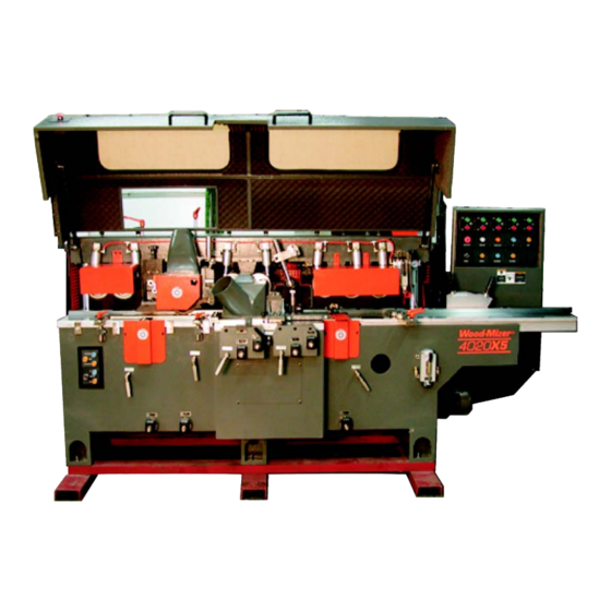
- Page 1 ® Wood-Mizer Moulder Safety & Operation Manual 4015X5 rev. A1.00+ 4020X5 rev. A1.00+ M485SP rev. A1.00+ Safety is our #1 concern! Read and understand all safety information and instructions before oper- ating, setting up or maintaining this machine. Form #1107...
-
Page 2: Table Of Contents
Table of Contents Section-Page ABOUT THIS MANUAL SECTION 1 SAFETY Safety Symbols..................1-1 Safety Instructions ..................1-2 SECTION 2 SETUP Moving The Moulder ................2-1 Installation ....................2-2 Electrical Installation................2-3 Air Installation..................2-4 SECTION 3 ADJUSTMENTS Cutting Head #1..................3-1 Vertical Adjustment...............3-1 Horizontal Adjustment ............3-2 Feed Table & Infeed Guides Adjustment..........3-3 Feed Table .................3-3 Infeed Guide Fence ...............3-3 Rear Infeed Guide Fence ............3-4... - Page 3 Table of Contents Section-Page SECTION 5 LUBRICATION AND MAINTENANCE SECTION 6 TROUBLESHOOTING Problems to the Processed Items and Remedies........6-1 Mechanical Problems ................6-4 SECTION 7 SPECIFICATIONS SECTION 8 ELECTRICAL INFORMATION Electrical Schematics................8-1 INDEX Table of Contents MO01doc091902...
-
Page 4: About This Manual
The information and instructions given in this manual do not amend or extend the limited warranties for the equipment given at the time of purchase. For general information regarding Wood-Mizer and our “Forest to Final Form” products, please refer to the All Products Catalog. - Page 5 MO0001 M4015X5 MOULDER About This Manual MO01doc091902...
-
Page 6: Safety
Safety Safety Symbols SECTION 1 SAFETY Safety Symbols The following symbols and signal words call your attention to instructions concerning your personal safety. Be sure to observe and follow these instructions. DANGER! indicates an imminently hazardous situation which, if not avoided, will result in death or serious injury. WARNING! suggests a potentially hazardous situation which, if not avoided, could result in death or serious injury. -
Page 7: Safety Instructions
It is always the owner's responsibility to comply with all applicable federal, state and local laws, rules and regulations regarding the ownership and operation of your Wood-Mizer machine. All Wood-Mizer machine owners are encouraged to become thoroughly familiar with these applicable laws and comply with them fully while using the machine. - Page 8 Safety Safety Instructions WEAR SAFETY CLOTHING WARNING! Secure all loose clothing, jewelry and long hair before operating the machine. Failure to do so may result in serious injury or death. WARNING! Always wear eye, ear, respiration, and foot protection when operating or servicing the machine. KEEP MACHINE AND AREA AROUND MACHINE CLEAN DANGER! Maintain a clean and clear path for all necessary move-...
- Page 9 Safety Safety Instructions KEEP HANDS AWAY DANGER! Always keep hands away from moving blades. Failure to do so will result in serious injury. DANGER! Always be aware of and take proper protective mea- sures against rotating shafts, pulleys, fans, etc. Always stay a safe distance from rotating members and make sure that loose clothing or long hair does not engage rotating members resulting in possi- ble injury.
- Page 10 Safety Safety Instructions SAFETY PRECAUTIONS DURING OPERATION WARNING! Inspect the material to be worked for embedded objects such as stones or nails. Feeding material with such objects may cause severe personal injury. WARNING! Do not leave the machine running. Turn the machine off and allow it to come to a full stop before leaving the site.
- Page 11 Safety Safety Instructions USE PROPER PROCEDURE WHEN CONDUCTING ELECTRICAL SAFETY CHECKS AND MAINTENANCE DANGER! Make sure all electrical installation, service and/or maintenance work is performed by a qualified electrician and is in accordance with applicable electrical codes. DANGER! Hazardous voltage inside the electrical cabinet can cause shock, burns, or death.
-
Page 12: Setup
Setup Moving The Moulder SECTION 2 SETUP Moving The Moulder See Figure 2-1. Transport the moulder with a forklift using the provided forklift skid. CAUTION! Be sure all cables and hoses are clear of the forks when moving the moulder. Failure to do so may cause damage to the machine. -
Page 13: Installation
Setup Installation Installation Unbolt the shipping skid from the moulder frame. Lift the moulder up and remove the skid. See Figure 2-2. Place the machine on a firm, level concrete surface at least 6 inches (150mm) thick. Place 3/8-inch (10mm) thick steel plates under each leg. Adjust the level- ing bolts to level the machine. -
Page 14: Electrical Installation
Setup Electrical Installation Electrical Installation DANGER! Make sure all electrical installation, service and/or maintenance work is performed by a qualified elec- trician and is in accordance with applicable electrical codes. Install an appropriately rated disconnect box near the machine and use proper cable/wiring to supply power to the moulder. -
Page 15: Air Installation
Setup Air Installation Air Installation See Figure 2-4. The moulder requires an air supply of 80 psi (minimum). Install a fitting to the air regulator and connect the air supply hose to the fitting. The regulator is set by the factory at 50 psi. -
Page 16: Adjustments
Adjustments Cutting Head #1 SECTION 3 ADJUSTMENTS The cutting heads are referred to as #1 - #5 starting at the front (infeed) end of the moul- der. Cutting Head #1 Vertical Adjustment Adjust cutting head #1 vertically so the blades are the same height as the fixed table behind the cutting head. -
Page 17: Horizontal Adjustment
Adjustments Cutting Head #1 turn the adjustment shaft clockwise to raise the blade, counterclockwise to lower the blade. NOTE: When lowering the blade, lower it further than desired then back up to remove slack from the adjusting screw. After adjusting cutting head #1 vertically, tighten the lock handle and reset the counter to zero. -
Page 18: Feed Table & Infeed Guides Adjustment
Adjustments Feed Table & Infeed Guides Adjustment Feed Table & Infeed Guides Adjustment Feed Table See Figure 3-3. Turn the feed table adjustment handle and lift or lower the table to the desired position. The number indicated on the handle is the distance relative to the fixed table behind cutting head #1 (in millimeters). -
Page 19: Rear Infeed Guide Fence
Adjustments Feed Table & Infeed Guides Adjustment Rear Infeed Guide Fence See Figure 3-4. Adjust the guide fence behind cutting head #2 so that it is 1/4” from the blades. Use a hex wrench to loosen the screws, adjust the fence and retighten the screws. -
Page 20: Cutting Head #2
Adjustments Cutting Head #2 Cutting Head #2 Horizontal Adjustment Adjust cutting head #2 so the blades are even with the rear infeed guide fence. This cut- ting head will be readjusted in or out depending on the side profile being used. See Figure 3-5. -
Page 21: Vertical Adjustment
Adjustments Cutting Head #2 Vertical Adjustment Use a finished sample piece of the moulding to be cut to determine the proper vertical position of cutting head #2. Lay the sample on the table against the guide fence in front of the cutting head. -
Page 22: Cutting Head #3
Adjustments Cutting Head #3 Cutting Head #3 Horizontal Adjustment Use a finished sample piece of the moulding to be cut to determine the proper horizontal position of cutting head #3. Lay the sample on the table against the guide fence in front of the cutting head. -
Page 23: Vertical Adjustment
Adjustments Cutting Head #3 Vertical Adjustment Using a finished sample of moulding as a guide, adjust cutting head #3 up or down as necessary. See Figure 3-8. Loosen the locking handle and use the supplied wrench handle to turn the adjustment shaft clockwise to raise the blade, counterclockwise to lower the blade. Retighten the locking handle and reset the counter to zero. -
Page 24: Rear Guide Fence & Chip Breaker/Roller Assembly
Adjustments Cutting Head #3 Rear Guide Fence & Chip Breaker/Roller Assembly Check that the rear guide fence behind cutting head #3 is parallel to the main guide fence. Measure the distance from both ends of the adjustable guide fence to the main guide fence. - Page 25 Adjustments Cutting Head #3 See Figure 3-10. Loosen the locking bolts and adjust the chip breaker/roller assembly so it touches the steel rule. Retighten the locking bolts. Loosen the horizontal locking bolt and adjust the assembly so the chip breaker is 1/4” from the blades. Retighten the locking bolt.
- Page 26 Adjustments Cutting Head #3 See Figure 3-11. Ring-shaped plates are provided to place in the recessed area around each cutter head. Use the plates when working small mouldings that may get caught in the recesses. Place two plates in position around each cutter head and secure with the provided screws.
-
Page 27: Cutting Head #4
Adjustments Cutting Head #4 Cutting Head #4 Vertical Adjustment Using a finished sample of moulding as a guide, adjust cutting head #4 up or down as necessary. See Figure 3-12. Loosen the locking handle and use the supplied wrench handle to turn the adjustment shaft clockwise to raise the blade, counterclockwise to lower the blade. -
Page 28: Horizontal Adjustment
Adjustments Cutting Head #4 Horizontal Adjustment Using a finished sample of moulding as a guide, adjust cutting head #4 in or out as nec- essary. See Figure 3-13. Loosen the locking handle and use the supplied wrench to turn the adjustment shaft clockwise to move the blade back, counterclockwise to move the blade forward. -
Page 29: Chip Breaker Adjustments
Adjustments Cutting Head #4 Chip Breaker Adjustments See Figure 3-14. Adjust the chip breaker in front of cutting head #4 so it is positioned 1/8” - 1/4” below the lowest portion of the profile blade. To adjust the front chip breaker verti- cally, loosen the two locking bolts and turn the adjustment handle. - Page 30 Adjustments Cutting Head #4 See Figure 3-15. Adjust the chip breaker behind cutting head #4 to within 1/8” - 1/4” from the blade. Turn the rear chip adjustment handle to raise or lower the rear chip breaker. Loosen the horizontal locking bolts to move the rear chip breaker toward or away from the blade.
-
Page 31: Cutting Head #5
Adjustments Cutting Head #5 Cutting Head #5 Vertical Adjustment Adjust cutting head #5 vertically so the blades are the same height as the fixed table behind the cutting head. See Figure 3-16. Place a flat steel rule on the fixed table so it extends over cutting head #5. -
Page 32: Horizontal Adjustment
Adjustments Cutting Head #5 Turn the locking handle counterclockwise to loosen. Use the supplied wrench handle to turn the adjustment shaft clockwise to raise the blade, counterclockwise to lower the blade. NOTE: When lowering the blade, lower it further than desired then back up to remove slack from the adjusting screw. -
Page 33: Hold-Down Roller Adjustment
Adjustments Hold-Down Roller Adjustment Hold-Down Roller Adjustment See Figure 3-18. Loosen the vertical clamp bolt to slide the hold-down roller up or down. Loosen the horizontal clamp bolt to move the hold-down roller in or out so it is centered on the workpiece. -
Page 34: Feed System Adjustments
Adjustments Feed System Adjustments Feed System Adjustments Feed Rollers See Figure 3-19. The feed rollers move up and down with the upper head. All of the feed rollers should be adjusted in the same vertical plane to apply equal pressure to the work- piece. -
Page 35: Feed Speed Adjustment
Adjustments Feed System Adjustments Feed Speed Adjustment See Figure 3-20. Turn the feed speed adjustment knob to select the appropriate feed rate as indicated by the gauge. Choose the highest speed possible that still allows the material to be cut smoothly. Low speed is required for thick cuts or when cutting hard wood. -
Page 36: Lower Feed Roller Adjustment
Adjustments Feed System Adjustments Lower Feed Roller Adjustment See Figure 3-21. The lower feed rollers are spring-loaded and should be adjusted to .005” above the table surface. To adjust the lower feed roller height, locate the adjust- ment bolt at the back of the machine. Turn the lower adjustment nut to raise or lower the rollers. -
Page 37: Auxiliary Guide Adjustments
Adjustments Auxiliary Guide Adjustments Auxiliary Guide Adjustments See Figure 3-22. Auxiliary guides are provided at the front and rear ends of the machine. To adjust the front guide, loosen the locking handles and slide the assembly in or out so the roller contacts the side of the workpiece. - Page 38 Adjustments Auxiliary Guide Adjustments See Figure 3-23. To adjust the rear guide, loosen the lock handles and slide the assem- bly in or out so the guide contacts the side of the workpiece. FIG. 3-23 3-23 MO01doc091902 Adjustments...
-
Page 39: Operation
Operation Control Description SECTION 4 OPERATION Control Description See Figure 4-1. The main control panel is located at the front of the machine. FIG. 4-1 See Table 4-1. A description of each control button on the main panel is provided below. Button/Light Description Power Lamp... -
Page 40: Preparing For Operation
Operation Preparing For Operation 1 - 5 Starts cutting heads 1 - 5. Push the green start button to start the corresponding cutting head. Push the red stop button to stop the corresponding cutting head. TABLE 4-1 See Figure 4-2. Auxiliary controls are located at the rear of the machine. The Emergency Stop and Feed control buttons operate exactly the same as the buttons on the main con- trol panel described above. -
Page 41: Test Run
Operation Test Run 3. Turn the blades manually to see if the blades touch other parts. Make adjustments as necessary. Test Run DANGER! Make sure all guards and covers are in place and secured before operating the machine. Remove all loose objects from the machine before operating. - Page 42 Operation Test Run 4. After all components are adjusted as desired, increase the feed speed as allowed by the material being processed. 5. When the operation is finished, turn the machine off. Disconnect the air supply to the machine, attach an OSHA approved nozzle and blow all sawdust from the moulder. WARNING! Do not leave the machine running.
-
Page 43: Lubrication And Maintenance
Lubrication & Maintenance SECTION 5 LUBRICATION AND MAINTENANCE See Table 5-1. Lubricate the machine as instructed in the table. Keep the surface of the machine clean, and keep all the rails clean. WARNING! Turn off the machine and lock out the electrical supply before performing service or maintenance to the machine. -
Page 44: Troubleshooting
Troubleshooting Problems to the Processed Items and Remedies SECTION 6 TROUBLESHOOTING Problems to the Processed Items and Remedies PROBLEM CAUSE SOLUTION Defects at the Lower Part of Over-low position of the Hori- Adjust the Blade Upward, or the Infeed Wood Material zontal Blade, or the Blade is Sharpen the Blade blunt... - Page 45 Problems to the Processed Items and Remedies PROBLEM CAUSE SOLUTION Defects on the Right Side of Over Back Position of the Blade Adjust the Blade forward, and the Infeed Wood Material Keep It at the Same Level with the Board Defects on the Right Side of Over-forward Position of the Adjust the Blade Backward, and...
- Page 46 Problems to the Processed Items and Remedies PROBLEM CAUSE SOLUTION The sides on the width direc- a. Blade not parallel with the a. Make renewed adjustment to tion not parallel platform or the ruler. the blade b. One of the blades are seri- b.
-
Page 47: Mechanical Problems
Mechanical Problems Mechanical Problems Problems Causes And Remedies 1. The wood materials can not be feed in, or stopped A) Examine the electric layouts and electric after feeding in, or can not be fed in smoothly. machine. B) Check if the wheels and chain to the speed transformer work normally. -
Page 48: Specifications
Specifications SECTION 7 SPECIFICATIONS See Table 7-1. Specifications for 4015x5/4020x5 Models: Specification Model 4015x5 Model 4020x5 Machine Dimensions 116” L x 58” W x 61” H 126” L x 60” W x 61” H (2.95m x 1.48m x 1.56m) (3.2m x 1.54m x 1.55m) Maximum Material Capacity 5.90”... - Page 49 7.5 HP (5.5kW) Spindle RPM 6000 Spindle Bearings 40mm FAG (Germany) Cutter Blocks 40mm x 125mm diameter Cutter Knives (Corrugated) High-Speed Steel (Replacements, re-grinding, or profiles available from Wood-Mizer) Required air flow for dust 5000 cfm (100m3) removal TABLE 7-2 Specifications MO01doc091902...
-
Page 50: Electrical Information
Electrical Information Electrical Schematics SECTION 8 ELECTRICAL INFORMATION Electrical Schematics FIG. 8-1 (PAGE 1 OF 3) MO01doc091902 Electrical Information... - Page 51 Electrical Information Electrical Schematics FIG. 8-1 (PAGE 2 OF 3) Electrical Information MO01doc091902...
- Page 52 Electrical Information Electrical Schematics FIG. 8-1 (PAGE 3 OF 3) MO01doc091902 Electrical Information...
- Page 53 INDEX adjustments auxiliary guides 3-22 chip breaker 3-14 feed system 3-19 feed table & infeed guides front vertical blade hold-down roller 3-18 infeed roller 3-19 rear lower blade 3-16 rear vertical blade upper blade horizontal 3-13 maintenance lubrication operation preparation test run safety instructions...
Need help?
Do you have a question about the 4015X5 and is the answer not in the manual?
Questions and answers