Table of Contents
Advertisement
Quick Links
GETTING STARTED GUIDE
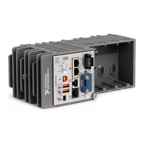
NI cRIO-9034
Embedded CompactRIO Controller with Real-Time Processor and
Reconfigurable FPGA
This document describes how to begin using the National Instruments cRIO-9034.
Safety Guidelines
Caution
Product misuse can result in a hazard. You can compromise the safety protection
built into the product if the product is damaged in any way. If the product is
damaged, return it to NI for repair.
Safety Guidelines for Hazardous Locations
The cRIO-9034 is suitable for use in Class I, Division 2, Groups A, B, C, D, T4 hazardous
locations; Class I, Zone 2, AEx nA IIC T4 and Ex nA IIC T4 hazardous locations; and
nonhazardous locations only. Follow these guidelines if you are installing the cRIO-9034 in a
potentially explosive environment. Not following these guidelines may result in serious injury
or death.
Do not operate the cRIO-9034 in a manner not specified in this document.
Advertisement
Table of Contents

Subscribe to Our Youtube Channel
Related Manuals for National Instruments cRIO-9034


Summary of Contents for National Instruments cRIO-9034
- Page 1 Safety Guidelines for Hazardous Locations The cRIO-9034 is suitable for use in Class I, Division 2, Groups A, B, C, D, T4 hazardous locations; Class I, Zone 2, AEx nA IIC T4 and Ex nA IIC T4 hazardous locations; and nonhazardous locations only.
-
Page 2: Special Conditions For Hazardous Locations Use In Europe And Internationally
All cables must be used in a conduit or cable gland to wire to a nonhazardous location. Do not disconnect a cable unless the cRIO-9034 is powered off or the area is known to be nonhazardous. -
Page 3: Electromagnetic Compatibility Guidelines
Refer to the following sections for more information. Related Information Connecting the cRIO-9034 to Ground on page 7 Connecting the cRIO-9034 to Power on page 8 NI cRIO-9034 Getting Started Guide | © National Instruments | 3... -
Page 4: Special Conditions For Marine Applications
In addition, take precautions when designing, selecting, and installing measurement probes and cables to ensure that the desired EMC performance is attained. Preparing the Environment Ensure that the environment in which you are using the cRIO-9034 meets the following specifications. Operating temperature -20 °C to 55 °C... -
Page 5: Verifying The Kit Contents
2. USB A-to-B Cable 3. Ferrite (x2) Installing Software on the Host Computer Before using the cRIO-9034, you must install the following application software and device drivers on the host computer in this order: LabVIEW 2014 or later LabVIEW Real-Time Module 2014 or later... -
Page 6: Removing C Series Modules
Verify that power is not connected to the I/O connector(s) on the C Series module. If the system is in a nonhazardous location, the cRIO-9034 can be powered on when you install modules. Press the latches on the C Series module. - Page 7 6. Ground Screw 13. USB Device Port 7. USER1 Button 14. Power and Reset Buttons Connecting the cRIO-9034 to Ground You must connect the cRIO-9034 grounding terminal to the grounding electrode system of the facility. What to Use • Ring lug •...
- Page 8 C Series modules. The cRIO-9034 has a primary power input, V1, and a secondary power input, V2. The POWER LED on the cRIO-9034 indicates which power input is in use, as shown in the following table.
- Page 9 (24 VDC, 5 A, 100 VAC to 120 VAC/200 VAC to 240 VAC input) What to Do Complete the following steps to connect a power supply to the cRIO-9034. Ensure that your power supply is powered off. Install the ferrite on the negative and positive leads of the power supply, as shown in the following figure.
- Page 10 Power on the primary power supply and optional secondary power supply. Powering On the cRIO-9034 When you power on the cRIO-9034 for the first time, the device boots into safe mode. The POWER LED illuminates, the STATUS LED illuminates briefly, and then the STATUS LED blinks twice every few seconds.
-
Page 11: Setting A System Password
The device driver software automatically detects the cRIO-9034. If the device driver software does not detect the cRIO-9034, verify that you installed the appropriate NI software in the correct order on the host computer. You can also use the Ethernet port to connect directly to the host computer or network. - Page 12 Click Next. Select NI Scan Engine from the software add-ons. Select any additional software to install. If you plan on using the cRIO-9034 with the LabVIEW FPGA Module, you can click Next. Click NI Scan Engine if you plan on using the cRIO-9034 without the LabVIEW FPGA Module.
-
Page 13: Verify The System Ip Configuration
Set a new DHCP connection by holding the RESET button down for 5 seconds. The STATUS LED repeats the same behavior from Step If the cRIO-9034 fails to set a new DHCP address, it assigns itself a link-local IP address. If the DHCP connection is successful and appropriate for your application, skip to Step In MAX, expand your system under Remote Systems. -
Page 14: System Reset
Ensure that UDP port 44525 is open to communication on the host computer. If you are using an intelligent switch on the network, ensure that it is not disabling UDP port 44525. System Reset The following figure shows the reset behavior of the cRIO-9034. Figure 5. Reset Button Behavior Press and hold RESET button for <... - Page 15 Remove any shorts and cycle power the cRIO-9034. If the problem persists, contact NI. — The cRIO-9034 is in run mode. Software is installed and the operating system is running. NI cRIO-9034 Getting Started Guide | © National Instruments | 15...
-
Page 16: Where To Go Next
Worldwide Support and Services The National Instruments website is your complete resource for technical support. At ni.com/ support, you have access to everything from troubleshooting and application development self-help resources to email and phone assistance from NI Application Engineers. - Page 17 National Instruments corporate headquarters is located at 11500 North Mopac Expressway, Austin, Texas, 78759-3504. National Instruments also has offices located around the world. For telephone support in the United States, create your service request at ni.com/support dial 1 866 ASK MYNI (275 6964). For telephone support outside the United States, visit the Worldwide Offices section of ni.com/niglobal...
- Page 18 Other product and company names mentioned herein are trademarks or trade names of their respective companies. For patents covering National Instruments products/technology, refer to the appropriate location: Help»Patents in your software, the file on your media, or the National Instruments Patent Notice at .
Need help?
Do you have a question about the cRIO-9034 and is the answer not in the manual?
Questions and answers