Advertisement
Quick Links
Electrical Specifications, T
Parameter
Frequency Range
Gain Variation Over Temperature
(‐40℃~+85℃)
Input Return Loss
Output Return Loss
Saturated Output Power (Psat)
Isolation S12
Input Max Power (No Damage)
Impedance
Power Supply Connector
Input / Output Connectors
Material
Rev 2. 01‐11‐2021
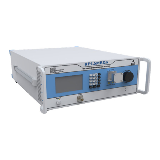
400W 8-11GHz EMC-Benchtop
Solid State Power Amplifier
℃
=25
A
Gain
Weight
Features
•
Automatic Calibration
•
Built in Temperature Compensation
•
Adjustable Attenuation:
31.5dB Range, 0.5dB Step Size
•
Supply Voltage: 110V/220V AC
Typical Applications
•
Aerospace and military applications
•
Test and Measurement.
•
Research and Development.
Min.
Typ.
8 ‐ 11
56
±3
15
20
55
‐
Psat – Gain
560
50
D‐SUB COMBO 3POS
Input SMA‐Female or N‐type Female ‐‐‐ Output N‐Type Female
Aluminum / Copper
REMC08G11GE
Max.
Units
GHz
dBm
dBm
ounces
Ohms
RF-LAMBDA USA
Sales: sales@rflambda.com
Technical : support@rflambda.com
dB
dB
dB
dB
dB
www.rflambda.com
Advertisement

Related Manuals for RF-Lambda REMC08G11GE


Summary of Contents for RF-Lambda REMC08G11GE
- Page 1 REMC08G11GE 400W 8-11GHz EMC-Benchtop Solid State Power Amplifier Features • Automatic Calibration • Built in Temperature Compensation • Adjustable Attenuation: 31.5dB Range, 0.5dB Step Size • Supply Voltage: 110V/220V AC Typical Applications • Aerospace and military applications • Test and Measurement. • Research and Development. ℃ Electrical Specifications, T Parameter Min. Typ. Max. Units Frequency Range 8 ‐ 11 Gain Gain Variation Over Temperature ±3 (‐40℃~+85℃) Input Return Loss Output Return Loss...
- Page 2 REMC08G11GE Absolute Maximum Ratings Biasing Up Procedure Supply Voltage 110V 220v AC Connect input and output with 50 Ohm Step 1 source/load. ( in band VSWR<1.9:1 or >10dB RF Input Power (RFIN) Psat – Gain return loss) Pin_max = Psat ‐ Gainsat Step 2 Turn on AC power. Step 3 Enable RF output Power OFF Procedure Step 1 Turn off RF output power Step 2 Turn Off AC power Step 3 Disconnect input and output Environmental Specifications and Test Standards Parameter Description ‐40℃~+85℃ Operational Temperature (Case Temperature) Storage Temperature ‐50℃~+105℃ ‐40℃ +85℃ Thermal Shock (5 Cycles / 10 hours) MIL‐STD‐202G...
- Page 3 REMC08G11GE Ordering Information Part No. Description REMC08G11GE 8GHz~11GHz Power Amplifier Amplifier Use Ensure that the amplifier input and output ports are safely terminated into a proper 50 ohm load before turning on the power. Never operate the amplifier without a load. A proper 50 ohm load is defined as a load with impedance less than 1.9:1 or return loss larger than 10dB relative to 50 Ohm within the specified operating band width.
- Page 4 REMC08G11GE Typical Performance Plots Gain Gain vs. Output Power Saturation Power vs. Frequency RF-LAMBDA USA www.rflambda.com Rev 2. 01‐11‐2021 Sales: sales@rflambda.com Technical : support@rflambda.com...
-
Page 5: Front Panel
REMC08G11GE EMC Equipment User Manual Front Panel ON/OFF switch Display Keypad Gain Adjustment Knob RF Output RF Input Rear Panel Instrument AC power supply switch Fuse Holder Main AC connector GND connector USER CONTROL, D‐SUB Connector low‐voltage (3.3V) TTL control signals. See page below for more information. USB Port (upon request) LAN Port (upon request) RF-LAMBDA USA www.rflambda.com Rev 2. 01‐11‐2021 Sales: sales@rflambda.com Technical : support@rflambda.com... - Page 6 REMC08G11GE Front Panel LCD Screen Display Switching On Instrument Please follow the instructions on the front panel LCD screen after switching on the power. Press “1” on keypad to continue. Self Calibration Screen Calibration is may be recommended “[1] Calibrate” to execute instrument self calibration process. “[2] Reset” to reboot the instrument. *Please turn OFF RF input power, and terminate the RF output port while applying calibration function Instrument Protection Alarms The front panel LCD screen will display the error code or error message when instrument self protection is triggered. Front panel alarm indicator will light up. To eliminate the error code, press “RESET” on front panel keypad to reboot the instrument and clear the alarms. If error code can not be eliminated after reboot, please contact support@rflambda.com RF-LAMBDA USA www.rflambda.com Rev 2. 01‐11‐2021 Sales: sales@rflambda.com Technical : support@rflambda.com...
- Page 7 REMC08G11GE Instrument Status Display Page Indicates instrument RF output status. It will display: Output is Ready to Turn on or RF Output is ON Instrument temperature RF output attenuation (change with adjustment knob) RF input signal center frequency Instrument RF output power Press “Menu” on keypad to enter instrument functions selection menu User can set a constant gain for the unit. Equipment will automatically adjust the gain at certain frequency Switches On or Off for instrument RF output port Instrument Function Selection Page To enter this function selection page, press “Menu” on front panel keypad while the instrument is showing the status page. Press the corresponding number on front panel keypad to select: “[1] Calibrate” calibrates the instruments. “[2] Frequency” enters RF input signal center frequency. “[3] RF ON/OFF” switches the RF output port on or off. “[4] Reset” Restarts the instrument (Turns RF output off) “[5] Status” enters instrument status display page. “[6] Product Info” displays product part number and serial number All action functions will ask for confirming execution when selected from function selection menu. RF-LAMBDA USA www.rflambda.com Rev 2. 01‐11‐2021 Sales: sales@rflambda.com Technical : support@rflambda.com...
- Page 8 REMC08G11GE User Control Connector on Rear Panel Pin # Name Function Initial State Description Applied Reset Control Resets PA when logic LOW is applied and released Yes Driver Disable Control Appling logic HIGH disables driver of amplifiers Drain Disable Control Applying logic HIGH disables drain of amplifiers Pin will be latched to logic HIGH when input signal is RF IN Over Indicator over limit Pin will be latched to logic HIGH when amplifier is Temp Over Indicator driven over temperature Pin will be latched to logic HIGH when drain current Current Over Indicator limit is reached Pin will be latched to logic HIGH when an imbalance in ID Imbalance Indicator the drain current of the combining branches occurs...
-
Page 9: Amplifier Outline Drawing
REMC08G11GE Amplifier Outline Drawing: All Dimensions in mm [inches] 425 [16.73] PN:REMC08G11GE Freq:8-11GHz 25 [0.98] 25 [0.98] 25 [0.98] 60 [2.36] 68 [2.68] 77 [3.03] 160 [6.3] 173.4 [6.83] 421.4 [16.59] 460 [18.11] 192.7 [7.59] 160 [6.3] 27 [1.06] 43 [1.69] 40 [1.57] 40 [1.57] 18 [0.71] 24.25 [0.95]...
Need help?
Do you have a question about the REMC08G11GE and is the answer not in the manual?
Questions and answers