urmet domus 1730 Installation And Instruction Manual
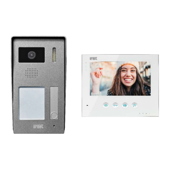
2-wire single-family hands-free colour kit
Hide thumbs
Also See for 1730:
- Installation and instruction manual (30 pages) ,
- Quick start manual (2 pages) ,
- Installation (2 pages)

Related Manuals for urmet domus 1730


Summary of Contents for urmet domus 1730
- Page 1 Mod. 1730 DS1730-010 2-WIRE SINGLE-FAMILY HANDS-FREE COLOUR KIT Ref. 1730/501 Installation and instruction manual...
-
Page 2: Table Of Contents
Basic kit diagram ....................16 Connection of 3 apartment stations in parallel ............16 Summary of basic 1730/501 kit features ............... 17 Summary of default settings.................. 17 LED 1 and 2 indications on basic systems with kit only ........18 Maximum distances between devices .............. -
Page 3: Warnings
WARNINGS Read the notes in this manual carefully. This manual contains important information on safe installation, use and maintenance. GENERAL WARNINGS This device is only intended for the specifically designed use. All other use is improper. The manufacturer cannot be held responsible for damage deriving from improper, incorrect or unreasonable use. -
Page 4: Description
DESCRIPTION The 1730 system can be used to create video door phone systems for from one-family to four-family houses with only two non-polarised wires and a power supply unit. Starting from the basic kit, consisting of a outdoor station, a video door phone and a power supply unit, the system can be expanded up to its maximum capacity without adding further power units. -
Page 5: Device Performance And Overview
APARTMENT STATIONS 7” colour video door phone Ref. 1730/1 and audio door phone Ref. 1730/2, both soft touch and hands-free. LED for identifying the call source. Possibility of connecting up to 4 door units in parallel in the same apartment. -
Page 6: Video Door Phone
VIDEO DOOR PHONE 14 15 ICONS AND FUNCTIONS Ring tone mute LED Open lock LEDs for outdoor station 1 or 2 Activate additional contact Microphone Audio button Turn camera on Settings SETTINGS Brightness Conversation volume Colour Call volume REAR VIEW Speaker Slot for WiFi module Bracket hooks... -
Page 7: Video Door Phone Installation
VIDEO DOOR PHONE INSTALLATION The video door phone includes a dedicated bracket for installation directly on the wall or in a flush-mounting box type 503 (recommended choice) or in a round 60 mm diameter box. Fix the bracket at a height of about 1.5 m from the ground with the appropriate anchor bolts. Use the available locations by placing the UP sign at the top: INSTALLATION IN 503 INSTALLATION IN 60 mm... -
Page 8: Connections
The video door phone connections and the configuration dip switches are located on the back of the video door phone (the basic kit 1730/501 does not require any changes to the default configuration for installation). DESCRIPTION OF TERMINAL BOARD AND CONNECTOR J10... -
Page 9: Outdoor Station
Urmet Ref. 1096/405 or other CVBS camera * Access control module connection Ref. 1730/65 * A mean current of 300mA, up to 500 mA peak and a voltage of 12 Vdc, are available on the outdoor station for powering a CCTV camera. -
Page 10: Outdoor Station Installation
FLUSH-MOUNTED INSTALLATION The accessory Ref. 1730/60, not included in the kit, is available for flush-mounted installation. It consists of a box to be recessed into the wall, on which there are several holes for running the wires a plate on which to screw the front block. -
Page 11: Name Tag Inscription
NAME TAG INSCRIPTION DS1730-010... -
Page 12: Connections
2 Lock control time = 300 ms BACK ON AFTER 3 Key programming = OFF EACH CHANGE TO (see manual of the 1730/65 module) THE DIP SWITCHES 4 Video standard = PAL AND JUMPERS 5 and 6 Total buttons = 1 7 ... - Page 13 Jumper JP4 must be removed when adding an external camera. Otherwise keep it in the default position. See the instructions supplied with the individual devices to expand the system with another outdoor station (Ref. 1730/51) or with additional call buttons (2-4 button kit Ref. 1730/102-104) or for integrating the access control module (Ref. 1730/65). ...
-
Page 14: Installing The External Camera
INSTALLING THE EXTERNAL CAMERA A camera can be integrated in the 1730 system to monitor the external environment. The camera can be picked from the Urmet CCTV catalogue with CVBS operating mode (12Vdc power, max. average consumption 300 mA), for example a AHD DAY & NIGHT CAMERA 4MPX 2.8mm WITH IR LED, Ref. - Page 15 Set-up for Urmet camera Ref. 1096/405 in CVBS For operation with the 1730 system, CVBS video mode must be selected on the camera. To do this: Press the button on the video door phone several times (see the "Video surveillance"...
-
Page 16: 1730 System Connection Examples
1730 SYSTEM CONNECTION EXAMPLES BASIC KIT DIAGRAM The 1730/501 kit is ready for installation using the following diagram. There is no need to modify the dip switches and jumpers on the devices. VIDEO DOOR PHONE CONNECTION OF 3 APARTMENT STATIONS IN PARALLEL The following devices are needed for this installation: video door phones 1730/1 or door phones 1730/2. -
Page 17: Summary Of Basic 1730/501 Kit Features
SUMMARY OF BASIC 1730/501 KIT FEATURES See the next chapter for a detailed description of the individual functions. CALL FROM THE OUTDOOR Press the call button on the STATION AND LIGHTING OF outdoor station (see basic THE VIDEO DOOR PHONE... -
Page 18: Led 1 And 2 Indications On Basic Systems With Kit Only
ADDITION OF ACCESSORIES FOR SYSTEM EXPANSION Simplified dip-switch programming is available to configure an extended system with additional accessories. Installation can be made easier with the optional use of a distributor Ref. 1730/54, which can replace or supplement inlet-outlet or star wiring on device terminals. -
Page 19: Extension Example: Single-Family System With 2 Outdoor Stations
10.1 EXTENSION EXAMPLE: SINGLE-FAMILY SYSTEM WITH 2 OUTDOOR STATIONS The following devices are needed for this installation: Outdoor Station Ref. 1730/51, Urmet camera Ref. 1096/405 or generic in CVBS mode (see details in the section dedicated to the outdoor station). -
Page 20: Extension Example. Two-Family System With 2 Users
EXTENSION EXAMPLE. TWO-FAMILY SYSTEM WITH 2 USERS The following devices are needed for this installation: 2-button kit with name tag for two 1730/102 users. Camera Urmet Ref. 1096/405 or generic camera in CVBS mode (see details in the section dedicated to the outdoor station). -
Page 21: 11 System Operation
11 SYSTEM OPERATION 11.1 EXTERNAL CALL The kit video door phone emits the call tone and the display lights up when a call is received from door. In expanded systems with several apartment stations, all the devices present will emit the call tone and the display will light up on the video door phones. -
Page 22: Activation Of Contacts On The Outdoor Station
11.2 ACTIVATION OF CONTACTS ON THE OUTDOOR STATION In stand-by mode, the controls (lock release) and (contact activation) are not active. With the display on, the two controls become operational. CONTROL ACTIVATION AFTER CONTROL ACTIVATION FOLLOWING ACTIVATING THE DISPLAY A CALL FROM THE OUTDOOR STATION PRESS THE BUTTONS CORRESPONDING TO THE CONTROL YOU WANT TO ACTIVATE... -
Page 23: Video Surveillance Systems
11.3 VIDEO SURVEILLANCE SYSTEMS When not in use and without having received any call, the video door phones can display the external environment filmed by the outdoor station cameras and by any additional cameras. Use the camera power button to activate video surveillance. By pressing the button in succession, outdoor station 1, any external camera connected to it, outdoor station 2 (if present) and finally any external camera connected to it are displayed in sequence. -
Page 24: Audio Line Activation
11.4 AUDIO LINE ACTIVATION Press the video surveillance button on the video door phone to activate the audio line with the outdoor station. After switching on the display, press the audio button on the video door phone to start a conversation or simply to activate environmental listening: Environmental listening Conversation with the outside... -
Page 25: Intercom Service Between Apartment Stations
11.6 INTERCOM SERVICE BETWEEN APARTMENT STATIONS The system offers the possibility of establishing a conversation between the video or audio door phones in an apartment. The service is only available if additional internal apartment stations are added. With the system standing by, press the audio activation button, the other apartment stations present will ring at the same time: Press the audio button on any of the ringing apartment stations to start the intercom conversation. - Page 26 DIRECTIVE 2012/19/EU OF THE EUROPEAN PARLIAMENT AND OF THE COUNCIL of 4 July 2012 on waste electrical and electronic equipment (WEEE). The crossed-out wheelie bin symbol on the equipment or its packaging indicates that the product at the end of its useful life must be collected separately from other waste. Therefore, any products that have reached the end of their useful life must be given to waste disposal centres specialising in separate collection of waste electrical and electronic equipment.
- Page 27 DS1730-010...
- Page 28 DS1730-010 URMET S.p.A. Technical Assistance 011-3986712 10154 TORINO (ITALY) http://www.urmet.com VIA BOLOGNA 188/C email: assistenza@urmet.com Tel. +39 0112400000 (AUTO) DS1730-010 Made in China to URMET specifications...
Need help?
Do you have a question about the 1730 and is the answer not in the manual?
Questions and answers