Table of Contents
Advertisement
Quick Links
Mod.
1736
DS1736-024
LBT21485
SINGLE-FAMILY 2-WIRE EXPANDABLE
HANDS-FREE COLOR KIT
Ref. 1736/511
Installation and instruction manual
Para el manual completo de este dispositivo, escanea el código QR
Para o manual completo deste dispositivo, faça o scan do código QR
Für das vollständige Handbuch dieses Geräts scannen Sie den QR-Code
Για το πλήρες εγχειρίδιο αυτής της συσκευής, σαρώστε τον κωδικό QR
Për manualin e plotë të kësaj pajisjeje, skanoni kodin QR
ﻟﻠﺤﺼﻮل ﻋﻠﻰ اﻟﺪﻟﯿﻞ اﻟﻜﺎﻣﻞ ﻟﮭﺬا اﻟﺠﮭﺎز، ﻗﻢ ﺑﻤﺴﺢ رﻣﺰ اﻻﺳﺘﺠﺎﺑﺔ اﻟﺴﺮﯾﻌﺔ ﺿﻮﺋ ﯿ ً ﺎ
Advertisement
Table of Contents

Subscribe to Our Youtube Channel
Related Manuals for urmet domus 1736/511


Summary of Contents for urmet domus 1736/511
- Page 1 DS1736-024 LBT21485 SINGLE-FAMILY 2-WIRE EXPANDABLE HANDS-FREE COLOR KIT Ref. 1736/511 Installation and instruction manual Para el manual completo de este dispositivo, escanea el código QR Para o manual completo deste dispositivo, faça o scan do código QR Für das vollständige Handbuch dieses Geräts scannen Sie den QR-Code Για...
-
Page 2: Table Of Contents
1736 SYSTEM CONNECTION EXAMPLES ............. 17 Basic kit diagram ....................17 Additional devices connection diagram ..............17 Summary of basic 1736/511 kit features ............... 18 Summary of default settings .................. 18 Led 1 and 2 indications on basic systems with kit only ......... 19 Maximum distances between devices .............. -
Page 3: Warnings
WARNINGS Read the notes in this manual carefully. This manual contains important information on safe installation, use and maintenance. This device is only intended for the specifically designed use. • All other use is improper. The manufacturer cannot be held responsible for damage deriving from •... -
Page 4: Description
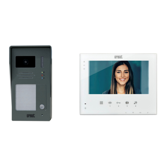
4 users. The system is equipped with an intercom system via the door phones and the video door phones in the same apartment. The basic kit 1736/511 contains: Outdoor station with color camera 7” soft touch hands-free video door phone... -
Page 5: Device Performance And Overview
DEVICE PERFORMANCE AND OVERVIEW OUTDOOR STATION Wall-mounted with rain cover and color camera as standard. Possibility of up to 4 calling buttons on the outdoor station of the kit. Activation of a 12V lock with pedestrian gate button. Piloting of a driveway via dry contact. Light signals on front indicating the call as well as the conversation in progress and lock opening. -
Page 6: Video Door Phone
VIDEO DOOR PHONE FRONT VIEW System led Active outdoor station L1 L2 Ring tone mute Function buttons Turn camera on Audio button Open lock Relay module 1736/70 activation (which enables operation of buttons Additional contact 1-2-3-4) Microphone Led use relay LOWER VIEW Settings Brightness... -
Page 7: Video Door Phone Installation
VIDEO DOOR PHONE INSTALLATION The video door phone includes a dedicated bracket for installation directly on the wall or in a flush-mounting box type 503 (recommended choice) or in a round 60 mm diameter box. Fix the bracket at a height of about 1.5 m from the ground with the appropriate anchor bolts. Use the available locations by placing the UP sign at the top: INSTALLATION IN 503 INSTALLATION IN 60 mm... -
Page 8: Connections
CONNECTIONS The video door phone connections and the configuration dip switches are located on the back of the video door phone (the basic kit 1736/511 does not require any changes to the default configuration for installation). IN-OUT TERMINAL BLOCK DIP SWITCH 1-6... -
Page 9: Dip Switch Setting
DIP SWITCH SETTING USER NUMBER DIP SWITCH No. 1-3 POSITION USER N° FOR FUTURE USES DIP SWITCH No. 4 Dip switch for future uses Leave OFF END OF LINE DIP SWITCH No. 5 LINE closure The video door phone does Only on last indoor location on not have line closure single user system... -
Page 10: Outdoor Station
OUTDOOR STATION SYSTEM STATUS FUNCTIONS Camera Name tag Rain hood Courtesy LED Call button Wall fastening screw seat Speaker Microphone Terminal board / Dip-switch SYSTEM STATUS LEDS Opening of gate connected to the outdoor station Meaning of the light Yellow Call forwarding from outdoor station to indoor user signals Conversation in progress between indoors and... -
Page 11: Outdoor Station Installation
OUTDOOR STATION INSTALLATION Wall-mounted installation Rain hood Unscrew the screw indicated in the figure to the side, to unlock the front of the pushbutton panel from the rain cover. Position the rain cover at the recommended height Front block (side panel) and with the hole provided in correspondence with the passage of the cables. -
Page 12: Name Tag Inscription
NAME TAG INSCRIPTION DS1736-024... -
Page 13: Connections
CONNECTIONS Connection and configurations are available on the rear side of the front block. To access the connections undo the screw holding the front block to the hood, as described above REAR SIDE OF THE FRONT BLOCK Terminal board P2 connector for camera connection Dip switch P4 connector... -
Page 14: Dip Switch Settings Summary
DIP SWITCH SETTINGS SUMMARY OFF: the outdoor station is No. 1. ON: the outdoor station is No. 2. Line 1 will be used Line 2 will be used OFF: the duration of the control ON: the duration of the control pulse for opening the lock is pulse for opening the lock is 4 300ms... -
Page 15: Installing The External Camera
300 mA), for example a AHD DAY & NIGHT CAMERA 4MPX 3.6mm WITH IR LED, Ref. 3300/410 or 3300/510. In kit 1736/511, supplied with the outdoor station, a 3-wire cable is supplied which must be inserted in connector P2 on the rear of the outdoor station (see Connections chapter):... - Page 16 * Recommended accessories To connect the wires coming from the outdoor station to those of the camera, we recommend the use of adapters of the type exemplified below. Use a 75 Ω coaxial cable for the video signal from the camera. Coaxial cable adapter with Power adapter with male male BNC connector...
-
Page 17: 1736 System Connection Examples
1736 SYSTEM CONNECTION EXAMPLES BASIC KIT DIAGRAM The 1736/511 kit is ready for installation. There is no need to modify the dip switches and jumpers on the devices. ADDITIONAL DEVICES CONNECTION DIAGRAM Connection of video door phones 1736/1 or door phones 1736/2, parallel to the video door phone of the kit. -
Page 18: Summary Of Basic 1736/511 Kit Features
SUMMARY OF BASIC 1736/511 KIT FEATURES Basic kit connection The call from the outdoor station activates switch-on of the video door phone display. Pressing call button Pressing the button a second time cancels the call in progress. With video door phone on... -
Page 19: Led 1 And 2 Indications On Basic Systems With Kit Only
LED 1 AND 2 INDICATIONS ON BASIC SYSTEMS WITH KIT ONLY LED signalling Receiving calls from the outdoor station L1 or L2 Slow flashing Conversation with outdoors or pressing button L1 or L2 On fixed activate audio/video on the outdoor station Receiving a floor call Slow flashing Stand-by... -
Page 20: Addition Of Accessories For System Expansion
A summary table of the dip switch configuration is available for each additional device. The single-family system with basic kit 1736/511 does not require any configuration changes. It is already prepared for operation after the appropriate connection has been made. -
Page 21: Single-Family System With 2 Outdoor Stations
SINGLE-FAMILY SYSTEM WITH 2 OUTDOOR STATIONS For this system, include: supplementary outdoor station ref. 1736/51, Urmet camera 3300/410, 3300/510 or generic in CVBS mode (see the details in the dedicated section of this manual). Second internal video door phone ref. 1736/1 or door phone 1736/2. ... -
Page 22: External Call
EXTERNAL CALL The kit video door phone emits the call tone and the display lights up when a call is received from door. If there are multiple internal devices, all the devices in the apartment will emit the call tone and only the master video door phone will have the display on. -
Page 23: Activation Of Contacts On The Outdoor Station
ACTIVATION OF CONTACTS ON THE OUTDOOR STATION In stand-by mode, the controls (lock release) and (contact activation) are not active, while the control is always enabled to close the 4 relay contacts. With the display on, the two controls become operational. -
Page 24: Video Surveillance Systems
VIDEO SURVEILLANCE SYSTEMS When not in use and without having received any call, the video door phones can display the external environment filmed by the outdoor station cameras and by any additional cameras (Video surveillance). The service activates by pressing the button on the video door phone (the camera on the outdoor station switches on). -
Page 25: Audio Line Activation
AUDIO LINE ACTIVATION Press the video surveillance button on the video door phone to activate the audio line with the outdoor station. After switching on the display, press the audio button on the video door phone to start a conversation or simply to activate environmental listening: oppure Environmental listening... -
Page 26: Intercom Service Between Apartment Stations
INTERCOM SERVICE BETWEEN APARTMENT STATIONS The system offers the possibility of establishing a conversation between the video or audio door phones in an apartment. The service is only available if additional internal apartment stations are added. With the system standing by, press the audio activation button, the other apartment stations present will ring at the same time: Press the audio button on any of the ringing apartment stations to start the intercom conversation. - Page 27 DIRECTIVE 2012/19/EU OF THE EUROPEAN PARLIAMENT AND OF THE COUNCIL of 4 July 2012 on waste electrical and electronic equipment (WEEE). The symbol of the crossed-out wheeled bin on the product or on its packaging indicates that this product must not be disposed of with your other household waste. Instead, it is your responsibility to dispose of your waste equipment by handing it over to a designated collection point for the recycling of waste electrical and electronic equipment.
- Page 28 LBT21485 DS1736-024 URMET S.p.A. Customer Service 011-19620654 10154 TORINO (ITALY) http://www.urmet.com VIA BOLOGNA 188/C assistenza@urmet.com DS1736-024 Telef. +39 011.24.00.000 Made in China...
Need help?
Do you have a question about the 1736/511 and is the answer not in the manual?
Questions and answers