
Related Manuals for Panametrics PM880 AC


Summary of Contents for Panametrics PM880 AC
- Page 1 Process Analyzers Model PM880 AC Portable Hygrometer User’s Manual 910-268 B panametrics.com August 2021...
- Page 3 Flow Model PM880 AC Portable Hygrometer User’s Manual 910-268 Rev. B August 2021 panametrics.com Copyright 2021 Baker Hughes company. This material contains one or more registered trademarks of Baker Hughes Company and its subsidiaries in one or more countries. All third-party product and company names are trademarks of their respective...
- Page 4 [no content intended for this page]...
- Page 5 Make sure that operators and maintenance personnel have all safety equipment applicable to the auxiliary equipment. Examples include safety glasses, protective headgear, safety shoes, etc. Unauthorized Operation Make sure that unauthorized personnel cannot gain access to the operation of the equipment. Model PM880 AC User’s Manual...
- Page 6 Environmental Compliance Waste Electrical and Electronic Equipment (WEEE) Directive Panametrics Measurement & Control Solutions is an active participant in Europe’s Waste Electrical and Electronic Equipment (WEEE) take-back initiative, directive 2002/96/EC. The equipment that you bought has required the extraction and use of natural resources for its production. It may contain hazardous substances that could impact health and the environment.
-
Page 7: Table Of Contents
Shutting Down the Sample System ................14 Chapter 3. Using the PM880 AC Screen Screen Components. - Page 8 Sorting Files in the Site/Drive/Log Manager ..............54 Chapter 7. Using the PM880 AC with a PC and Printer Setting Up PM880 AC IR Communications .
- Page 9 Sample System Guidelines ..................97 Chapter B. Menu Maps Model PM880 AC User’s Manual...
- Page 10 Contents viii Model PM880 AC User’s Manual...
-
Page 11: Chapter 1. Getting Started
1.1.1 Powering On To turn the PM880 AC on, press the red button in the upper-right-hand corner of the keypad. Immediately upon powerup the PM880 AC displays a series of messages and performs various checks. The screen then appears similar to the one shown in Figure 1. -
Page 12: Powering Off
Chapter 1. Getting Started 1.1.2 Powering Off To turn the PM880 AC off, press the red key for 3 seconds. The screen now appears similar to Figure 2.Press [F1] to shut down the PM880 AC. Figure 2: Shutdown Menu Entering Data Using the Keypad Use the information below to familiarize yourself with how to enter data using the PM880 AC keypad. -
Page 13: Entering Calibration Data
Calibration Data Sheets are usually packed inside the probe cases. Since the PM880 AC enables you to use more than one probe, the meter provides a place to enter the probe serial number to help you match the probes to the corresponding site files. The probe serial number is stored as part of the site file. - Page 14 You need to enter calibration data for M and TF Series probes only. The Moisture Image Series (MIS) probes store all calibration data in their electronics module, and upload it into the PM880 AC memory when needed. Note: It is not necessary to enter calibration data for the Moisture Image Series (MIS) probe unless you send it back to the factory for calibration without its electronics module.
- Page 15 Use the arrow key to scroll to Program and press [ENTER]. Use the arrow key to scroll to Calibrate and press [ENTER]. Use the arrow key to scroll to Pressure and press [ENTER]. The screen appears similar to Figure 6. Model PM880 AC User’s Manual...
- Page 16 The span mV box is highlighted. Repeat steps 5, 6 and 7 to enter the Span values. When you have completed entering values, press [F3] (Exit). 10. Press [F3] (OK) and proceed to Displaying Measurements . Model PM880 AC User’s Manual...
-
Page 17: Displaying Measurements
Chapter 1. Getting Started Displaying Measurements The PM880 AC can display one to four measurement parameters simultaneously. There are two parts for displaying measurements: selecting the number of measurements and then selecting the type of measurements. See Figure 9 on page 17 for a menu map. -
Page 18: Saving Data In A Site File
• Press [F3] (Yes) if you do want to use it as a template. If you are saving a new file as a template, the PM880 AC will ask if you want to Save Current Site , press [F2] Note: ( No ) or [F3] ( Yes ). - Page 19 Chapter 1. Getting Started Figure 9: Startup Menu Model PM880 AC User’s Manual...
- Page 20 Chapter 1. Getting Started [no content intended for this page] Model PM880 AC User’s Manual...
-
Page 21: Chapter 2. Taking Measurements
Chapter 2. Taking Measurements Chapter 2. Taking Measurements The PM880 AC hygrometer is part of a measurement system that includes the electronics, cable, probe and optional sample system. Once the electronics are properly programmed, you must connect the sample system and probes to begin taking measurements. -
Page 22: Connecting The Sample System To The Process
5 to 15 feet (1.5 to 4.5 m). A male NPT process connection is provided. Figure 11: The Sample System and the PM880 AC Making Probe Connections Use the following steps to make probe connections: Make sure the PM880 AC is turned off. -
Page 23: Recalling A Site File
Figure 12: Connection Locations WARNING! TO ENSURE THE SAFE OPERATION OF THE PM880 AC, YOU MUST INSTALL AND OPERATE IT AS DESCRIBED IN THIS MANUAL. IN ADDITION, BE SURE TO FOLLOW ALL APPLICABLE SAFETY CODES AND REGULATIONS FOR INSTALLING ELECTRICAL EQUIPMENT IN YOUR AREA. -
Page 24: Conducting A Leak Test
Chapter 2. Taking Measurements Turn on the PM880 AC. Figure 13: Sample System Valve Locations Conducting a Leak Test It is important to eliminate all leaks for safety reasons and to be sure that measurements are not affected by ambient contamination. Use Snoop Leak Detector or a soapy solution to verify that all connections, valves and fittings are leak tight. -
Page 25: Chapter 3. Using The Pm880 Ac Screen
Chapter 3. Using the PM880 AC Screen Chapter 3. Using the PM880 AC Screen Use the sections that follow to setup and make adjustments to the PM880 AC screen. This chapter discusses the following: • Screen Components - page 16 •... -
Page 26: Screen Components
Screen Components The PM880 AC screen displays various information (see Figure 14). The top line of the screen is the status bar that displays the current site, time, and date during normal operation. However, the status bar changes to a menu bar during programming. -
Page 27: Setting Up The Screen To Display Measurements
Setting Up the Screen to Display Measurements The PM880 AC can display one to four measurements simultaneously. After you select how many measurements to display, you can select the type of measurements (dewpoint, temperature, etc.) and the format (numeric, line or bar graph). -
Page 28: Selecting Numeric, Line Or Bar Graph Format
Repeat steps 3 and 4 for Decimal Places or proceed to the next step to exit. You can select from 0 to 4 places. Press [F3] (OK). The PM880 AC displays the new format and resumes taking measurements. Model PM880 AC User’s Manual... -
Page 29: Adjusting The Line/Bar Graph Scale
Creating Function Key Shortcuts The three function keys at the bottom of the PM880 AC screen can be customized to provide shortcuts to the most commonly used functions. For example, the F1 key can be assigned to go directly to the Log Manager. Once assigned, a function key can also be cleared. -
Page 30: Clearing A Function Key
Using the Backlight The PM880 AC has a backlight that helps in viewing data. Since the backlight uses more energy, the PM880 AC has a backlight timer that can be set to automatically turn the backlight off after a specified time. The PM880 AC also enables you to turn the backlight on and off manually. -
Page 31: Adjusting The Contrast
• To File - to send the snapshot to a file. Note: In order to send a screen capture to a printer, the PM880 AC must be properly configured to IR transfer. Refer to Setting Up the PM880 AC IR Communications on page 56. - Page 32 Chapter 3. Using the PM880 AC Screen [no content intended for this page] Model PM880 AC User’s Manual...
-
Page 33: Chapter 4. Using Special Features
Chapter 4. Using Special Features The PM880 AC has a variety of other features to make operation even more convenient. Below are some of the features available. For other features related to testing and service functions, refer to Chapter 8, Maintenance and Troubleshooting . -
Page 34: Selecting English Or Metric Units
Entering Date and Time The PM880 AC displays the current date and time above the measurements in the upper right corner of the screen. The Date/Time command enables you to set the date or time. The current date and time are required for correct data logging operation. -
Page 35: Selecting The Separator
Repeat steps 1 and 2 for the time format. Press [F3] (OK) and then press [MENU]. The PM880 AC returns to taking measurements. The new date and time formats are displayed. Adding a Message to a Site File The Site Manager has a command that enables you to enter a message or description for each site file (up to 30 characters). -
Page 36: Entering Probe Information
Use the arrow keys to move to Cal Reminder and press [ENTER]. This prompt asks you to select a time period for the next probe calibration. The PM880 AC will display a calibration reminder for the probe based on the last calibration date. -
Page 37: Entering Constants And User Functions
• To exit and return to taking measurements, press [F3] (OK) and then [MENU]. Entering Constants and User Functions The PM880 AC enables you to enter two types of constants, a user constant and a saturation constant, as well as user-defined functions and tables to manipulate data. -
Page 38: Entering A User Constant
4.8.1 Entering a Saturation Constant The PM880 AC requires a saturation constant in order to calculate ppm in non-aqueous liquids. If you do not know the saturation constants of the process liquid sample, contact the factory. To enter a saturation constant (Cs), you must enter 1 to 8 data points to represent a curve of Cs (values) versus temperature. - Page 39 Next, do one of the following: • Use the arrow keys to scroll to another tab and program additional data (if available, depending on probe type). • To exit and return to taking measurements, press [F3] (OK) and then [MENU]. Model PM880 AC User’s Manual...
-
Page 40: Entering User Functions
[ENTER]. Press [SEL] to view additional character selections and symbols for creating a label for the function. Repeat this procedure until you have created the desired units symbol for the function of up to thirty-two characters. When you have finished, press [F3] (OK). Model PM880 AC User’s Manual... - Page 41 Figure 26: Function Creation Window When you have finished entering the equation, press [F3] (OK). Press [F2] (Check) to test the validity of the function. The PM880 AC displays either “OK” or a message such as “Syntax Error.” Do one of the following: •...
-
Page 42: Setting Up User Tables
Setting Up User Tables To support user-defined functions, the PM880 AC can hold up to 6 tables of non-linear or empirical data. Users can enter up to 21 X-Y pairs in each table. The user functions can supply an X value with Table (X). The meter then interpolates the Y value for a given X, and substitutes it for Table (X) in the function. -
Page 43: Using Computer Enhanced Response
If the menu is not active, press [MENU]. Use the arrow key to scroll to Program and press [ENTER]. Use the arrow key to scroll to System and press [ENTER]. A screen similar to Figure 29 on page 34 appears. Model PM880 AC User’s Manual... -
Page 44: Response Time Procedure
The PM880 AC will display the actual dewpoint temperature during the initial dry-down. The display will indicate a bold “E” in the system tray which means the PM880 AC is in CER mode. After 2 to 5 minutes, the PM880 AC will perform its initial predicted calculation of the equilibrium dewpoint temperature. -
Page 45: 4.10 Entering Reference Data
Note: If the dewpoint temperature increases to a wetter value during the dry down, the PM880 AC may not report a prediction and the bold “E” will remain on the display. This indicates an unstable moisture content in the gas. -
Page 46: Resuming Operation
Press [F2] to place the PM880 AC in Sleep Mode. Figure 31: Shutdown Menu 4.11.2 Resuming Operation Tap the red power key. The PM880 AC powers on, performs an AutoCal and returns to exactly where you left it. Model PM880 AC User’s Manual... -
Page 47: 4.12 Displaying Meter Information
Press [F2] (Next) to list additional data such as the boot program, instrument program, FPGA (timing) program, language, help version, serial number and PCI number. Press [F3] (Exit) and then press [MENU]. The PM880 AC returns to taking measurements. Model PM880 AC User’s Manual... -
Page 48: 4.13 Changing The Display Language
The PM880 AC user program is available in several languages. To change the language: Note: The PM880 AC defaults to US English. However, one or more alternate languages can be installed at any time. Consult your Panametrics representative or www.bakerhughes.com for available languages. -
Page 49: Chapter 5. Logging Data
Chapter 5. Logging Data Data logging is one of the PM880 AC’s most powerful and flexible features. The meter enables you to choose up to 12 measurements to log. Logs can run one at a time or simultaneously. Error and circular logs are also available. The logged data is internally stored in memory. -
Page 50: Entering A Log Name
If you choose to run a circular log, you will need to enter the number of records you want to log instead of an Note: end date and time. Use the arrow keys to move to the Measurements tab and press [ENTER]. A screen similar to Figure 36 appears. Figure 36: Log Measurements Window Model PM880 AC User’s Manual... -
Page 51: Selecting A Measurement To Log
The PM880 AC returns to taking measurements. A Pencil icon appears in the bottom right-hand side of the screen. Pausing a Log The PM880 AC has two commands to pause logs: Pause and Pause All Logs. The PM880 AC can only pause logs that are currently running. -
Page 52: Starting Or Restarting A Log
Note: The PM880 AC also has an Pause command that enables you to stop the log temporarily. See Pausing a Log on page 41. Use the following steps to start or restart one or more logs: 5.4.0.1... -
Page 53: Viewing All Logs
Viewing Log Setup Details The PM880 AC enables you to view more than the log details shown in Log Manager. The Details command enables you to see the log status, date and time, length, interval, types of measurements logged and service information. -
Page 54: Displaying Logged Data
Displaying Logged Data The PM880 AC enables you to view logged data in a graph or spreadsheet format. Graphs and spreadsheets are set up in the Log Manager. Use the steps below to access the Log Manager and view logged data. - Page 55 • To view logs using the spreadsheet format, press [F3] (Exit), then press [MENU] and proceed to Using the Spreadsheet Format on page 46. • To exit and return to taking measurements, press [F3] (Exit) twice and then press [MENU]. Model PM880 AC User’s Manual...
-
Page 56: Using The Spreadsheet Format
The Enter Time window appears. Use the arrow keys to scroll to the desired text box. Press [ENTER] to open the box. Use the numeric keys to enter the desired number and press [ENTER]. Repeat steps 1 and 2 for other entries. Model PM880 AC User’s Manual... - Page 57 Chapter 5. Logging Data When you have finished, press [F3] (OK) to exit and view the spreadsheet. The PM880 AC displays the data nearest the time entered. Next, do one of the following: • To return to the Log Manager and view another log, press [F3] (Exit) and then press [MENU]. Return to Using the Graph Format on page 44.
- Page 58 Chapter 5. Logging Data Model PM880 AC User’s Manual...
-
Page 59: Chapter 6. Managing Files
The Site and Log Managers have additional commands for printing and all the Managers have the ability to transfer files to and from a PC. For more details on these functions refer to Chapter 7, Using the PM880 AC with a PC and Printer. -
Page 60: Recalling A Site File
When you have finished, press [F3] (OK). The PM880 AC prompt asks you if you want to save the site as a template. Saving the site file as a template is useful when you need to create multiple sites with similar data. At the prompt, do one of the following: •... -
Page 61: Renaming A Site File
• To exit and return to taking measurements, press [F3] (Exit) and then press [MENU]. The newly renamed site file is displayed in the upper left corner of the screen. Note: The PM880 AC uses the renamed site file to take measurements. To recall a different site file, refer to Recalling a Site File on page 50. 6.4.2 Renaming a Log File Use the steps below to rename a log file. -
Page 62: Copying A Log
Repeat this procedure until you have created the desired log name of up to eight characters. When you have finished, press [F3] (OK). The PM880 AC renames the file and returns to the Log Manager. Next, do one of the following: •... - Page 63 Use the arrow keys to scroll to the desired measurement type and press [SEL]. Use the arrow keys to scroll to the desired units and press [F3] (OK). Repeat steps 1 through 3 for up to 12 different parameters. Model PM880 AC User’s Manual...
-
Page 64: Deleting All Types Of Files
Chapter 6. Managing Files When you have finished, press [F3] (Activate) to start the log. The PM880 AC returns to the Log Manager. The log will begin at the specified date and time. Next, do one of the following: • To copy another log, repeat the steps beginning in Selecting a Log File on page 52. -
Page 65: Chapter 7. Using The Pm880 Ac With A Pc And Printer
Chapter 7. Using the PM880 AC with a PC and Printer The PM880 AC has the ability to transfer files to and from a PC. Both the Site Manager and Drive Manager have a transfer command that allows you to select a file and beam it to and from the PC and the PM880 AC. The Site Manager has an additional command that enables you to send site files to a printer. -
Page 66: Setting Up Pm880 Ac Ir Communications
The PM880 AC is already setup for IrDA (Infrared Data Association) infrared communications. Most PCs and devices use the IrDA protocol and the PM880 AC should not need to be reconfigured. If necessary, the PM880 AC can also be configured for IR232 communications. - Page 67 Chapter 7. Using the PM880 AC with a PC and Printer Figure 46: Welcome Screen Click Next. On the next screen, choose “Add/Troubleshoot a device” and click Next. Figure 47: Choose a Hardware Task Screen Windows will search, but will not find anything. Allow the search to complete.
- Page 68 Chapter 7. Using the PM880 AC with a PC and Printer Figure 48: New Hardware Detection Screen When the search finishes, you will see the dialog screen as in Figure 49. Choose “Add a new device,” and click Next. Figure 49: Choose a Hardware Device Screen On the next screen, choose “No, I want to select the hardware from a list,”...
- Page 69 Chapter 7. Using the PM880 AC with a PC and Printer Figure 50: Find New Hardware Screen Select Infrared Devices from the list, and click Next. Figure 51: Hardware Type Screen Select ACTiSYS and IR-220L+ Serial Infrared Device, and click Next.
- Page 70 Chapter 7. Using the PM880 AC with a PC and Printer Figure 52: Select Infrared Device Screen Windows supplies the appropriate driver, so click Next. Figure 53: Start Hardware Installation Screen 10. Select the Com port to which the IR adapter is attached.
- Page 71 Figure 54: Select the Communications Port Screen The IR support should then be installed automatically. 11. Place the IR adapter in front of the PM880 AC. You should hear a "bong" and the following message will pop up: Figure 55: Another Available Computer Message At this point, you can transfer files from the PM880 AC to the PC using its Site Manager/Log Manager/Drive Manager or by using PanaView.
-
Page 72: Using Panaview
Figure 56: PanaView Meter Browser 7.1.2 Using Panaview Panametrics offers PanaView software that enables you to perform many PM880 AC functions using your computer. With PanaView software (version 1.4.6 or greater), the communication connection is made automatically using IrOBEX (IR Object Exchange). - Page 73 IMPORTANT: Baud rate, parity, stop bits and data bits are active only when IR232 is selected for the communication interface. IR232 requires the following parameters: 9600, None, 1 and 8 respectively. Press [F3] (OK) and then press [MENU]. The PM880 AC returns to taking measurements. Model PM880 AC User’s Manual...
-
Page 74: Transferring And Printing Files Key
The PM880 AC indicates that it is searching for a receiving printer. If it spots more than one compatible infrared device within its range, it asks you to select the desired device. Once the PM880 AC finds the printer, it asks you to confirm, press [F3] (Yes) and then press [MENU]. The PM880 AC returns to the Site Manager. -
Page 75: Printing A Log File
Figure 58: Enter Time Window Make sure the IR beam on the PM880 AC has clear access to the IR sensor on the printer and press [F3] (OK). The PM880 AC indicates that it is searching for a receiving printer and then sends the file. If it spots more than one compatible infrared device within its range, it asks you to select the desired device. -
Page 76: Printing Reports
You can use the Site Manager, Drive Manager or the Log Manager to transfer files to your PC. The Site Manager enables you to transfer site files only; the Drive Manager enables you to transfer any file in the PM880 AC; and, the Log Manager enables you to transfer log files only. - Page 77 When the upload is complete, the meter returns to the Site/Drive/Log Manager. IMPORTANT: If the PM880 AC cannot detect an infrared device, a window appears indicating this problem. Reposition the PM880 AC and press [F3] Yes. Consult the factory if the PM880 AC is unable to make contact with your PC.
-
Page 78: Transferring A File From A Pc
Transferring a File from a PC The PM880 AC enables you to transfer site (.sit) and meter (.met) files from your PC to the meter. If you rename another type of file with one of these extensions and transfer it, it will be transferred, but will not function if you open it. - Page 79 Chapter 7. Using the PM880 AC with a PC and Printer Select the desired file and click on Send . A window appears indicating the file is downloading. Figure 61: Wireless Link Window Model PM880 AC User’s Manual...
- Page 80 Chapter 7. Using the PM880 AC with a PC and Printer [no content intended for this page] Model PM880 AC User’s Manual...
- Page 81 Chapter 8. Maintenance and Troubleshooting Chapter 8. Maintenance and Troubleshooting The PM880 AC is designed to be maintenance and trouble free. However, because of process conditions and other factors, minor problems may occur. The PM880 AC provides commands to monitor and check its various components.
-
Page 82: Chapter 8. Maintenance And Troubleshooting
Checking the PM880 AC Memory Status The PM880 AC stores all types of files in its memory. Each type of Manager enables you to monitor the size of a file and the remaining amount of memory. Use the following steps to check the memory status: 8.1.0.1... -
Page 83: Testing The Keypad
Press [F3] and then [MENU] to return to taking measurements. If any key does not appear on the screen, contact the factory. Testing the Watchdog Timer Circuit The PM880 AC includes a watchdog timer circuit. If a software error causes the meter to stop responding, this circuit automatically resets the meter. If the menu is not active, press [MENU]. -
Page 84: Resetting To Factory Default Settings
Use the arrow keys to scroll to Watchdog Test and press [ENTER]. The screen appears similar to Figure 64. Figure 64: Watchdog Test Screen Press [F3] (Yes) to start the test. The PM880 AC screen becomes blank for a few seconds and then begins the boot sequence. If it does not follow this sequence, consult the factory. -
Page 85: Viewing Or Changing Security Settings
Chapter 8. Maintenance and Troubleshooting The PM880 AC replaces the default site file and the global meter settings with the factory default settings. When the meter returns to taking measurements, it displays data using the default site. Viewing or Changing Security Settings To guard against accidental or intentional tampering, the PM880 AC includes a password-based security system. -
Page 86: Setting Remote Access Security
Use the arrow keys to move to Security Level and press [ENTER] to open the drop-down menu. Scroll to the desired level and press [ENTER]. The PM880 AC may ask you to enter a passcode depending on the level you choose. Enter the passcode and press [ENTER]. -
Page 87: Updating Pm880 Ac Software
Updating PM880 AC Software As discussed in Chapter 7, Using the PM880 AC with a PC or Printer , the PM880 AC uses an IR transceiver to transfer files. The IR function can also be used to upgrade the meter’s user program. The software upgrade includes the bootloader and instrument software, and the meter and Help string files. -
Page 88: Updating Software Using Irobex
The meter asks for confirmation. Press [F3] (OK) to continue with the update. After the PM880 AC reboots, the meter will ask you a series of questions. Use the appropriate function key to respond, then refer to the next section. - Page 89 The meter asks for confirmation. Press [F3] (OK) to continue with the update. After the PM880 AC reboots, the meter will ask you a series of questions. Use the appropriate function key to respond, then refer to the next section.
-
Page 90: Error And Screen Messages
Error and Screen Messages The PM880 AC has a series of error messages that display on the screen when the error occurs. The error messages are only general descriptions of the possible problems. The PM880 AC also has several screen messages that appear during operation and setup. - Page 91 AutoCal, or a probe failure is interfering with AutoCal. Err 25: The MIS Probe has not The PM880 AC will try to send No Data responded, or a data; wait for next update. calculation is not yet complete.
-
Page 92: Common Problems
Common Problems If the PM880 AC measurement readings seem strange, or they do not make sense, there may be a problem with the probe or a component of the process system. Table 5 contains some of the most common measurement problems. - Page 93 (158°F). Stream particles Probe reads Return the probe to the factory for causing abrasion. too wet or evaluation. too dry Symptom: Screen always reads the wettest (highest) programmed moisture calibration value while displaying dew/frost point. Model PM880 AC User’s Manual...
- Page 94 Hygrometer . Then reinstall sensor. Improper cable Check the cable connections to connection. both the probe and the PM880 AC. Symptom: Screen always reads the driest (lowest) programmed moisture calibration value while displaying dew/frost point. Open circuit on sensor. Return probe to factory for evaluation.
-
Page 95: 8.10 Replacing And Recalibrating The Moisture Probes
Contact a Panametrics applications engineer for the recommended calibration frequency for your application. You can program the PM880 AC to remind you when it is time to send the probes back for recalibration. Refer Note: to Setting a Probe Calibration Reminder on page 25. - Page 96 Chapter 8. Maintenance and Troubleshooting [no content intended for this page] Model PM880 AC User’s Manual...
-
Page 97: Chapter 9. Features And Specifications
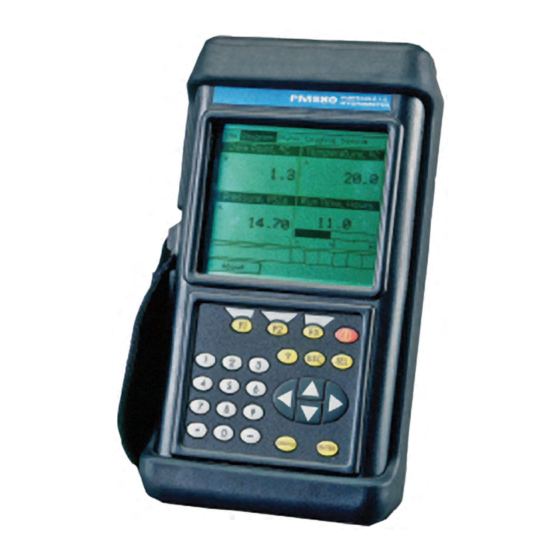
The PM880 AC Hygrometer The center of the measurement system is the PM880 AC hygrometer. The front of the meter has a Liquid Crystal Display, a membrane keypad and menu keys. See Figure 72. Figure 72: PM880 AC Hygrometer The top of the PM880 AC (shown in Figure 73) includes an input for connecting moisture probes. -
Page 98: M Series And Tf Series Moisture Probes
Chapter 9. Features and Specifications Probes are the part of the system that come into contact with the process flow. The PM880 AC uses various types of probes to make moisture, temperature, and pressure measurements. Note: Only Panametrics standard probes can be used with the PM880 AC. - Page 99 68°F) dew/frost point temperature and optionally from –110°C to 60°C (–166°F to 140°F). In addition, it can be used to measure temperature in a range of –30°C to 70°C (–22°F to 158°F) and pressure 30–300/50–500/100–1000/300– 3000/500–5000 psig. Model PM880 AC User’s Manual...
-
Page 100: Cabling
The M and the TF Series probes are connected to the analyzer with a special Panametrics shielded cable. Probes can be located up to 600 meters (2,000 feet) from the PM880 AC (consult the factory for distances up to 1,200 meters). To measure pressure with a TF probe, the maximum cable length is approximately 152 meters (500 feet). -
Page 101: Operational
Output: 7.5 VDC, 690 mA, 5.2 W European Compliance Complies with EMC Directive 2004/108/EC For EN61000-4-3, the PM880 AC meets performance criteria A and in a limited number of frequencies, performance criteria B per EN61326. EN 61326-2-3: 2006 Model PM880 AC User’s Manual... -
Page 102: Moisture Measurement
Compatible with all Panametrics aluminum-oxide moisture probes: M Series, TF Series and Moisture Image Series. Each probe type requires a different type of I/O cable. Calibration Panametrics moisture sensors are computer calibrated to NIST-traceable moisture concentrations. Dew/frost Point Temperature Overall Range Capability •... -
Page 103: Sample System
120 to 240 VAC battery charger. Printer dimensions: 6.3 6.5 2.3 in. (160 164 59 mm). Weight: 13 oz (370 g). Print width: 4 in. (104 mm). • PC Interface Software - PanaView™ Graphical User Interface. Model PM880 AC User’s Manual... - Page 104 Chapter 9. Features and Specifications [no content intended for this page] Model PM880 AC User’s Manual...
-
Page 105: Chapter A. Measurement Considerations
There are a variety of environmental and installation factors that can affect measurements. These factors should be discussed with a Panametrics applications engineer or field sales person by the time you receive the PM880. However, if you decide to add additional measurement sites, this section contains some basic guidelines for selecting a measurement site and constructing a sample system. - Page 106 The sensor will operate properly in a multitude of gaseous or non-conductive liquid environments. g. Corrosive Materials Avoid all materials that are corrosive or otherwise damaging to aluminum or aluminum oxide. These include strongly acidic or basic materials and primary amines. Model PM880 AC User’s Manual...
-
Page 107: Sample System Guidelines
They may also allow ambient contamination to enter the sample stream. In general, you should use stainless steel material for all wetted parts. Contact the Panametrics PCI Division at 1-800-833-9438 (within the USA) or 781-899-2719 (outside the USA) for further instructions. - Page 108 Chapter A. Measurement Considerations Model PM880 AC User’s Manual...
- Page 109 Chapter B. Menu Maps Chapter B. Menu Maps This chapter includes menu maps of the PM880 AC program. Refer to the following: • The Site Menu - page 101 • The Program Menu - page 102 • The Meter Menu - page 103 •...
- Page 110 Chapter B. Menu Maps Model PM880 AC User’s Manual...
-
Page 111: Chapter B. Menu Maps
N otes : P re ss [F 2] (C a n cel) to c an cel th e e n trie s a nd re tu rn to M e nu . P re ss [F3 ] (O K ) to c on firm the en tries an d return to M en u. Figure 78: Site Menu Model PM880 AC User’s Manual... - Page 112 Pre ss [F 3 ] (O K ) to co n firm th e e n trie s a n d re tu rn to M en u . E q u a tio n Figure 79: Program Menu Model PM880 AC User’s Manual...
- Page 113 Sto p B its YY Y Y/M M M M /D D D D /M M T im e F orm a t D ata Bits 12 H ou r 2 4 H our Figure 80: Meter Menu Model PM880 AC User’s Manual...
- Page 114 P re ss [F 3 ] (O K ) to co nfirm th e e n tries an d re turn to M e n u . S ta n da rd E rror S tart E n d In te rva l M e asu re m en t Figure 81: Logging Menu Model PM880 AC User’s Manual...
- Page 115 P ress [F2 ] (C a nce l) to can cel the e ntries a nd return to M enu. P ress [F3 ] (O K ) to con firm the en tries and return to M enu. Figure 82: Service Menu Model PM880 AC User’s Manual...
- Page 116 Appendix B. Menu Maps Model PM880 AC User’s Manual...
- Page 117 Shutting Down the Sample System 14 Deleting Files 54 Site Selection 95 Description IR Adapter 56 Error Messages 80 IR Communications Screen 2 Changing Parameters 56, 64, 66, 68 Diagnostics, Error Messages 80 Keypad, Testing 73 Language Option 38 Model PM880 AC User’s Manual...
- Page 118 Screen 16 Bitmap Screen Capture 21 Software,Updating 77 Contrast, Adjust 21 Power Date and Time Appearance, Changing 24 Sleep Mode 35 Description 2 Turning On and Off 1 Language, Changing 38 Selecting Format 18 Testing 72 Model PM880 AC User’s Manual...
- Page 119 Time Changing Appearance 24 Entering 24 Transferring Files from a PC 68 Transferring Files to a PC 66 Troubleshooting, Error Messages 80 Turning On/Off 1 Units Option 24 Updating Software 77 User Constants, Entering 27 Model PM880 AC User’s Manual...
- Page 120 Index Model PM880 AC User’s Manual...
- Page 121 Notify Panametrics Sensing, giving full details of the problem, and provide the model number and serial number of the instrument. If the nature of the problem indicates the need for factory service, Panametrics will issue a RETURN AUTHORIZATION NUMBER (RAN), and shipping instructions for the return of the instrument to a service center will be provided.
- Page 122 Warranty [no content intended for this page] Model PM880 AC User’s Manual...
- Page 124 Customer Support Centers U.S.A. The Boston Center 1100 Technology Park Drive Billerica, MA 01821 U.S.A. Tel: 800 833 9438 (toll-free) 978 437 1000 E-mail: mstechsupport@bakerhughes.com Ireland Sensing House Shannon Free Zone East Shannon, County Clare Ireland Tel: +35 361 470291 E-mail: mstechsupport@bakerhughes.com Copyright 2021 Baker Hughes company.
Need help?
Do you have a question about the PM880 AC and is the answer not in the manual?
Questions and answers