
Related Manuals for Rockwell Automation Allen-Bradley 1794-IRT8


Summary of Contents for Rockwell Automation Allen-Bradley 1794-IRT8
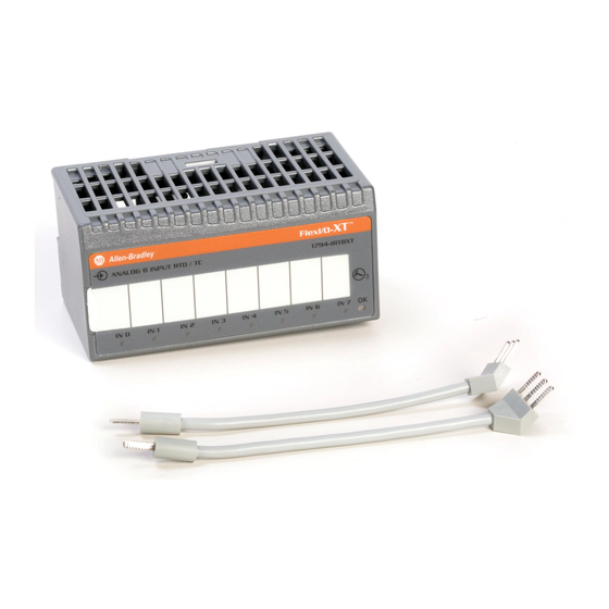
- Page 1 FLEX I/O Thermocouple/RTD/ Millivolt Input Module Catalog Numbers 1794-IRT8,1794-IRT8XT User Manual Original Instructions...
- Page 2 If this equipment is used in a manner not specified by the manufacturer, the protection provided by the equipment may be impaired. In no event will Rockwell Automation, Inc. be responsible or liable for indirect or consequential damages resulting from the use or application of this equipment.
-
Page 3: Table Of Contents
Series A Functionality in a Series B Module ........33 Rockwell Automation Publication 1794-UM012D-EN-P - March 2023... - Page 4 ..............57 Rockwell Automation Publication 1794-UM012D-EN-P - March 2023...
-
Page 5: Preface
Describes basic Ethernet concepts, infrastructure components, and infrastructure features. Industrial Automation Wiring and Grounding Guidelines, publication 1770-4.1 Provides general guidelines for installing a Rockwell Automation industrial system. Product Certifications website, rok.auto/certifications Provides declarations of conformity, certificates, and other certification details. - Page 6 Preface Notes: Rockwell Automation Publication 1794-UM012D-EN-P - March 2023...
-
Page 7: Overview Of Flex I/O And Your
-40.00 mV… +100.00 mV or 0.0…500.0 Ω. Fault indicators are located field side. No switches or jumpers are used on the TC and RTD Input module. The inputs have both fixed hardware filters and selectable firmware digital filters. Rockwell Automation Publication 1794-UM012D-EN-P - March 2023... -
Page 8: What The Flex I/O Input Module Does
Your ladder program can use “and/or” to move the data (if valid) before it is overwritten by the transfer of new data in a subsequent transfer. New configuration data can be sent to the module anytime during operation. Rockwell Automation Publication 1794-UM012D-EN-P - March 2023... -
Page 9: Physical Features Of Your Module
Power on indicator Input designators (1) Studio 5000 Logix Designer is the replacement for RSLogix 5000® (version 20 or later). It provides one software package for discrete, process, batch, motion, safety, and drive-based applications. Rockwell Automation Publication 1794-UM012D-EN-P - March 2023... - Page 10 Chapter 1 Overview of FLEX I/O and Your Thermocouple, RTD, and Millivolt Input Module Notes: Rockwell Automation Publication 1794-UM012D-EN-P - March 2023...
-
Page 11: Install Your Flex I/O Input
• If a CJC temperature is overrange or underrange the associated CJC Alarm bit is set. In this condition, the CJC Status bit is not set. • The CJC Status bit did not exist in Series A. Rockwell Automation Publication 1794-UM012D-EN-P - March 2023... -
Page 12: Power Requirements
Installation of the FLEX I/O module consists of: • Mounting the terminal base unit • Installing the Thermocouple, RTD, and mV module into the terminal base unit • Installing the connecting wiring to the terminal base unit Rockwell Automation Publication 1794-UM012D-EN-P - March 2023... -
Page 13: Mount On A Din Rail
5. Rotate the terminal base onto the DIN rail with the top of the rail hooked under the lip on the rear of the terminal base. Make sure that the female Flexbus connector does not strike any of the pins in the mating connector. Rockwell Automation Publication 1794-UM012D-EN-P - March 2023... -
Page 14: Mount On A Panel Or Wall
If you are installing your module into a terminal base unit that is already installed, proceed to Mount the FLEX I/O Module on the Terminal Base Unit on page Use the mounting kit Catalog Number 1794-NM1 for panel or wall mounting. Rockwell Automation Publication 1794-UM012D-EN-P - March 2023... - Page 15 6. Position the terminal base unit up against the adapter and push the female bus connector into the adapter. 7. Secure to the wall with two #6 self-tapping screws. 8. Repeat for each remaining terminal base unit. Rockwell Automation Publication 1794-UM012D-EN-P - March 2023...
-
Page 16: Mount The Flex I/O Module On The Terminal Base Unit
Make sure that the last terminal base has the cap plug in place. IMPORTANT The adapter is capable of addressing eight modules. Do not exceed a maximum of eight terminal base units in your system. Rockwell Automation Publication 1794-UM012D-EN-P - March 2023... -
Page 17: Wiring Information
One of the leads in each pair is the compensation lead. Either lead of the pair can be the compensation lead. Attach one pair to terminals L and -, and the other pair to + and H. Rockwell Automation Publication 1794-UM012D-EN-P - March 2023... - Page 18 Allow 2 minutes for settling time after finishing connections. • If using RTD isolators, use 2- or 4-wire configurations only, and add digital filtering to the inputs. Rockwell Automation Publication 1794-UM012D-EN-P - March 2023...
- Page 19 ATTENTION: Keep exposed area of inner conductor as short as possible. Figure 8 - Millivolt Wiring to a 1794-TB3G Terminal Base Unit Millivolt source Millivolt source Millivolt source Millivolt source 13 14 0...15 16...33 34...51 Rockwell Automation Publication 1794-UM012D-EN-P - March 2023...
- Page 20 Chapter 2 Install Your FLEX I/O Input Module Notes: Rockwell Automation Publication 1794-UM012D-EN-P - March 2023...
-
Page 21: Configure Your Flex I/O Module
In order to add your FLEX I/O Thermocouple, RTD, mV module, you should have added and configured your Ethernet bridge and/or adapter. FLEX I/O Module 1. In the I/O Configuration tree, right-click the 1794-AENT adapter, and select New Module. Right-click the local adapter. Select New Module. Rockwell Automation Publication 1794-UM012D-EN-P - March 2023... - Page 22 4. On the Connection tab, specify a value for the Requested Packet Interval (RPI). 5. Click the Module Info tab to see Module Identification and Status information. These fields are populated when the module goes online. Rockwell Automation Publication 1794-UM012D-EN-P - March 2023...
- Page 23 • 100 Ω Pt 3916 your RTD, see Sensor Types on • 200 Ω Pt 3916 page • 100 Ω Ni 618 • 200 Ω Ni 618 • 120 Ω Ni 672 • 10 Ω Cu 427 Rockwell Automation Publication 1794-UM012D-EN-P - March 2023...
- Page 24 To be able to check if your configured parameters are acceptable and the configuration is successful, you must go online. See the Studio 5000 Logix Designer Online Help for detailed descriptions of the configuration parameters. Rockwell Automation Publication 1794-UM012D-EN-P - March 2023...
-
Page 25: Read And Write Configuration
Unipolar — The endpoints for Unipolar are scaled to the endpoints of the thermocouple or RTD range. The default unit is mV. • Bipolar — The endpoints for Bipolar are scaled to the endpoints of the thermocouple or RTD range. It uses Ω as the default unit. Rockwell Automation Publication 1794-UM012D-EN-P - March 2023... -
Page 26: Options That Affect Each Group Of Four Inputs
Use Channel Loop Compensation Value is selected. This is also the default setting and is initially set to 0 at the factory. Each channel has its own pair of RTD offset bits and a Channel Loop Compensation value. Rockwell Automation Publication 1794-UM012D-EN-P - March 2023... -
Page 27: Sensor Types
Read programming transmits status and data from the TC and RTD input module to the processor data table in one I/O scan. The processor user program initiates the request to transfer data from the TC and RTD input module to the processor. Rockwell Automation Publication 1794-UM012D-EN-P - March 2023... -
Page 28: Map Data For The Module
Word 10 Command Response Response Data Flag CH Flt = Channel Fault CJC = Cold Junction Compensation Where: SAB = Series of unit; 0 = Series A, 1 = Series B Alm = Alarm Rockwell Automation Publication 1794-UM012D-EN-P - March 2023... - Page 29 Fault Alarm Bits – An alarm bit is set (1) when an individual input lead opens (broken, disconnected). If the alarm is enabled, the channel reads 08…15 (10…17) maximum value. Bit 08 (10) corresponds to input channel 0, bit 09 (11) to channel 1, and so on. Rockwell Automation Publication 1794-UM012D-EN-P - March 2023...
- Page 30 Data type for channels 0…7 °C (implied decimal point xxxx.x) °F (implied decimal point xxxx.x) Bits 08…11 (10…13) °K (implied decimal point xxxx.x) -32767…+32767 0…65535 0101…1111 not used Bits 12…15 (14…17) Not used Rockwell Automation Publication 1794-UM012D-EN-P - March 2023...
- Page 31 Differential measurement between 2 channels (0…1, 2…3, 4…5, 6…7) 2-wire RTD no compensation 2-wire RTD with user-selected RTD offset 3-wire RTD 4-wire RTD Input Type Select Input type selection for channels 0…3 Thermocouple Bits 06…07 Not used Not used Rockwell Automation Publication 1794-UM012D-EN-P - March 2023...
- Page 32 Differential measurement between 2 channels. 2-wire RTD no compensation 2-wire RTD with user-selected offset 3-wire RTD 4-wire RTD Input Type Select Input Type Selection for Channels 4…7 Thermocouple Bits 14…15 (16…17) Not used Not used Rockwell Automation Publication 1794-UM012D-EN-P - March 2023...
-
Page 33: Series A Functionality In A Series B Module
48 are wired together, bit 4 in Read Word 9 are not set (0), indicating that the module is in Series A functionality. ATTENTION: If these terminals are not connected together, the Series B product defaults to Series B functionality. Rockwell Automation Publication 1794-UM012D-EN-P - March 2023... - Page 34 Chapter 4 Read and Write Configuration Maps for the FLEX I/O Module Notes: Rockwell Automation Publication 1794-UM012D-EN-P - March 2023...
-
Page 35: Calibrate Your Module
When using remote I/O, before calibrating your module, you must enter ladder logic into the processor memory, so that you can initiate block-transfer writes (BTW) to the module, and read inputs (BTR) from the module. Rockwell Automation Publication 1794-UM012D-EN-P - March 2023... -
Page 36: Calibration Setup
Table 12 - Wiring to the 1794-TB3G and 1794-TB3GS Terminal Base Units RTD or 1794-TB3G and 1794-TB3GS Terminal Base Units Thermocouple 4-wire High Signal Terminal (H) Low Signal Terminal (L) RTD Source Current (+) Signal Return (-) Channel Millivolt Rockwell Automation Publication 1794-UM012D-EN-P - March 2023... -
Page 37: Read And Write Words For Calibration
• If a CJC temperature is overrange or underrange, then the associated CJC Alarm bit is set. In this condition, the CJC Status bit is not set. • The CJC Status bit does not exist in Series A. Rockwell Automation Publication 1794-UM012D-EN-P - March 2023... - Page 38 Gain = 2, input = 320 mV Gain = 4, input = 110 mV Gain = 8, input = 70 mV Gain = 16, input = 29 mV Gain = 32, input = 19 mV Rockwell Automation Publication 1794-UM012D-EN-P - March 2023...
-
Page 39: Offset Calibration
2. Apply power to the module for 20 minutes before calibrating. 3. After the connections stabilize, initiate a Write Word with the appropriate EDT command location (Write Word 3, bits 00…15) as shown in Table Rockwell Automation Publication 1794-UM012D-EN-P - March 2023... -
Page 40: Current Source Calibration
If the EDT response word reads 80FF (Hex), repeat step 3. Make sure that you allow sufficient time for the module to respond to your request. If there is no change, calibration has failed. Check the wiring and try again. Rockwell Automation Publication 1794-UM012D-EN-P - March 2023... -
Page 41: Channel Loop Compensation Calibration
If the EDT response word reads 80FF (Hex), repeat step 3. Make sure that you allow sufficient time for the module to respond to your request. If there is no change, calibration has failed. Check the wiring and try again. Rockwell Automation Publication 1794-UM012D-EN-P - March 2023... - Page 42 Chapter 5 Calibrate Your Module Notes: Rockwell Automation Publication 1794-UM012D-EN-P - March 2023...
-
Page 43: Troubleshoot The Module
Indicates a noncritical fault (such as an open sensor). Input is data set to maximum, and the indicator flashes enabled, and bit set) at about 1 Hz rate. Power Module not powered Green Module receiving power Rockwell Automation Publication 1794-UM012D-EN-P - March 2023... - Page 44 Fault Alarm Bits – An alarm bit is set (1) when an individual input lead opens (broken, disconnected). If the alarm is enabled, the channel reads maximum 08…15 (10…17) value. Bit 08 (10) corresponds to input channel 0, bit 09 (11) to channel 1, and so on. Rockwell Automation Publication 1794-UM012D-EN-P - March 2023...
-
Page 45: Electronic Data Sheet (Eds) Files
EDS file. • Download the EDS file and place it in any folder, except the /Program Files/ Rockwell Software/RSCommon/EDS folder where your Rockwell Automation software is installed. • Register EDS files with RSNetWorx by selecting Tools EDS Wizard. -
Page 46: Eds Installation
When an EDS file is registered, a copy of the file is made and placed in the /RSCommon/EDS folder, where your Rockwell Automation software is installed and your Windows registry is updated. Once the registration is complete you can move, copy, or delete the original files. -
Page 47: Program Your Module With Plc Family Processors
The block transfer data file stores data that you want transferred to the module (when programming a BTW) or from the module (when programming a BTR). Rockwell Automation Publication 1794-UM012D-EN-P - March 2023... -
Page 48: Plc-5 Family Processor
The programming terminal prompts you to create a control file when a block transfer instruction is being programmed. A different block transfer control file is used for the read and write instructions for your module. Rockwell Automation Publication 1794-UM012D-EN-P - March 2023... -
Page 49: Plc-5/250 Family Processor
A different block transfer control file is used for the read and write instructions for your module. A different block transfer control file is required for every module. Rockwell Automation Publication 1794-UM012D-EN-P - March 2023... - Page 50 0, is 4 words long. Valid BTW lengths: 0, 1, 2, 3, and 4. IRT8 BTW IRT8 BTR IRT8 BTW Control File Enable Bit Enable Bit BR141:0 BW141:0 BLOCK TRANSFER WRITE Rack Group Slot BW141:0 Control Block 2BTD5:1 Data File BT Length Continuous BT Timeout Rockwell Automation Publication 1794-UM012D-EN-P - March 2023...
-
Page 51: Resolution Curves For Thermocouples
0.20 46.08 11.52 2.88 0.36 12.80 3.20 0.80 0.10 23.04 5.76 1.44 0.18 -300 -150 1050 1200 1350 1500 1650 1800 -508 -238 1112 1382 1652 1922 2192 2462 2732 3002 3272 Temperature Rockwell Automation Publication 1794-UM012D-EN-P - March 2023... -
Page 52: Type E Thermocouple
2.16 0.27 12.80 3.20 0.80 0.10 23.04 5.76 1.44 0.18 6.400 1.60 0.40 0.05 11.52 2.88 0.72 0.09 -300 1200 1500 1800 2100 2400 -508 1112 1652 2192 2732 3272 3812 4352 Temperature Rockwell Automation Publication 1794-UM012D-EN-P - March 2023... -
Page 53: Type J Thermocouple
1.080 51.20 12.80 3.200 0.400 92.16 23.04 5.760 0.720 25.60 6.400 1.600 0.200 46.08 11.52 2.880 0.360 -300 -150 1050 1200 1350 1500 -508 -238 1112 1382 1652 1922 2192 2462 2732 Temperature Rockwell Automation Publication 1794-UM012D-EN-P - March 2023... -
Page 54: Type R Thermocouple
0.20 46.08 11.52 2.88 0.36 12.80 3.20 0.80 0.10 23.04 5.76 1.44 0.18 -300 -150 1050 1200 1350 1500 1650 1800 -508 -238 1112 1382 1652 1922 2192 2462 2732 3002 3272 Temperature Rockwell Automation Publication 1794-UM012D-EN-P - March 2023... -
Page 55: Type T Thermocouple
34.56 8.64 1.08 51.20 12.80 3.20 0.40 92.16 23.04 5.76 0.72 25.60 6.40 1.60 0.20 46.08 11.52 2.88 0.36 -300 -150 1050 1200 1350 -508 -238 1112 1382 1652 1922 2192 2462 Temperature Rockwell Automation Publication 1794-UM012D-EN-P - March 2023... -
Page 56: Type Txk/Xk(L) Thermocouple
10…100 Hz 93.69 11.71 1.46 0.18 168.6 21.0 68.09 8.51 1.06 0.13 122.5 15.3 42.49 5.31 0.66 0.08 76.4 17.04 2.13 0.26 0.03 30.7 -200 -150 -100 -328 -238 -148 1112 1292 1472 Temperature Rockwell Automation Publication 1794-UM012D-EN-P - March 2023... -
Page 57: Index
EDT command data 38 reference junction 26 common mode range 11 sensor mode 26 communication sensor type 26 underrange alarm 28 between module and adapter 8 block-transfer read 28 CompactLogix 21 1794-IRT8 28 Rockwell Automation Publication 1794-UM012D-EN-P - March 2023... - Page 58 23 input type 31 input types EDS 45 default 26 inputs 8 installation 46 EDT 30 resistive 7 command 39 data response 30 response 40 response location 39 EDT command 29 Rockwell Automation Publication 1794-UM012D-EN-P - March 2023...
- Page 59 S thermocouple 54 type T 23 type T thermocouple 55 PLC 5 21 type TXK/XK(L) thermocouple 56 PLC family processors type TXK/XKL(L) 23 PLC-5 48 RSLinx 45 PLC processor 47 RSLogix 5 45 Rockwell Automation Publication 1794-UM012D-EN-P - March 2023...
- Page 60 8 SLC 21 status indicator fault 43 power 43 Studio 5000 Logix Designer 9 temperature 26 ambient 26 terminal base 7 installation 14 mounting 12 wiring 12 Thermocouple 23 Rockwell Automation Publication 1794-UM012D-EN-P - March 2023...
- Page 61 FLEX I/O Thermocouple/RTD/Millivolt Input Module User Manual Rockwell Automation Publication 1794-UM012D-EN-P - March 2023...
- Page 62 Rockwell Otomasyon Ticaret A.Ş. Kar Plaza İş Merkezi E Blok Kat:6 34752, İçerenköy, İstanbul, Tel: +90 (216) 5698400 EEE Yönetmeliğine Uygundur Connect with us. ASIA PACIFIC: Rockwell Automation SEA Pte Ltd., 2 Corporation Road, #04-05, Main Lobby, Corporation Place, Singapore 618494, Tel: (65) 6510-6608, Fax: (65) 6510-6699 Publication 1794-UM012D-EN-P - March 2023 Supersedes Publication 1794-UM012C-EN-P - September 2011 Copyright ©...
Need help?
Do you have a question about the Allen-Bradley 1794-IRT8 and is the answer not in the manual?
Questions and answers