Table of Contents
Advertisement
Quick Links
Advertisement
Table of Contents

Related Manuals for Supermicro TwinPro 1029TP-DTR


Summary of Contents for Supermicro TwinPro 1029TP-DTR
- Page 1 TwinPro ® 1029TP-DTR 1029TP-DC0R 1029TP-DC1R USER'S MANUAL Revision 1.0a...
- Page 2 State of California, USA. The State of California, County of Santa Clara shall be the exclusive venue for the resolution of any such disputes. Supermicro's total liability for all claims will not exceed the price paid for the hardware product.
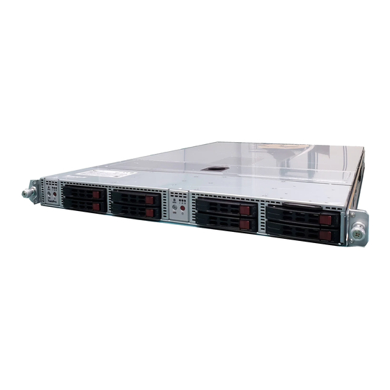
- Page 3 1U rackmount chassis and the X11DPT-PS dual processor serverboard. All models have an IPMI LAN port, two motherboard nodes and four (4) hot-swap 2.5" Hard Disk Drives (HDD) per node. Each of the various models of the TwinPro 1029TP-DTR/DC0R/DC1R servers have different backplanes as listed in the table below: TwinPro 1029TP-DTR/DC0R/DC1R...
- Page 4 Warnings Special attention should be given to the following symbols used in this manual. Warning! Indicates important information given to prevent equipment/property damage or personal injury. Warning! Indicates high voltage may be encountered when performing a procedure.
-
Page 5: Table Of Contents
Preface Contents Chapter 1 Introduction 1.1 Overview ..........................9 1.2 Unpacking the System ......................9 1.3 System Features ........................10 1.4 Server Chassis Features ....................11 Control Panel ........................11 Front Features ........................12 Rear Features ........................12 1.5 Motherboard Layout ......................13 Quick Reference Table ......................14 Chapter 2 Server Installation 2.1 Overview ..........................16 2.2 Preparing for Setup ......................16... - Page 6 TwinPro 1029TP-DTR/DC0R/DC1R User's Manual Chapter 3 Maintenance and Component Installation 3.1 Removing Power ........................24 3.2 Accessing the System ......................24 3.3 Motherboard Components ....................27 Processor and Heatsink Installation ..................27 The Xeon Series Processor ..................27 Assembling the Processor Package ................28 Removing the Dust Cover from the CPU Socket ............31 Installing the Processor Heatsink Module (PHM) ............32...
- Page 7 Preface Chapter 5 Software 5.1 OS Installation ........................62 Installing the Windows OS for a RAID System ..............62 Installing Windows to a Non-RAID System ..............62 5.2 Driver Installation ........................63 5.3 SuperDoctor 5 ........................64 ® 5.4 IPMI ............................65 Chapter 6 BIOS 6.1 Introduction .........................66 Starting the Setup Utility ....................66 6.2 Main Setup .........................67 6.3 Advanced Setup Configurations ..................68...
- Page 8 TwinPro 1029TP-DTR/DC0R/DC1R User's Manual Contacting Supermicro Headquarters Address: Super Micro Computer, Inc. 980 Rock Ave. San Jose, CA 95131 U.S.A. Tel: +1 (408) 503-8000 Fax: +1 (408) 503-8008 Email: marketing@supermicro.com (General Information) support@supermicro.com (Technical Support) Website: www.supermicro.com Europe Address: Super Micro Computer B.V.
-
Page 9: Overview
Chapter 1: Introduction Chapter 1 Introduction 1.1 Overview This chapter provides a brief outline of the functions and features of the 1029TP-DTR/DC0R/DC1R. The 1029TP-DTR/DC0R/DC1R is based on the X11DPT-PS motherboard and the SC809H-R1K05P3 chassis. In addition to the motherboard and chassis, several important parts that are included with the system are listed below. -
Page 10: System Features
TwinPro 1029TP-DTR/DC0R/DC1R User's Manual 1.3 System Features The following table provides you with an overview of the main features of the 1029TP-DTR/DC0R/DC1R. Please refer to Appendix C for additional specifications. System Features Motherboard X11DPT-PS Chassis SC809H-R1K05P3 Dual Intel® Xeon 81XX/61XX/51XX/41XX/31XX series processors; each processor supports UPI 10.4 GT/s Note: Both CPUs need to be installed for full access to the PCI-E slots, DIMM slots, and onboard controllers. -
Page 11: Server Chassis Features
Chapter 1: Introduction 1.4 Server Chassis Features Control Panel The switches and LEDs located on the control panel are described below. See Chapter 4 for details on the control panel connections. Figure 1-1. Control Panel View Control Panel Features Item Feature Description The main power button on each of the control panels is used to apply or remove power from the... -
Page 12: Front Features
TwinPro 1029TP-DTR/DC0R/DC1R User's Manual Front Features The SC809H-R1K05P3 is a mini 1U chassis See the illustration below for the features included on the front of the chassis. Figure 1-2. Chassis Front View Front Chassis Features Item Feature Description Control Panels (each Node) One control panel is provided on the chassis front for each node in the system. -
Page 13: Motherboard Layout
Chapter 1: Introduction 1.5 Motherboard Layout Below is a layout of the X11DPT-PS with jumper, connector and LED locations shown. See the table on the following page for descriptions. For detailed descriptions, pinout information and jumper settings, refer to Chapter 4. IPMI_LAN UID_LED1 JUIDB1... -
Page 14: Quick Reference Table
TwinPro 1029TP-DTR/DC0R/DC1R User's Manual Quick Reference Table Jumper Description Default Setting JBT1 CMOS Clear Open (Normal) (See Chpt. 3) JPME1 Manufacturing Mode Select Pins 1-2 (Normal) JWD1 Watch Dog Timer Enable Pins 1-2 (Reset) Connector Description Onboard CMOS battery COM1... - Page 15 Chapter 1: Introduction DIMMA2 DIMMJ1 DIMMA1 DIMMH1 DIMMB1 DIMMG1 DIMMC1 VCCP0 VCCP1 DIMMG2 VR13 VR13 DIMMD2 5+1 PHASE 5+1 PHASE DIMMM1 165W/205W UPI 10.4/1.2G 165W/205W DIMMD1 DIMML1 DIMME1 DIMMK1 DIMMF1 DIMMK2 CPU1 CPU2 #1 #3A PCI-E X16 PCI-E X8 PCI-E X16 PCI-E X16 PCI-E X16 PCI-E X8...
-
Page 16: Server Installation
TwinPro 1029TP-DTR/DC0R/DC1R User's Manual Chapter 2 Server Installation 2.1 Overview This chapter provides advice and instructions for mounting your system in a server rack. If your system is not already fully integrated with processors, system memory etc., refer to Chapter 4 for details on installing those specific components. -
Page 17: Server Precautions
Chapter 2: Server Installation • You should extend only one server or component at a time - extending two or more simul- taneously may cause the rack to become unstable. Server Precautions • Review the electrical and general safety precautions in Appendix B. •... -
Page 18: Reliable Ground
TwinPro 1029TP-DTR/DC0R/DC1R User's Manual Reliable Ground A reliable ground must be maintained at all times. To ensure this, the rack itself should be grounded. Particular attention should be given to power supply connections other than the direct connections to the branch circuit (i.e. the use of power strips, etc.). -
Page 19: Installing The System Into A Rack
Chapter 2: Server Installation 2.3 Installing the System into a Rack There are a variety of rack units on the market, which may require a slightly different assembly procedure. This rail set fits a rack between 25.6" and 33" deep. The following is a basic guideline for installing the system into a rack with the rack mounting hardware provided. -
Page 20: Assembling The Outer Rails
TwinPro 1029TP-DTR/DC0R/DC1R User's Manual Assembling the Outer Rails Each outer rail comes in two sections that must be assembled before mounting onto the rack. Assembling the Outer Rails 1. Identify the left and right outer rails by examining the ends, which bend outward. Match the left front outer rail with the left rear outer rail and the same for the right rails. -
Page 21: Installing The Outer Rails Onto The Rack
Chapter 2: Server Installation Installing the Outer Rails onto the Rack Each end of the assembled outer rail includes a bracket with square pegs to fit into your rack holes. If you have an older rack with round holes, these brackets must be removed, and you must use screws to secure the rail to the rack. -
Page 22: Sliding The Chassis Onto The Rack Rails
TwinPro 1029TP-DTR/DC0R/DC1R User's Manual Sliding the Chassis onto the Rack Rails Installing the Chassis into a Rack 1. Align the rear of the chassis rails with the front of the rack rails and then push evenly on both sides of the chassis. The spring latch engages when the chassis is part way in. -
Page 23: Installing The Server Into A Telco Rack
Chapter 2: Server Installation Installing the Server into a Telco Rack To install the server into a Telco (or “open”) type rack, use L-shaped brackets (p/n MCP-290- 00012-0N) on either side of the chassis (four total). Installing the Server into a Telco Rack 1. -
Page 24: Chapter 3 Maintenance And Component Installation
TwinPro 1029TP-DTR/DC0R/DC1R User's Manual Chapter 3 Maintenance and Component Installation This chapter provides instructions on installing and replacing main system components. To prevent compatibility issues, only use components that match the specifications and/or part numbers given. Installation or replacement of most components require that power first be removed from the system. - Page 25 Chapter 3: Maintenance and Component Installation Lock Figure 3-1. Unlocking the Cover Lock Latch Figure 3-2. Pulling the Cover Latch...
- Page 26 TwinPro 1029TP-DTR/DC0R/DC1R User's Manual Figure 3-3. Cover Open...
-
Page 27: Motherboard Components
Check that the plastic socket dust cover is in place and none of the socket pins are bent— otherwise, contact your retailer. • Refer to the Supermicro website for updates on CPU support. • Graphics in this manual are for illustration. Your components may look slightly different. -
Page 28: Assembling The Processor Package
TwinPro 1029TP-DTR/DC0R/DC1R User's Manual Assembling the Processor Package Attach the processor to the thin processor clip to create the processor package. 1. On the top corner of the CPU, locate pin 1 (A), marked by a triangle. Also, locate notch B and notch C (and notch D for F models) on the CPU as shown below. - Page 29 Chapter 3: Maintenance and Component Installation CPU (Upside Down) Align Notch D of the CPU w/CPU LGA Lands up and Notch D of the Processor Clip Align Notch C of the CPU Pin 1 and Notch C of the Processor Clip Align Notch B of the CPU and Notch B of the Processor Clip CPU/Heatsink Package...
- Page 30 TwinPro 1029TP-DTR/DC0R/DC1R User's Manual After creating the processor package assembly, mount it onto the heatsink to create the processor heatsink module (PHM). 1. On the heatsink label, locate "1" and the corner next to it. Turn the heatsink upside down with the thermal grease side facing up, keeping track of the "1" corner.
-
Page 31: Removing The Dust Cover From The Cpu Socket
Chapter 3: Maintenance and Component Installation Removing the Dust Cover from the CPU Socket Remove the dust cover from the CPU socket, exposing the socket pins as shown below. Caution: Do not touch the socket pins. Dust Cover Remove the dust cover from the CPU socket. -
Page 32: Installing The Processor Heatsink Module (Phm)
TwinPro 1029TP-DTR/DC0R/DC1R User's Manual Installing the Processor Heatsink Module (PHM) 1. Locate the triangle (pin 1) on the CPU socket. Also locate the pin 1 corner of the PHM that is closest to "1" on the heatsink label. To confirm, look at the underside of the PHM and note the hollow triangle in the processor clip and printed triangle on the CPU located next to a screw at the corner. -
Page 33: Removing The Processor Heatsink Module From The Motherboard
Chapter 3: Maintenance and Component Installation Removing the Processor Heatsink Module from the Motherboard Before removing the processor heatsink module (PHM), power down as described in Section 3.1. 1. Using a T30 Torx-bit screwdriver, loosen and remove the screws on the PHM from the socket, starting with the screw marked #4, in the sequence of 4, 3, 2, 1. -
Page 34: Memory Installation
2666 DRx4 16 GB 32 GB 2666 QRX4 2H-64GB 2666 RDIMM 3Ds 8RX4 4H-128GB 2666 LRDIMM QRx4 32 GB 64 GB 2666 QRX4 2H-64GB 2666 LRDIMM 8Rx4 4H-128 GB 2666 Check the Supermicro website for possible updates to memory support. -
Page 35: Memory Population Guidelines
Then, if using two DIMMs per channel, install the second DIMM in the black slot. The following memory population sequence table was created based on guidelines provided by Intel to support Supermicro motherboards. The diagram is for illustrative purposes; your motherboard may look different. - Page 36 TwinPro 1029TP-DTR/DC0R/DC1R User's Manual Memory Population for X11 DP Motherboard, 16 DIMM Slots When 1 CPU is used: Memory Population Sequence 1 CPU & 1 DIMM CPU1: P1-DIMMA1 1 CPU & 2 DIMMs CPU1: P1-DIMMA1/P1-DIMMD1 1 CPU & 3 DIMMs CPU1: P1-DIMMC1/P1-DIMMB1/P1-DIMMA1 1 CPU &...
- Page 37 Chapter 3: Maintenance and Component Installation CPU2 CPU1...
-
Page 38: Installing Memory
TwinPro 1029TP-DTR/DC0R/DC1R User's Manual Installing Memory ESD Precautions Electrostatic Discharge (ESD) can damage electronic com ponents including memory modules. To avoid damaging DIMM modules, it is important to handle them carefully. The following measures are generally sufficient. • Use a grounded wrist strap designed to prevent static discharge. -
Page 39: Memory Installation
(128-bit) memory, which is faster than non-interleaved (64-bit) memory. Check the Supermicro website for possible updates to memory support. Installing Memory Begin by removing power from the system as described in Section 3.1. -
Page 40: Dimm Removal
TwinPro 1029TP-DTR/DC0R/DC1R User's Manual Note: Visit the product page on the Supermicro website for possible updates to memory support (www.supermicro.com). DIMM Removal Reverse the steps above to remove the DIMM modules from the motherboard. PCI Expansion Card Installation The system includes a pre-installed riser card (p/n CSE-RR1U-E8) that positions a standard size PCI-E x8 card at a 90 degree angle, allowing it to fit inside the chassis. -
Page 41: Motherboard Battery
Chapter 3: Maintenance and Component Installation Motherboard Battery The motherboard uses non-volatile memory to retain system information when system power is removed. This memory is powered by a lithium battery residing on the motherboard. Replacing the Battery Begin by removing power from the system as described in section 3.1. 1. -
Page 42: Chassis Components
Release Button Figure 3-5. Removing a Hard Drive Note: Enterprise level hard disk drives are recommended for use in Supermicro chassis and servers. For information on recommended HDDs, visit the Supermicro website at http://www. - Page 43 Chapter 3: Maintenance and Component Installation Removing Hard Drive Carrier from the Chassis 1. Press the release button on the drive carrier. This extends the drive carrier handle. 2. Use the handle to pull the drive out of the chassis. 3.
- Page 44 TwinPro 1029TP-DTR/DC0R/DC1R User's Manual Installing a Drive into the Carrier 1. Remove the dummy drive from the carrier by removing four screws. 2. Install a new drive into the carrier with the printed circuit board side facing down so that the mounting holes in the drive align with those in the carrier.
-
Page 45: Air Shroud
Chapter 3: Maintenance and Component Installation Air Shroud The air shroud is used to concentrate airflow to maximize fan efficiency. The air shroud does not require screws to set up. Installing the Air Shroud 1. Lay the chassis on a flat, stable surface and remove the chassis cover. 1. -
Page 46: Installing An Adapter Card
TwinPro 1029TP-DTR/DC0R/DC1R User's Manual Installing an Adapter Card Adapter cards connect to the motherboard to the backplane and provide hot-swappable functionality to the node. Adapter Card Serverboard Drawer Figure 3-9. Adapter Card Installation Removing the Adapter Card 1. Remove the node from the back of the chassis. It is not necessary to power down the system. -
Page 47: Installing The Riser Card
Chapter 3: Maintenance and Component Installation Installing the Riser Card Installing the Riser Card 1. Use the control panel to power down the computing node, and pull the node drawer out of the chassis. 2. Remove the riser card bracket, removing the screw on the back of the drawer. 3. - Page 48 TwinPro 1029TP-DTR/DC0R/DC1R User's Manual Installing Expansion Cards 1. Use the control panel to power down the computing node, and pull the node drawer out of the chassis. 2. Open the PCI slot clip in the rear of the node drawer and remove the PCI slot shield.
-
Page 49: Siom Modules
Chapter 3: Maintenance and Component Installation SIOM Modules In addition, the 2028TP-HTR/HC0R/HC1R was designed to accept one of four different SIOM modules (Supermicro I/O Module) to satisfy the specific I/O functions required by the system. The various SIOM modules are as follows: •... - Page 50 TwinPro 1029TP-DTR/DC0R/DC1R User's Manual 5. Remove the two screws holding the SIOM module and carefully remove the module out of the chassis. 6. Replace with the new SIOM module desired and put the SIOM bracket back in place. Secure the bracket with its two screws (from step 5) using about 3-pounds of torgue and a slow speed (if using a power tool) or manually using a screwdriver.
-
Page 51: System Fans
Chapter 3: Maintenance and Component Installation System Fans Six hot-swappable fans provide cooling from the middle of the chassis. Replacing a System Fan 1. Use IPMI or another monitoring tool, if available, to determine which fan has failed. 2. Open the chassis cover. If a monitoring tool is not available, observe which fan has failed. -
Page 52: Power Supply
TwinPro 1029TP-DTR/DC0R/DC1R User's Manual Power Supply The chassis features redundant power supplies. They are hot-swappable, meaning they can be changed without powering down the system. New units can be ordered directly from Supermicro or authorized distributors. These power supplies are auto-switching capable. This feature enables them to automatically sense the input voltage and operate at a 100-120v or 180-240v. - Page 53 Chapter 3: Maintenance and Component Installation Changing the Power Supply: 1. Unplug the AC cord from the module to be replaced. 2. Push the release tab on the back of the power supply as illustrated. Release Tab Figure 3-16. Power Supply Release Tab 3.
-
Page 54: Chapter 4 Motherboard Connections
SuperServer 2029TP-HTR/HC1R/HC0R User's Manual Chapter 4 Motherboard Connections This section describes the connections on the motherboard and provides pinout definitions. Note that depending on how the system is configured, not all connections are required. The LEDs on the motherboard are also described here. A severboard layout indicating component locations may be found in Chapter 1. - Page 55 I-SATA0-3 are supported by CPU2 PCI-E 3.0 x16 slot on SXB2, and S-SATA0-5 are supported by the CPU1 PCI-E 3.0 x8 slot on SXB1. I-SATA4/ I-SATA5 can be used with Supermicro SuperDOMs, which are yellow SATA DOM connectors with power pins built in, and do not require external power cables.
-
Page 56: Ports
SuperServer 2029TP-HTR/HC1R/HC0R User's Manual 4.3 Ports See Figure 4-1 below for the locations and descriptions of the various I/O ports on the rear of the motherboard. IPMI_LAN UID_LED1 JUIDB1 COM1 BATTERY JSDCARD1 SIOM:CPU1 PCI-E 3.0 X16 JBT1 BMC SD CARD JSIOM1 HDD_LED SXB2... - Page 57 Chapter 4: Motherboard Connections VGA Port The onboard VGA port is located next to IPMI_LAN on the I/O back panel. Use this connection for VGA display. Serial Port A COM port (COM1) is located next to the VGA port on the motherboard. This COM port provides serial communication support.
- Page 58 Note: UID can also be triggered via IPMI on the motherboard. For more information on IPMI, please refer to the IPMI User's Guide posted on our website at http://www.supermicro.com. UID Switch...
-
Page 59: Jumpers
Chapter 4: Motherboard Connections 4.4 Jumpers Explanation of Jumpers To modify the operation of the motherboard, jumpers are used to choose between optional settings. Jumpers create shorts between two pins to change the function associated with it. Pin 1 is identified with a square solder pad on the printed circuit board. See the motherboard layout page for jumper locations. - Page 60 SuperServer 2029TP-HTR/HC1R/HC0R User's Manual Manufacturing Mode Select Close JPME1 to bypass SPI flash security and force the system to use the Manufacturing Mode, which will allow you to flash the system firmware from a host server to modify system settings. See the table below for jumper settings. Manufacturing Mode Select Jumper Settings Jumper Setting...
-
Page 61: Led Indicators
Chapter 4: Motherboard Connections 4.5 LED Indicators LAN LEDs Two LAN ports (LAN 1 and LAN 2) are located on the I/O back panel of the motherboard. Each Ethernet LAN port has two LEDs. The green LED indicates activity, while the other Link LED may be green, amber, or off to indicate the speed of the connection. -
Page 62: Chapter 5 Software
You must first configure RAID settings (if using RAID) before you install the Windows OS and the software drivers. To configure RAID settings, please refer to the RAID Configuration User Guides posted on our website at www.supermicro.com/support/manuals. Installing the Windows OS for a RAID System 1. -
Page 63: Driver Installation
Chapter 5: Software 5.2 Driver Installation The Supermicro FTP site contains drivers and utilities for your system at ftp://ftp.supermicro. com. Some of these must be installed, such as the chipset driver. After accessing the FTP site, go into the CDR_Images directory and locate the ISO file for your motherboard. -
Page 64: Superdoctor ® 5
5.3 SuperDoctor ® The Supermicro SuperDoctor 5 is a program that functions in a command-line or web-based interface for Windows and Linux operating systems. The program monitors such system health information as CPU temperature, system voltages, system power consumption, fan speed, and provides alerts via email or Simple Network Management Protocol (SNMP). -
Page 65: Ipmi
The X11DPT-PS support the Inteliigent Platform Management Interface (IPMI). IPMI is used to provide remote access, monitoring and management. There are several BIOS settings that are related to IPMI. For general documentation and information on IPMI, please visit our website at: http://www.supermicro.com/products/nfo/IPMI.cfm. -
Page 66: Chapter 6 Bios
TwinPro 1029TP-DTR/DC0R/DC1R User's Manual Chapter 6 BIOS 6.1 Introduction This chapter describes the AMIBIOS™ Setup utility for theX11DPT-PS X11DPT-PS motherboard. The BIOS is stored on a chip and can be easily upgraded using a flash program. Note: Due to periodic changes to the BIOS, some settings may have been added or deleted and might not yet be recorded in this manual. -
Page 67: Main Setup
Note: The time is in the 24-hour format. For example, 5:30 P.M. appears as 17:30:00. The date's default value is 01/01/2014 after RTC reset. Supermicro X11DPT-PS BIOS Version This item displays the version of the BIOS ROM used in the system. -
Page 68: Advanced Setup Configurations
TwinPro 1029TP-DTR/DC0R/DC1R User's Manual Build Date This item displays the date when the version of the BIOS ROM used in the system was built. CPLD Version This item displays the version of the CPLD (Complex-Programmable Logical Device) used in the system. - Page 69 Chapter 4: BIOS Warning: Take Caution when changing the Advanced settings. An incorrect value, an incorrect DRAM frequency, or an incorrect BIOS timing setting may cause the system to malfunction. When this occurs, restore the setting to the manufacture default setting. Boot Feature ...
- Page 70 TwinPro 1029TP-DTR/DC0R/DC1R User's Manual Port 61h Bit-4 Emulation Select Enabled for I/O Port 61h-Bit 4 emulation support to enhance system performance. The options are Enabled and Disabled. Power Configuration Watch Dog Function Select Enabled to allow the Watch Dog timer to reboot the system when it is inactive for more than 5 minutes.
- Page 71 Chapter 4: BIOS CPU Configuration Warning: Setting the wrong values in the following sections may cause the system to malfunc- tion. Processor Configuration The following CPU information will be displayed: • Processor BSP Revision • Processor Socket • Processor ID •...
- Page 72 TwinPro 1029TP-DTR/DC0R/DC1R User's Manual PPIN Control Select Unlock/Enable to use the Protected-Processor Inventory Number (PPIN) in the system. The options are Unlock/Enable and Unlock/Disable. Hardware Prefetcher (Available when supported by the CPU) If this feature is set to Enable, the hardware prefetcher will prefetch streams of data and instructions from the main memory to the Level 2 (L2) cache to improve CPU performance.
- Page 73 Chapter 4: BIOS Advanced Power Management Configuration CPU P State Control SpeedStep (PStates) EIST (Enhanced Intel SpeedStep Technology) allows the system to automatically adjust processor voltage and core frequency in an effort to reduce power consumption and heat dissipation.
- Page 74 TwinPro 1029TP-DTR/DC0R/DC1R User's Manual Enhanced Halt State (C1E) Select Enable to enable "Enhanced Halt State" support, which will significantly reduce the CPU's power consumption by minimizing CPU's clock cycles and reduce voltage during a "Halt State." The options are Disable and Enable.
- Page 75 Chapter 4: BIOS Degrade Precedence Use this feature to select the degrading precedence option for Ultra Path Interconnect connections. Select Topology Precedent to degrade UPI features if system options are in conflict. Select Feature Precedent to degrade UPI topology if system options are in conflict. The options are Topology Precedence and Feature Precedence.
- Page 76 TwinPro 1029TP-DTR/DC0R/DC1R User's Manual tCCD_L Relaxation If this feature is set to Enable, SPD (Serial Presence Detect) will override tCCD_L ("Column to Column Delay-Long", or “Command to Command Delay-Long” on the column side.) If this feature is set to Disable, tCCD_L will be enforced based on the memory frequency.
- Page 77 Chapter 4: BIOS Memory Rank Sparing Select Enable to support memory-rank sparing to optimize memory performance. The options are Enable and Disable. Note: This item will not be available when memory mirror mode is enabled. Correctable Error Threshold Use this item to enter the threshold value for correctable memory errors. The default setting is 10.
- Page 78 TwinPro 1029TP-DTR/DC0R/DC1R User's Manual IIO Configuration EV DFX (Device Function On-Hide) Features When this feature is set to Enable, the EV_DFX Lock Bits that are located in a processor will always remain clear during electric tuning. The options are Disable and Enable.
- Page 79 Chapter 4: BIOS IOAT Configuration Disable TPH (TLP Processing Hint) TPH is used for data-tagging with a destination ID and a few important attributes. It can send critical data to a particular cache without writing through to memory. Select No in this item for TLP Processing Hint support, which will allow a "TPL request"...
- Page 80 TwinPro 1029TP-DTR/DC0R/DC1R User's Manual Posted Interrupt Select Enable to support VT_D Posted Interrupt which will allow external interrupts to be sent directly from a direct-assigned device to a client machine in non-root mode to improve virtualization efficiency by simplifying interrupt migration and lessening the need of physical interrupts.
- Page 81 Chapter 4: BIOS Server ME (Management Engine) Configuration This feature displays the following system ME configuration settings. General ME Configuration Operational Firmware Version Backup Firmware Version Recovery Firmware Version ME Firmware Status #1/ME Firmware Status #2 Current State Error Code PCH SATA Configuration ...
- Page 82 TwinPro 1029TP-DTR/DC0R/DC1R User's Manual SATA RAID Option ROM/UEFI Driver (Available when the item "Configure SATA as" is set to "RAID") Select EFI to load the EFI driver for system boot. Select Legacy to load a legacy driver for system boot. The options are Disable, EFI, and Legacy.
- Page 83 Chapter 4: BIOS Support Aggressive Link Power Management When this item is set to Enable, the sSATA AHCI controller manages the power use of the SATA link. The controller will put the link in a low power mode during an extended period of I/O inactivity, and will return the link to an active state when I/O activity resumes.
- Page 84 TwinPro 1029TP-DTR/DC0R/DC1R User's Manual MMIO High Base Use this feature to select the base memory size according to memory-address mapping for the IO hub. The base memory size must be between 4032G to 4078G. The options are 56T, 40T, 24T, 16T, 4T, and 1T.
- Page 85 Chapter 4: BIOS Network Stack Configuration Network Stack Select Enabled to enable PXE (Preboot Execution Environment) or UEFI (Unified Extensible Firmware Interface) for network stack support. The options are Enabled and Disabled. *If "Network Stack" is set to Enabled, the following items will display: Ipv4 PXE Support Select Enabled to enable Ipv4 PXE boot support.
- Page 86 TwinPro 1029TP-DTR/DC0R/DC1R User's Manual Device Settings This feature displays the base I/O port address and the Interrupt Request address of a serial port specified by the user. Note: This item is hidden when Serial Port 1 is set to Disabled.
- Page 87 Chapter 4: BIOS Serial Port Console Redirection COM 1 Console Redirection Select Enabled to enable COM Port 1 for Console Redirection, which will allow a client machine to be connected to a host machine at a remote site for networking. The options are Enabled and Disabled.
- Page 88 TwinPro 1029TP-DTR/DC0R/DC1R User's Manual Flow Control Use this feature to set the flow control for Console Redirection to prevent data loss caused by buffer overflow. Send a "Stop" signal to stop sending data when the receiving buffer is full. Send a "Start" signal to start sending data when the receiving buffer is empty. The options are None and Hardware RTS/CTS.
- Page 89 Chapter 4: BIOS Console Redirection Settings (for SOL/COM2) Use this feature to specify how the host computer will exchange data with the client computer, which is the remote computer used by the user. Terminal Type Use this feature to select the target terminal emulation type for Console Redirection. Select VT100 to use the ASCII Character set.
- Page 90 TwinPro 1029TP-DTR/DC0R/DC1R User's Manual Recorder Mode Select Enabled to capture the data displayed on a terminal and send it as text messages to a remote server. The options are Disabled and Enabled. Resolution 100x31 Select Enabled for extended-terminal resolution support. The options are Disabled and Enabled.
- Page 91 Chapter 4: BIOS EMS Console Redirection Settings Out-of-Band Management Port The feature selects a serial port in a client server to be used by the Windows Emergency Management Services (EMS) to communicate with a remote host server. The options are COM1 (Console Redirection) and COM2/SOL (Console Redirection).
- Page 92 TwinPro 1029TP-DTR/DC0R/DC1R User's Manual WHEA Support Select Enabled to support the Windows Hardware Error Architecture (WHEA) platform and provide a common infrastructure for the system to handle hardware errors within the Windows OS environment to reduce system crashes and to enhance system recovery and health monitoring.
- Page 93 Chapter 4: BIOS Platform Hierarchy (for TPM Version 2.0 and above) Select Enabled for TPM Platform Hierarchy support which will allow the manufacturer to utilize the cryptographic algorithm to define a constant key or a fixed set of keys to be used for initial system boot.
- Page 94 TwinPro 1029TP-DTR/DC0R/DC1R User's Manual PH (Platform Hierarchy) Randomization (for TPM Version 2.0 and above) Select Enabled for Platform Hierarchy Randomization support, which is used only during the platform developmental stage. This feature cannot be enabled in the production platforms. The options are Disabled and Enabled.
-
Page 95: Event Logs
Chapter 4: BIOS 6.3 Event Logs Use this feature to configure Event Log settings. Change SMBIOS Event Log Settings Enabling/Disabling Options SMBIOS Event Log Select Enabled to enable SMBIOS (System Management BIOS) Event Logging during system boot. The options are Enabled and Disabled. Erasing Settings Erase Event Log Select Enabled to erase all error events in the SMBIOS (System Management BIOS) log... - Page 96 TwinPro 1029TP-DTR/DC0R/DC1R User's Manual When Log is Full Select Erase Immediately to immediately erase all errors in the SMBIOS event log when the event log is full. Select Do Nothing for the system to do nothing when the SMBIOS event log is full.
-
Page 97: Ipmi
Chapter 4: BIOS 6.4 IPMI Use this feature to configure Intelligent Platform Management Interface (IPMI) settings. When you select this submenu and press the <Enter> key, the following information will display: • BMC Firmware Revision: This feature indicates the IPMI firmware revision used in your system. - Page 98 TwinPro 1029TP-DTR/DC0R/DC1R User's Manual Erase SEL Select Yes, On next reset to erase all system event logs upon next system reboot. Select Yes, On every reset to erase all system event logs upon each system reboot. Select No to keep all system event logs after each system reboot. The options are No, Yes, On next reset, and Yes, On every reset.
- Page 99 Chapter 4: BIOS • Gateway IP Address: This feature displays the Gateway IP address for this computer. This should be in decimal and in dotted quad form (i.e., 192.168.10.253). • VLAN: Select Enabled to enable IPMI VLAN support. The options are Enabled and Dis- abled.
-
Page 100: Security Settings
TwinPro 1029TP-DTR/DC0R/DC1R User's Manual 6.5 Security Settings This menu allows the user to configure the following security settings for the system. Administrator Password Use this feature to set the administrator password which is required to enter the BIOS setup utility. The length of the password should be from 3 characters to 20 characters long. - Page 101 Chapter 4: BIOS Secure Boot When you select this submenu and press the <Enter> key, the following items will display: • System Mode • Secure Boot • Vendor Keys Secure Boot If this feature is set to Enabled, Secure Boot will be activated when a Platform Key (PK) is entered.
- Page 102 TwinPro 1029TP-DTR/DC0R/DC1R User's Manual Platform Key (PK) This feature allows the user to enter and configure a set of values to be used as a platform firmware key for the system. This set of values also indicate the size, the keys numbers, and the key source of the Platform Key.
-
Page 103: Boot Settings
Chapter 4: BIOS 6.6 Boot Settings Use this feature to configure Boot Settings: Boot Mode Select Use this feature to select the type of devices to be used for system boot. The options are Legacy, UEFI (Unified Extensible Firmware Interface), and Dual. Legacy to EFI Support Select Enabled for the system to boot from an EFI OS when the Legacy OS fails. - Page 104 TwinPro 1029TP-DTR/DC0R/DC1R User's Manual When the item above -"Boot Mode Select" is set to Legacy, the following items will be display for configuration: • Boot Option #1 - Boot Option #7 When the item above -"Boot Mode Select" is set to UEFI, the following items will be display for configuration: •...
- Page 105 Chapter 4: BIOS Create After the driver option name and the file path are set, press <Enter> to enter to submenu and click OK to create the new boot option drive. Delete Driver Option Use this item to select a boot driver to delete from the boot priority list. Delete Drive Option Select the target boot driver to delete from the boot priority list.
-
Page 106: Save & Exit
TwinPro 1029TP-DTR/DC0R/DC1R User's Manual 6.7 Save & Exit Select the Save & Exit tab from the BIOS setup screen to configure the settings below. Save Options Discard Changes and Exit Select this option to quit the BIOS setup without making any permanent changes to the system configuration and reboot the computer. - Page 107 Chapter 4: BIOS Discard Changes Select this option and press <Enter> to discard all the changes and return to the AMI BIOS setup utility. Default Options Restore Optimized Defaults To set this feature, select Restore Defaults from the Exit menu and press <Enter> to load manufacturer default settings which are intended for maximum system performance but not for maximum stability.
-
Page 108: Appendix A Bios Codes
TwinPro 1029TP-DTR/DC0R/DC1R User's Manual Appendix A BIOS Codes A.1 BIOS Error POST (Beep) Codes During the POST (Power-On Self-Test) routines, which are performed each time the system is powered on, errors may occur. Non-fatal errors are those which, in most cases, allow the system to continue the boot-up process. - Page 109 When BIOS performs the Power On Self Test, it writes checkpoint codes to I/O port 0080h. If the computer cannot complete the boot process, a diagnostic card can be attached to the computer to read I/O port 0080h (Supermicro p/n AOC-LPC80-20). For information on AMI updates, please refer to http://www.ami.com/products/.
-
Page 110: Appendix B Standardized Warning Statements For Ac Systems
Supermicro's Technical Support department for assistance. Only certified technicians should attempt to install or configure components. Read this appendix in its entirety before installing or configuring components in the Supermicro chassis. These warnings may also be found on our website at http://www.supermicro.com/about/... - Page 111 Appendix B: Standardized Warning Statements Warnung WICHTIGE SICHERHEITSHINWEISE Dieses Warnsymbol bedeutet Gefahr. Sie befinden sich in einer Situation, die zu Verletzungen führen kann. Machen Sie sich vor der Arbeit mit Geräten mit den Gefahren elektrischer Schaltungen und den üblichen Verfahren zur Vorbeugung vor Unfällen vertraut. Suchen Sie mit der am Ende jeder Warnung angegebenen Anweisungsnummer nach der jeweiligen Übersetzung in den übersetzten Sicherheitshinweisen, die zusammen mit diesem Gerät ausgeliefert wurden.
- Page 112 SuperServer 1029TP-DTR/DC0R/DC1R User's Manual . ٌ ا ك ً ف حالة و ٌ يك أى تتسبب ف اصابة جسذ ة ٌ هذا الزهز ع ٌ خطز !تحذ ز قبل أى تعول عىل أي هعذات،يك عىل علن بالوخاطز ال ا ٌجوة عي الذوائز ٍ...
- Page 113 Appendix B: Standardized Warning Statements Warnung Vor dem Anschließen des Systems an die Stromquelle die Installationsanweisungen lesen. ¡Advertencia! Lea las instrucciones de instalación antes de conectar el sistema a la red de alimentación. Attention Avant de brancher le système sur la source d'alimentation, consulter les directives d'installation. .יש...
- Page 114 SuperServer 1029TP-DTR/DC0R/DC1R User's Manual Warnung Dieses Produkt ist darauf angewiesen, dass im Gebäude ein Kurzschluss- bzw. Überstromschutz installiert ist. Stellen Sie sicher, dass der Nennwert der Schutzvorrichtung nicht mehr als: 250 V, 20 A beträgt. ¡Advertencia! Este equipo utiliza el sistema de protección contra cortocircuitos (o sobrecorrientes) del edificio.
- Page 115 Appendix B: Standardized Warning Statements Power Disconnection Warning Warning! The system must be disconnected from all sources of power and the power cord removed from the power supply module(s) before accessing the chassis interior to install or remove system components. 電源切断の警告...
- Page 116 SuperServer 1029TP-DTR/DC0R/DC1R User's Manual يجب فصم اننظاو من جميع مصادر انطاقت وإ ز انت سهك انكهرباء من وحدة امداد انطاقت قبم انىصىل إىن امنناطق انداخهيت نههيكم نتثبيج أو إ ز انت مكىناث الجهاز 경고! 시스템에 부품들을 장착하거나 제거하기 위해서는 섀시 내부에 접근하기 전에 반드시 전원 공급장치로부터...
- Page 117 Appendix B: Standardized Warning Statements Attention Il est vivement recommandé de confier l'installation, le remplacement et la maintenance de ces équipements à des personnels qualifiés et expérimentés. !אזהרה .צוות מוסמך בלבד רשאי להתקין, להחליף את הציוד או לתת שירות עבור הציוד واملدربيه...
- Page 118 SuperServer 1029TP-DTR/DC0R/DC1R User's Manual Warnung Diese Einheit ist zur Installation in Bereichen mit beschränktem Zutritt vorgesehen. Der Zutritt zu derartigen Bereichen ist nur mit einem Spezialwerkzeug, Schloss und Schlüssel oder einer sonstigen Sicherheitsvorkehrung möglich. ¡Advertencia! Esta unidad ha sido diseñada para instalación en áreas de acceso restringido. Sólo puede obtenerse acceso a una de estas áreas mediante la utilización de una herramienta especial, cerradura con llave u otro medio de seguridad.
- Page 119 Appendix B: Standardized Warning Statements Battery Handling Warning! There is the danger of explosion if the battery is replaced incorrectly. Replace the battery only with the same or equivalent type recommended by the manufacturer. Dispose of used batteries according to the manufacturer's instructions 電池の取り扱い...
- Page 120 SuperServer 1029TP-DTR/DC0R/DC1R User's Manual هناك خطر من انفجار يف حالة اسحبذال البطارية بطريقة غري صحيحة فعليل اسحبذال البطارية فقط بنفس النىع أو ما يعادلها مام أوصث به الرشمة املصنعة جخلص من البطاريات املسحعملة وفقا لحعليامت الرشمة الصانعة 경고! 배터리가 올바르게 교체되지 않으면 폭발의 위험이 있습니다. 기존 배터리와 동일하거나 제 조사에서...
- Page 121 Appendix B: Standardized Warning Statements ¡Advertencia! Puede que esta unidad tenga más de una conexión para fuentes de alimentación. Para cortar por completo el suministro de energía, deben desconectarse todas las conexiones. Attention Cette unité peut avoir plus d'une connexion d'alimentation. Pour supprimer toute tension et tout courant électrique de l'unité, toutes les connexions d'alimentation doivent être débranchées.
- Page 122 SuperServer 1029TP-DTR/DC0R/DC1R User's Manual Backplane Voltage Warning! Hazardous voltage or energy is present on the backplane when the system is operating. Use caution when servicing. バックプレーンの電圧 システムの稼働中は危険な電圧または電力が、 バックプレーン上にかかっています。 修理する際には注意く ださい。 警告 当系统正在进行时,背板上有很危险的电压或能量,进行维修时务必小心。 警告 當系統正在進行時,背板上有危險的電壓或能量,進行維修時務必小心。 Warnung Wenn das System in Betrieb ist, treten auf der Rückwandplatine gefährliche Spannungen oder Energien auf.
- Page 123 Appendix B: Standardized Warning Statements هناك خطز مه التيار الكهزبايئ أوالطاقة املىجىدة عىل اللىحة عندما يكىن النظام يعمل كه حذ ر ا عند خدمة هذا الجهاس 경고! 시스템이 동작 중일 때 후면판 (Backplane)에는 위험한 전압이나 에너지가 발생 합니다. 서비스 작업 시 주의하십시오. Waarschuwing Een gevaarlijke spanning of energie is aanwezig op de backplane wanneer het systeem in gebruik is.
- Page 124 SuperServer 1029TP-DTR/DC0R/DC1R User's Manual תיאום חוקי החשמל הארצי !אזהרה .התקנת הציוד חייבת להיות תואמת לחוקי החשמל המקומיים והארציים تركيب املعدات الكهربائية يجب أن ميتثل للقىاويه املحلية والىطىية املتعلقة بالكهرباء 경고! 현 지역 및 국가의 전기 규정에 따라 장비를 설치해야 합니다. Waarschuwing Bij installatie van de apparatuur moet worden voldaan aan de lokale en nationale elektriciteitsvoorschriften.
- Page 125 Appendix B: Standardized Warning Statements Attention La mise au rebut ou le recyclage de ce produit sont généralement soumis à des lois et/ou directives de respect de l'environnement. Renseignez-vous auprès de l'organisme compétent. סילוק המוצר !אזהרה .סילוק סופי של מוצר זה חייב להיות בהתאם להנחיות וחוקי המדינה التخلص...
- Page 126 SuperServer 1029TP-DTR/DC0R/DC1R User's Manual Warnung Gefährlich Bewegende Teile. Von den bewegenden Lüfterblätter fern halten. Die Lüfter drehen sich u. U. noch, wenn die Lüfterbaugruppe aus dem Chassis genommen wird. Halten Sie Finger, Schraubendreher und andere Gegenstände von den Öffnungen des Lüftergehäuses entfernt.
- Page 127 Verbindungskabeln, Stromkabeln und/oder Adapater, die Ihre örtlichen Sicherheitsstandards einhalten. Der Gebrauch von anderen Kabeln und Adapter können Fehlfunktionen oder Feuer verursachen. Die Richtlinien untersagen das Nutzen von UL oder CAS zertifizierten Kabeln (mit UL/CSA gekennzeichnet), an Geräten oder Produkten die nicht mit Supermicro gekennzeichnet sind.
- Page 128 .قيرح وأ لطع يف ببستي دق ىرخأ تالوحمو تالباك يأ مادختسا .ميلسلا سباقلاو لصوملا مجح لبق نم ةدمتعملا تالباكلا مادختسا تادعملاو ةيئابرهكلا ةزهجألل ةمالسلا نوناق رظحيUL وأCSA ( ةمالع لمحت يتلاوUL/CSA) لبق نم ةددحملاو ةينعملا تاجتنملا ريغ ىرخأ تادعم يأ عمSupermicro.
- Page 129 사항을 준수하여 제공되거나 지정된 연결 혹은 구매 케이블, 전원 케이블 및 AC 어댑터를 사용하십시오. 다른 케이블이나 어댑터를 사용하면 오작동이나 화재가 발생할 수 있습니다. 전기 용품 안전법은 UL 또는 CSA 인증 케이블 (코드에 UL / CSA가 표시된 케이블)을 Supermicro 가 지정한 제품 이외의 전기 장치에 사용하는 것을 금지합니다. Stroomkabel en AC-Adapter...
-
Page 130: Appendix C System Specifications
Integrated memory controller supports up to 2 TB of LRDIMM/RDIMM/NVDIMM DDR4 (288-pin) ECC 2666/2400/2133/1866/1600/1333 MHz modules in sixteen (16) slots at up to 128GB at 1.2V. Note: For the latest CPU/memory updates, please refer to our website at http://www.supermicro.com/products/motherboard. SATA Controller... - Page 131 Appendix C: System Specifications Regulatory Compliance Electromagnetic Emissions: FCC Class A, EN 55032 Class A, EN 61000-3-2/3-3, CISPR 32 Class A Electromagnetic Immunity: EN 55024/CISPR 24, (EN 61000-4-2, EN 61000-4-3, EN 61000-4-4, EN 61000-4-5, EN 61000-4-6, EN 61000-4-8, EN 61000-4-11) Other: VCCI-CISPR 32 and AS/NZS CISPR 32 Environmental: Directive 2011/65/EU and Directive 2012/19/EU Safety: CSA/EN/IEC/UL 60950-1 Compliant, UL or CSA Listed (USA and Canada), CE Marking (Europe)
-
Page 132: Appendix D Uefi Bios Recovery
Warning: Do not upgrade the BIOS unless your system has a BIOS-related issue. Flashing the wrong BIOS can cause irreparable damage to the system. In no event shall Supermicro be liable for direct, indirect, special, incidental, or consequential damages arising from a BIOS update. - Page 133 USB device or a writable CD/DVD. Note: If you cannot locate the "Super.ROM" file in your driver disk, visit our website at www. supermicro.com to download the BIOS image into a USB flash device and rename it "Super. ROM" for BIOS recovery use.
- Page 134 TwinPro 1029TP-DTR/DC0R/DC1R User's Manual Warning: Please stop pressing the <Ctrl> and <Home> keys immediately when you see the screen (or a similar screen) below; otherwise, it will trigger a system reboot. 4. After locating the new BIOS binary image, the system will enter the BIOS Recovery menu as shown below.
- Page 135 Appendix D: UEFI BIOS Recovery 5. When the screen as shown above displays, use the arrow keys to select the item "Proceed with flash update" and press the <Enter> key. You will see the BIOS recovery progress as shown in the screen below. Note: Do not interrupt the BIOS flashing process until it has completed.
- Page 136 TwinPro 1029TP-DTR/DC0R/DC1R User's Manual 8. Press <Del> continuously during system boot to enter the BIOS setup utility. From the top of the tool bar, click on Boot and press <Enter> to enter the submenu. From the submenu list, select Boot Option #1 as shown below. Then, boot Option #1 to [UEFI AP:UEFI: Built-in EFI Shell].
Need help?
Do you have a question about the TwinPro 1029TP-DTR and is the answer not in the manual?
Questions and answers