
Related Manuals for Supermicro SuperServer 1029GQ-TVRT


Summarization of Contents
Preface
About this Manual
Describes the manual's purpose and target audience.
Notes
Provides links to download necessary drivers, utilities, and manuals.
Warnings
Explains warning symbols used in the manual.
Contacting Supermicro
Headquarters
Provides contact information for Supermicro's headquarters.
Europe
Provides contact information for Supermicro's European branch.
Asia-Pacific
Provides contact information for Supermicro's Asia-Pacific branch.
Chapter 1 Introduction
1.1 Overview
Provides a brief outline of server models and their features.
1.2 Unpacking the System
Instructions for unpacking the server and choosing a setup location.
1.3 System Features
An overview of the main features of the SuperServer.
1.4 Server Chassis Features
Details on the features of the server chassis.
Control Panel
Description of control panel LEDs and buttons.
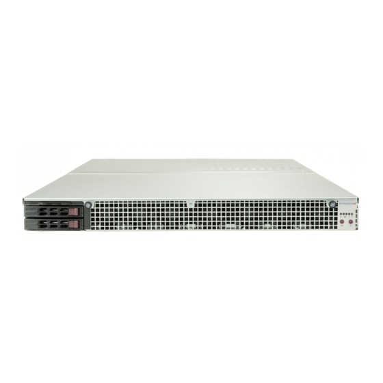
Front Features
Description of features located on the front of the chassis.
Rear Features
Description of features located on the rear of the chassis.
1.5 GPU Configurations
Information on GPU support for different server models.
1029GQ-TRT/1029GQ-TNRT: PCI Version
GPU configuration details for TRT and TNRT models.
1029GQ-TXRT: Add-on Module Version
GPU configuration details for the TXRT model with add-on module.
1029GQ-TVRT: Add-on Module Version
GPU configuration details for the TVRT model with add-on module.
1.6 Motherboard Layout
Diagram showing the layout of motherboard components.
Quick Reference
Summary of jumpers, connectors, and LEDs for quick reference.
System Block Diagram
A block diagram illustrating the system architecture.
Chapter 2 Server Installation
2.1 Overview
Introduction to the server installation chapter.
2.2 Preparing for Setup
Steps and precautions before installing the server.
Choosing a Setup Location
Guidance on selecting an appropriate location for the server.
Rack Precautions
Safety precautions specifically for rack installations.
Server Precautions
General safety precautions for server installation.
Rack Mounting Considerations
Factors to consider when mounting the server in a rack.
Ambient Operating Temperature
Requirements for ambient operating temperature.
Airflow
Considerations for proper airflow within the rack.
Mechanical Loading
Guidelines for mechanical loading in rack installations.
Circuit Overloading
Considerations regarding circuit overloading and power supply.
Reliable Ground
Importance and procedure for maintaining a reliable ground.
2.3 Installing the Rails
Instructions for installing the rack rails.
Identifying the Sections of the Rack Rails
Identifying the components of the rack rail kit.
Releasing the Inner Rail
Steps to release the inner rail from the middle and outer rails.
Releasing the Inner Rail from the Middle and Outer Rails
Detailed steps for separating inner rail components.
Installing The Inner Rails on the Chassis
Procedure for attaching the inner rails to the server chassis.
Installing the Inner Rails
Step-by-step guide for inner rail installation.
Installing the Outer Rails on the Rack
Procedure for attaching the outer rails to the server rack.
Installing the Outer Rails
Step-by-step guide for outer rail installation.
2.4 Installing into the Rack
Instructions for inserting the server chassis into the installed rack rails.
Installing the Chassis into a Rack
Step-by-step guide for mounting the chassis into the rack.
Removing the Chassis From the Rack
Procedure for removing the server chassis from the rack.
Chapter 3 Maintenance and Component Installation
3.1 Removing Power
Procedure to safely remove power from the system.
3.2 Accessing the System
Instructions on how to access the internal components of the system.
Removing the Top Cover
Steps to remove the chassis top cover for access.
3.3 Motherboard Components
Details and installation procedures for motherboard components.
Processor and Heatsink Installation
Procedure for installing the processor and heatsink module.
The Processor
Information about the supported Intel Xeon processor types.
The Processor Carrier Assembly
Description of the processor and its carrier assembly.
Overview of the Processor Heatsink Module
Description of the Processor Heatsink Module (PHM).
Creating the Processor Carrier Assembly
Steps to assemble the processor and its carrier.
Assembling the Processor Heatsink Module
Steps to assemble the processor carrier with the heatsink.
Preparing the CPU Socket for Installation
Procedure to prepare the CPU socket before installing the processor.
Installing the Processor Heatsink Module
Steps to install the assembled Processor Heatsink Module.
Memory
Information regarding memory support and installation.
Memory Support
Details on supported memory types, speeds, and capacities.
Memory Population Guidelines
Rules and recommendations for populating memory slots.
Guidelines Regarding Mixing DIMMs
Rules for mixing different types of DIMM modules.
DIMM Construction
Information on different DIMM construction types.
Memory Population Sequence
Sequence for installing memory modules in slots.
Memory Population for X11 DP Motherboard, 12 DIMM Slots
Memory population tables for 12 DIMM slots with 1 or 2 CPUs.
DCPMM Population for 2nd Gen Scalable Processors (82xx/62xx/52xx/42xx)
Guide for DCPMM population with 2nd Gen Scalable Processors.
Symmetric Population within one CPU
Symmetric population modes for CPUs.
Installing Memory
Step-by-step instructions for installing memory modules.
ESD Precautions
Electrostatic Discharge precautions for handling memory modules.
Removing Memory
Procedure for removing memory modules.
Motherboard Battery
Information about the motherboard's lithium battery.
Replacing the Battery
Instructions for replacing the motherboard battery.
3.4 Chassis Components
Details on various chassis components.
Storage Drives
Information regarding storage drive bays and installation.
Externally Accessible Drives
Details on hot-swap drive bays and carriers.
Removing a Hot-Swap Drive Carrier
Steps to remove a hot-swap drive carrier.
Mounting a Drive in a Drive Carrier
Steps to mount a hard drive into a carrier.
Internal Drives
Information on the system's internal fixed hard disk drives.
Installing Internal Drives
Steps for installing internal hard disk drives.
Graphics Processing Units
Information about supported Graphics Processing Units (GPUs).
GPUs in 1029GQ-TXRT and 1029GQ-TVRT
GPU support details for TXRT and TVRT models.
Installing GPUs on an Add-on Module
Steps for installing GPUs onto an add-on module.
GPUs in 1029GQ-TRT and 1029GQ-TNRT
GPU support details for TRT and TNRT models.
Installing the Front GPUs
Steps for installing front GPUs using the riser card.
Installing the Rear GPU
Steps for installing rear GPUs using the riser card.
System Cooling
Information about the system's cooling fans and airflow.
Installing Fans
Steps for installing or replacing system fans.
Air Shroud and Block
Details on the air shroud and block for cooling.
Installing the Air Shroud
Steps to install the air shroud into the chassis.
Power Supply
Information regarding the system's redundant power supplies.
Power Supply LEDs
Description of the status LEDs on the power supply modules.
Changing the Power Supply Module
Procedure for replacing a power supply module.
Chapter 4 Motherboard Connections
4.1 Power Connections
Details on how to connect power to the motherboard.
Main ATX Power
Information about the main ATX power connection.
GPU Power Headers
Details on the GPU power connection headers.
4.2 Headers and Connectors
Details on various motherboard headers and connectors.
Fan Headers
Details and pin definitions for fan headers.
TPM Header
Details and pin definitions for the TPM header.
Intel RAID Key Header
Details and pin definitions for the Intel RAID Key header.
SGPIO Headers
Details and pin definitions for SGPIO headers.
Standby Power
Details and pin definitions for the standby power header.
Chassis Intrusion
Details and pin definitions for the chassis intrusion header.
M.2 Slot
Information about the M.2 slot for storage devices.
Micro SD Card
Information about the Micro SD card slot.
Control Panel
Details on control panel connections and pin assignments.
Power Button
Details on the power button connection and function.
Reset Button
Details on the reset button connection.
Power Fail LED
Details on the power fail LED connection.
Fan Fail and UID LED
Details on fan fail and UID LED connections.
LAN1/LAN2 LED
Details on LAN activity and link LEDs.
HDD LED
Details on the HDD activity LED connection.
Power LED
Details on the power LED connection.
NMI Button
Details on the NMI button header.
4.3 Ports
Details on the system's various ports.
Ethernet Ports
Details on Ethernet ports including IPMI LAN.
SATA Ports
Information about the system's SATA ports.
Universal Serial Bus (USB) Ports
Details on the system's USB ports.
4.4 Jumpers
Details on motherboard jumpers and their functions.
Explanation of Jumpers
General explanation of how jumpers modify motherboard settings.
CMOS Clear
Information about the CMOS clear jumper (JBT1).
To Clear CMOS
Step-by-step instructions for clearing the CMOS.
Manufacturing Mode Select
Information on the manufacturing mode select jumper.
Watch Dog
Information on the Watch Dog timer jumper.
4.5 LED Indicators
Detailed description of system LEDs and their meanings.
Ethernet Ports
Details on Ethernet port LEDs (Activity and Link).
IPMI LAN Port
Details on IPMI LAN port LEDs.
BMC Heartbeat LED
Description of the BMC heartbeat LED.
Onboard Power LED
Description of the onboard power LED.
Unit ID LED
Description of the unit ID LED on the back panel.
Chapter 5 Software
5.1 Microsoft Windows OS Installation
Instructions for installing the Microsoft Windows Operating System.
Installing the OS
Step-by-step guide for installing the operating system.
5.2 Driver Installation
Instructions for installing system drivers and utilities.
5.3 SuperDoctor® 5
Information about the SuperDoctor 5 system monitoring software.
5.4 IPMI
Information about the Intelligent Platform Management Interface (IPMI).
Chapter 6 BIOS
6.1 Introduction
Introduction to the BIOS setup utility.
Starting BIOS Setup Utility
How to enter the BIOS setup utility.
6.2 Main Setup
Description of the main BIOS setup screen.
The Main tab page
Details on the Main tab in the BIOS setup utility.
System Date/System Time
Instructions for setting the system date and time.
6.3 Advanced Setup Configurations
Overview of advanced BIOS setup configurations.
Boot Feature
Settings related to the system's boot features.
Quiet Boot
Setting to control boot messages display.
Option ROM Messages
Setting to control Option ROM display mode.
Bootup NumLock State
Setting for the NumLock key state on power-on.
Wait For "F1" If Error
Setting to wait for F1 key press on error.
INT19 (Interrupt 19) Capture
Setting for capturing Interrupt 19 for boot disk function.
Re-try Boot
Setting to automatically reboot from a specified device after boot failure.
Power Configuration
Settings related to system power management.
Watch Dog Function
Setting to enable or disable the Watch Dog Timer.
Power Button Function
Controls how the system shuts down when the power button is pressed.
Restore on AC Power Loss
Setting for system power state after AC power loss.
CPU Configuration
Settings related to CPU configuration.
Processor Configuration
Details on processor configuration information displayed.
Hyper-Threading (ALL)
Setting to enable Intel Hyper-Threading Technology.
Execute Disable Bit
Setting to enable Execute-Disable Bit for security.
Intel Virtualization Technology
Setting to enable Intel Virtualization Technology (Vanderpool).
PPIN Control
Setting to control Protected-Processor Inventory Number (PPIN).
Hardware Prefetcher
Setting to enable hardware prefetcher for CPU performance.
Adjacent Cache Prefetch
Setting to control adjacent cache prefetch behavior.
DCU Streamer Prefetcher
Setting for DCU Streamer Prefetcher.
DCU IP Prefetcher
Setting for DCU IP Prefetcher.
LLC Prefetch
Setting to enable hardware prefetcher for L3 cache.
Extended APIC
Setting to enable Advanced Programmable Interrupt Controller support.
AES-NI
Setting to enable Intel Advanced Encryption Standard instructions.
Advanced Power Management Configuration
Settings for advanced power management configurations.
CPU P State Control
Settings for controlling CPU P-state.
Speedstep (Pstates)
Setting for Intel SpeedStep Technology.
EIST PSD Funtion
Setting for Enhanced Intel SpeedStep Technology function.
Turbo Mode
Setting to enable dynamic processor frequency control.
Hardware PM State Control
Settings for hardware power management state control.
Hardware P-States
Settings for hardware P-state selection.
CPU C State Control
Settings for CPU C-state control.
Autonomous Core C-State
Setting to enable autonomous core C-state control.
CPU C6 Report
Setting to allow BIOS to report CPU C6 State.
Enhanced Halt State (C1E)
Setting for Enhanced Halt State technology.
Package C State Control
Settings for package C-state control.
Chipset Configuration
Settings for chipset configuration.
North Bridge
Settings for North Bridge configuration.
UPI Configuration
Settings for UPI configuration.
UPI General Configuration
General settings for UPI configuration.
Degrade Precedence
Setting for degrade precedence when system settings conflict.
Link L0p Enable
Setting to enable Link L0p support.
Link L1 Enable
Setting to enable Link L1 support.
IO Directory Cache (IODC)
Setting for IO Directory Cache.
Isoc Mode
Setting for Isochronous support (QoS).
Memory Configuration
Settings for memory configuration.
Enforce POR
Setting to enforce POR restrictions on DDR4 frequency and voltage.
Memory Frequency
Setting for maximum memory frequency.
Data Scrambling for NVDIMM
Setting to enable/disable data scrambling for NVDIMMs.
Data Scrambling for DDR4
Setting to enable/disable data scrambling for DDR4 memory.
tCCD_L Relaxation
Setting for tCCD_L relaxation.
Enable ADR
Setting to enable Automatic Diagnostic Repository (ADR) support.
Memory Topology
Displays DIMM population information.
Memory RAS Configuration
Settings for Memory Reliability, Availability, and Serviceability (RAS).
Static Virtual Lockstep Mode
Setting to enable virtual lockstep mode for memory channels.
Mirror Mode
Setting to enable memory mirror mode for security.
Memory Rank Sparing
Setting to enable memory rank sparing for performance.
Correctable Error Threshold
Threshold for correctable memory error logging.
SDDC
Setting to enable Single Device Data Correction (SDDC).
ADDDC Sparing
Setting for Adaptive Double Device Data Correction (ADDDC) Sparing.
Patrol Scrub
Setting for Patrol Scrubbing memory error correction.
Patrol Scrub Interval
Setting for the interval between patrol scrubs.
IIO Configuration
Settings for Integrated I/O (IIO) configuration.
EV DFX Features
Features related to Enhanced Versatility DFX.
CPU1 Configuration
Settings for CPU1 configuration.
IOU0 (II0 PCIe Br1)
PCI-E port bifurcation setting for IOU0.
IOU1 (II0 PCIe Br2)
PCI-E port bifurcation setting for IOU1.
IOU2 (II0 PCIe Br3)
PCI-E port bifurcation setting for IOU2.
MCP0 (II0 PCIe Br4)
PCI-E port bifurcation setting for MCP0.
MCP1 (II0 PCIe Br5)
PCI-E port bifurcation setting for MCP1.
Link Speed
Setting to select PCI-E port link speed.
PCI-E Port Max Payload Size
Setting for maximum PCI-E port transaction layer packet size.
CPU2 Configuration
Settings for CPU2 configuration.
IOU0 (II0 PCIe Br1)
PCI-E port bifurcation setting for CPU2 IOU0.
IOU1 (II0 PCIe Br2)
PCI-E port bifurcation setting for CPU2 IOU1.
IOU2 (II0 PCIe Br3)
PCI-E port bifurcation setting for CPU2 IOU2.
MCP0 (II0 PCIe Br4)
PCI-E port bifurcation setting for CPU2 MCP0.
MCP1 (II0 PCIe Br5)
PCI-E port bifurcation setting for CPU2 MCP1.
Socket 1 PcieBr1D00F0 - Port 1A/Socket 1 PcieBr2D00F0 - Port 2A/Socket 1 PcieBr3D00F0 - Port 3A/Socket 1 PcieBr4D00F0 - MCP 0/Socket 1 PcieBr5D00F0 - MCP 1
PCI-E settings for Socket 1 ports.
Link Speed
Setting to select PCI-E port link speed.
PCI-E Port Max Payload Size
Setting for maximum PCI-E port transaction layer packet size.
IOAT Configuration
Settings for IOAT configuration.
Disable TPH
Setting to disable Transparent Hugepages.
Prioritize TPH
Setting to enable Prioritize TPH support.
Relaxed Ordering
Setting to enable Relaxed Ordering support.
Intel® VT for Directed I/O (VT-d)
Settings for Intel Virtualization Technology for Directed I/O.
Interrupt Remapping
Setting to enable Interrupt Remapping.
PassThrough DMA
Setting to enable PassThrough DMA.
ATS
Setting to enable Non-Isoch VT-d Engine Address Translation Services.
Posted Interrupt
Setting to enable VT_D Posted Interrupt.
Coherency Support (Non-Isoch)
Setting for maintaining coherency between devices.
Intel® VMD Technology
Settings for Intel Volume Management Device Technology.
Intel VMD for Onboard NVMe
Settings for Intel VMD on onboard NVMe devices.
Onboard NVMe Mode
Setting to select Legacy Mode or VMD Mode for NVMe.
P2_NVMe1 VMD
Setting to enable/disable VMD for P2_NVMe1 port.
P2_NVMe2 VMD
Setting to enable/disable VMD for P2_NVMe2 port.
Hot Plug Capable
Setting to enable hot-plugging support for PCI-E ports.
IIO-PCIE Express Global Options
Global settings for IIO-PCIe Express.
PCIe Hot Plug
Setting to enable/disable PCIe Hot Plug globally.
PCI-E Completion Timeout Disable
Setting to enable PCI-E Completion Timeout for tuning.
South Bridge
Settings for South Bridge configuration.
Legacy USB Support
Setting to enable support for USB 2.0 and older.
XHCI Hand-off
Setting to enable/disable USB 3.0 support.
Port 60/64 Emulation
Setting for legacy I/O support for USB devices.
Port 61h bit-4 Emulation
Setting to enable Port 61h bit-4 toggling emulation.
Install Windows 7 USB Support
Setting to enable USB keyboard/mouse during Windows 7 installation.
Server ME (Management Engine) Configuration
Settings for Server Management Engine (ME) configuration.
SATA Configuration
Settings for SATA configuration.
SATA Controller
Setting to enable/disable the onboard SATA controller.
Configure SATA as
Setting to configure SATA ports as IDE, AHCI, or RAID.
SATA HDD Unlock
Setting to unlock SATA HDD password in OS.
Aggressive Link Power Management
Setting for aggressive SATA link power management.
Port 0 ~ Port 3 Hot Plug
Setting to enable hot-plugging for SATA ports.
Port 0 ~ Port 3 SATA Device Type
Setting to specify SATA port device type (HDD or SSD).
PCIe/PCI/PnP Configuration
Settings for PCIe, PCI, and PnP configuration.
PCI Devices Common Settings
Common settings for PCI devices.
Above 4G Decoding
Setting to enable decoding of PCI devices above 4GB address space.
SR-IOV Support
Setting to enable/disable Single Root IO Virtualization Support.
MMIO High Base
Setting for base memory size mapping for IO hub.
MMIO High Granularity Size
Setting for high memory size mapping for IO hub.
PCI PERR/SERR Support
Setting to allow PCI devices to generate PERR/SERR numbers.
Maximum Read Request
Setting for maximum read request size for PCI-E devices.
MMCFG Base
Setting for low base address for PCIe adapters.
VGA Priority
Setting to select the primary graphics device for system boot.
Onboard Video OPROM
Setting to enable/disable onboard video OPROM.
CPU1/CPU2 SLOT5 - RSC-G-A66
PCI-E OPROM settings for CPU1/CPU2 Slot 5.
Slot 1 PCI-E 3.0 x16
Setting for Slot 1 PCI-E 3.0 x16 OPROM.
Slot 2 PCI-E 3.0 x16
Setting for Slot 2 PCI-E 3.0 x16 OPROM.
PCH AOM - AOM-PIO-i2XT
PCI-E OPROM settings for PCH AOM.
Intel LAN X540
Setting for Intel LAN X540 OPROM.
Network Stack Configuration
Settings for network stack configuration.
Network Stack
Setting to enable PXE or UEFI for network stack support.
Ipv4 PXE Support
Setting to enable IPv4 PXE Boot Support.
Ipv4 HTTP Support
Setting to enable IPv4 HTTP Boot Support.
Ipv6 PXE Support
Setting to enable IPv6 PXE Boot Support.
Ipv6 HTTP Support
Setting to enable IPv6 HTTP Boot Support.
PXE Boot Wait Time
Setting for wait time to abort PXE boot.
Media Detect Count
Setting for wait time to detect LAN media.
Super IO Configuration
Settings for Super IO configuration.
Serial Port 1 Configuration
Settings for Serial Port 1 configuration.
Serial Port
Setting to enable the onboard serial port.
Device Settings
Displays base I/O port address and IRQ for serial ports.
Change Settings
Specifies base I/O port address and IRQ for serial ports.
Serial Port 2 Configuration
Settings for Serial Port 2 configuration.
Serial Port
Setting to enable the onboard serial port.
Device Settings
Displays base I/O port address and IRQ for serial ports.
Change Settings
Specifies base I/O port address and IRQ for serial ports.
Serial Port 2 Attribute
Setting for Serial Port 2 attribute (COM or SOL).
Serial Port Console Redirection
Settings for serial port console redirection.
COM1 Console Redirection
Setting to enable console redirection for COM1.
COM1 Console Redirection Settings
Settings for COM1 console redirection.
Terminal Type
Setting for target terminal emulation type.
Bits per second
Setting for serial port transmission speed.
Data Bits
Setting for serial port data transmission size.
Parity
Setting for serial port parity.
Stop Bits
Setting for serial data packet stop bits.
Flow Control
Setting for serial port flow control.
VT-UTF8 Combo Key Support
Setting to enable VT-UTF8 key support.
Recorder Mode
Setting to capture terminal data.
Resolution 100x31
Setting for extended terminal resolution support.
Legacy OS Redirection Resolution
Setting for legacy OS console redirection resolution.
Putty KeyPad
Setting for Putty keypad configuration.
Redirection After BIOS POST
Setting to enable/disable legacy console redirection after POST.
COM2/SOL Console Redirection
Setting to enable console redirection for COM2/SOL.
COM2/SOL Console Redirection Settings
Settings for COM2/SOL console redirection.
Terminal Type
Setting for target terminal emulation type.
Bits per second
Setting for serial port transmission speed.
Flow Control
Setting for serial port flow control.
Data Bits
Setting for serial port data transmission size.
Parity
Setting for serial port parity.
Stop Bits
Setting for serial data packet stop bits.
Flow Control
Setting for serial port flow control.
VT-UTF8 Combo Key Support
Setting to enable VT-UTF8 key support.
Recorder Mode
Setting to capture terminal data.
Resolution 100x31
Setting for extended terminal resolution support.
Legacy OS Redirection Resolution
Setting for legacy OS console redirection resolution.
Putty KeyPad
Setting for Putty keypad configuration.
Redirection After BIOS POST
Setting to enable/disable legacy console redirection after POST.
Legacy Console Redirection Settings
Settings for legacy console redirection.
Legacy Serial Redirection Port
Setting to select COM port for legacy OS/OPROM redirection.
Serial Port for Out-of-Band Management/Windows Emergency Management Services (EMS)
Setting for OOBM/EMS serial port.
Console Redirection
Setting to enable console redirection for serial ports.
Console Redirection Settings
Settings for console redirection.
Out-of-Band Mgmt Port
Setting for Windows EMS serial port.
Terminal Type
Setting for target terminal emulation type.
Bits per second
Setting for serial port transmission speed.
Flow Control
Setting for serial port flow control.
Data Bits
Setting for serial port data transmission size.
Parity
Setting for serial port parity.
Stop Bits
Setting for serial data packet stop bits.
ACPI Settings
Settings for ACPI configuration.
Numa
Setting to enable/disable Non-Uniform Memory Access (NUMA).
WHEA Support
Setting to enable Windows Hardware Error Architecture support.
High Precision Timer
Setting to enable High Precision Event Timer (HPET).
Trusted Computing
Settings related to Trusted Computing features.
Security Device Support
Setting to enable onboard security (TPM) device.
Pending Operation
Setting to schedule TPM-related operations.
Platform Hierarchy (for TPM Version 2.0 and above)
Setting for TPM Platform Hierarchy support.
Set New Key
Option to load new platform keys (PK).
Storage Hierarchy
Setting for TPM Storage Hierarchy support.
Endorsement Hierarchy
Setting for TPM Endorsement Hierarchy support.
PH (Platform Hierarchy) Randomization (for TPM Version 2.0 and above)
Setting for Platform Hierarchy Randomization.
Configuration
Settings for TPM configuration.
Device Select
Setting to select TPM firmware version support.
Current Status Information
Displays current status information.
TXT Support
Setting to enable/disable Intel TXT support.
Intel Virtual RAID on CPU
Settings for Intel Virtual RAID on CPU.
6.4 Event Logs
Settings for configuring Event Log options.
Change SMBIOS Event Log Settings
Settings for SMBIOS Event Log.
Enabling/Disabling Options
Options for enabling or disabling SMBIOS Event Logging.
SMbios Event Log
Setting to enable or disable SMBIOS Event Logging.
Erasing Settings
Settings for erasing event logs.
Erase Event Log
Setting for when and how to erase event logs.
When Log is Full
Action to take when the event log is full.
SMBIOS Event Long Standard Settings
Standard settings for SMBIOS event logging.
Log System Boot Event
Setting to enable or disable system boot event logging.
Custom Options
Custom options for SMBIOS event logging.
Log OEM Codes
Setting to enable or disable logging of EFI Status Codes as OEM Codes.
Convert OEM Codes
Setting to enable or disable converting EFI Status Codes.
View SMBIOS Event Log
Section to view the contents of the SMBIOS Event Log.
6.5 IPMI
Settings for configuring IPMI.
System Event Log
Settings for the System Event Log (SEL).
Enabling/Disabling Options
Options for enabling or disabling SEL components.
SEL Components
Setting to enable system event logging at bootup.
Erasing Settings
Settings for erasing system event logs.
Erase SEL
Setting for when and how to erase SEL.
When SEL is Full
Action to take when the SEL is full.
Custom EFI Logging Options
Custom options for EFI event logging.
Log EFI Status Codes
Setting to determine whether to log EFI Status Codes.
BMC Network Configuration
Settings for BMC network configuration.
Configure IPV4 support
Setting to configure IPv4 support for IPMI LAN.
IPMI LAN Selection
Display of the IPMI LAN setting.
IPMI Network Link Status
Display of the IPMI network link status.
Current Configuration Address source
Setting to select the source of the IP address.
Station IP Address
Display of the station IP address.
Subnet Mask
Display of the subnet mask.
Station MAC Address
Display of the station MAC address.
Gateway IP Address
Display of the gateway IP address.
VLAN
Setting to enable or disable virtual LAN settings.
Update IPMI LAN Configuration
Setting to implement IPMI LAN configuration changes.
IPMI LAN Selection
Display of the IPMI LAN setting.
VLAN
Setting to enable or disable virtual LAN settings.
Configuration Address Source
Setting to select the source of the IP address.
6.6 Security
Settings for system security.
Administrator Password
Setting to create or change the administrator password.
User Password
Setting to create or change the user password.
Password Check
Setting for when the system checks for a password.
Secure Boot Menu
Settings for secure boot features.
System Mode
Setting for the system mode (e.g., UEFI).
Secure Boot
Setting to enable or disable Secure Boot.
Vendor Keys
Settings related to vendor keys for secure boot.
Attempt Secure Boot
Setting to enable secure boot.
Secure Boot Mode
Setting for Secure Boot mode (Custom or Standard).
CSM Support
Setting to enable Compatibility Support Module (CSM).
Key Management
Settings for key management.
Provision Factory Defaults
Setting to install default Secure-Boot keys.
Install Factory Default Keys
Option to install all default secure keys.
Enroll EFI Image
Option to enroll an EFI image for Secure Boot.
Save All Secure Boot Variables
Setting to save all secure boot variables.
Platform Key (PK)
Settings for Platform Key (PK).
Set New Key
Option to load new platform keys.
Key Exchange Key
Settings for Key Exchange Key (KEK).
Set New Key
Option to load new KEK.
Append Key
Option to append KEK.
Authorized Signatures
Settings for authorized signatures (DB).
Set New Key
Option to load new signature database (DB).
Append Key
Option to append signature database (DB).
Forbiden Signatures
Settings for forbidden signatures (DBX).
Set New Key
Option to load new forbidden signature database (DBX).
Append Key
Option to append forbidden signature database (DBX).
Authorized TimeStamps
Settings for authorized timestamps (DBT).
Set New Key
Option to load new timestamp database (DBT).
Append Key
Option to append timestamp database (DBT).
OsRecovery Signature
Settings for OS Recovery signature.
Set New OSRecovery Signatures
Option to set a new OS Recovery Signature.
Append OsRecovery Signature
Option to append an OS Recovery Signature.
6.7 Boot
Settings for system boot configuration.
Boot Mode Select
Setting to select the system boot mode (Legacy, UEFI, Dual).
Fixed Boot Order Priorities
Setting the order of bootable devices.
Boot Option #1 - Boot Option #15
List of boot options to prioritize.
Delete Boot Option
Option to delete boot devices from the priority list.
Delete Boot Option
Specific action to remove an EFI boot option.
Delete Driver Option
Option to add a new boot option.
UEFI Application Boot Priorities
Setting system boot order for UEFI applications.
Boot Option #1
Setting boot order for UEFI application #1.
NETWORK Drive BBS Priorities
Setting system boot order for network drives.
Boot Option #1
Setting boot order for network drive #1.
Boot Option #2
Setting boot order for network drive #2.
6.8 Save & Exit
Settings for saving configurations and exiting BIOS setup.
Save Options
Options for saving changes and exiting the BIOS setup.
Discard Changes and Exit
Option to exit BIOS setup without saving changes.
Save Changes and Reset
Option to save changes and reset the system.
Save Changes
Option to save changes and reboot the system.
Discard Changes
Option to discard all changes and return to BIOS utility.
Default Options
Options for restoring default BIOS settings.
Restore Optimized Defaults
Option to restore optimized default settings.
Save As User Defaults
Option to save current settings as user defaults.
Restore User Defaults
Option to restore previously saved user defaults.
Boot Override
Option to override the boot priority sequence.
Appendix A BIOS Error Codes
A.1BIOS Error Beep (POST) Codes
List of BIOS POST beep codes and their meanings.
A.2Additional BIOS POST Codes
Information on additional BIOS POST checkpoint codes.
Appendix B: Standardized Warning Statements for AC Systems
About Standardized Warning Statements
General information about industry standard warnings.
Warning Definition
Defines the meaning of the general warning symbol.
Installation Instructions
Warning regarding reading installation instructions before connecting power.
Circuit Breaker
Warning about ensuring the building's circuit breaker rating.
Power Disconnection Warning
Warning about disconnecting all power sources before servicing.
Equipment Installation
Warning that only trained personnel should install equipment.
Restricted Area
Warning regarding installation in restricted access areas.
Battery Handling
Warning about the danger of explosion during battery replacement.
Redundant Power Supplies
Warning regarding the need to disconnect all power supplies.
Backplane Voltage
Warning about hazardous voltage/energy on the backplane during operation.
Comply with Local and National Electrical Codes
Warning to comply with local and national electrical codes.
Product Disposal
Warning regarding proper disposal according to laws and regulations.
Hot Swap Fan Warning
Warning about hazardous moving parts (fan blades) during hot swap.
Power Cable and AC Adapter
Warning about using only provided or designated power cables/adapters.
Appendix C: System Specifications
Processors
Specifications for supported Intel Xeon Scalable processors.
Chipset
Specifications for the Intel PCH C621 chipset.
BIOS
Specifications for the BIOS chip.
Memory
Specifications for system memory support.
SATA Controller
Specifications for the onboard SATA controller.
Drive Bays
Specifications for the drive bays.
PCI Expansion Slots
Specifications for the PCI expansion slots.
Motherboard
Specifications for the X11DGQ motherboard.
Chassis
Specifications for the SC118GQ chassis.
System Cooling
Specifications for the system cooling fans.
Power Supply
Specifications for the redundant power supplies.
Operating Environment
Specifications for operating and non-operating environments.
Regulatory Compliance
Details on regulatory compliance for emissions, immunity, and safety.
Electromagnetic Emissions
Compliance with electromagnetic emission standards.
Electromagnetic Immunity
Compliance with electromagnetic immunity standards.
Appendix D: UEFI BIOS Recovery
Warning: Do not upgrade the BIOS unless your system has a BIOS-related issue.
Warning against unnecessary BIOS upgrades and potential damage.
D.1 Overview
Overview of the Unified Extensible Firmware Interface (UEFI).
D.2 Recovering the UEFI BIOS Image
Procedure for recovering a corrupted UEFI BIOS image.
D.3 Recovering the Main BIOS Block with a USB Device
Procedure to recover the main BIOS block using a USB device.
Appendix E Crash Dump Using IPMI
Check IPMI Error Log
Steps to check the IPMI error log for IERR events.
Downloading the Crash Dump File
Steps to download the crash dump file from IPMI.
Appendix F: CPU-Based RAID for NVMe
Intel® Virtual RAID on CPU (Intel VROC)
Overview of Intel VROC enterprise RAID solution for NVMe SSDs.
Requirements and Restrictions
Requirements and restrictions for using Intel VROC.
Supported SSDs and Operating Sytems
Information on supported SSDs and Operating Systems for VROC.
F.1 Hardware Key
Details about the Intel VROC hardware key.
F.2 Enabling NVMe RAID
Steps to enable NVMe RAID through UEFI BIOS.
F.3 Status Indications
LED indicator status for RAID drives.
F.4 Hot Swap Drives
Information on hot-plug and hot-unplug for NVMe SSDs under vSphere ESXi.
Appendix G BSMI Chinese Safety Warnings
Declaration of the Presence Condition of the Restricted Substances Marking
Marking for restricted substances in equipment components.
Need help?
Do you have a question about the SuperServer 1029GQ-TVRT and is the answer not in the manual?
Questions and answers