Table of Contents
Advertisement
Quick Links
Advertisement
Table of Contents

Related Manuals for Supermicro SuperServer 1029P-NR32R


Summary of Contents for Supermicro SuperServer 1029P-NR32R
- Page 1 SuperServer ® 1029P-NR32R User's Manual Revision 1.0a...
- Page 2 State of California, USA. The State of California, County of Santa Clara shall be the exclusive venue for the resolution of any such disputes. Supermicro's total liability for all claims will not exceed the price paid for the hardware product.
- Page 3 About this Manual This manual is written for professional system integrators and PC technicians. It provides information for the installation and use of the SuperServer 1029P-NR32R Installation and maintenance should be performed by experienced technicians only. Please refer to the 1029P-NR32R server specifications page on our website for updates on supported memory, processors and operating systems (http://www.supermicro.com).
-
Page 4: Table Of Contents
Preface Contents Chapter 1 Introduction 1.1 Overview ..........................8 1.2 Unpacking the System ......................8 1.3 System Features ........................9 1.4 System Chassis Features ....................10 Control Panels ........................10 Front Features ........................11 Rear Features ........................12 1.5 Motherboard Layout ......................13 Quick Reference Table ......................14 Chapter 2 System Installation 2.1 Overview ..........................16 2.2 Preparing for Setup ......................16 Choosing a Setup Location ....................16... - Page 5 SuperServer 1029P-NR32R User's Manual 3.4 Processor and Heatsink Installation ...................27 The Intel® Xeon® Scalable Series Processor ..............27 Overview of the Processor Carrier Assembly ..............28 Overview of the CPU Socket ....................28 Overview of the Processor Heatsink Module ..............29 Creating the Non-F Model Processor Carrier Assembly...........30 Assembling the Processor Heatsink Module ..............31...
- Page 6 Preface Explanation of Jumpers ....................61 4.6 LED Indicators ........................63 Chapter 5 Software 5.1 OS Installation ........................65 Installing the Windows OS for a RAID System ..............65 Installing Windows to a Non-RAID System ..............65 5.2 Driver Installation ........................66 5.3 SuperDoctor 5 ........................67 ®...
- Page 7 SuperServer 1029P-NR32R User's Manual Contacting Supermicro Headquarters Address: Super Micro Computer, Inc. 980 Rock Ave. San Jose, CA 95131 U.S.A. Tel: +1 (408) 503-8000 Fax: +1 (408) 503-8008 Email: marketing@supermicro.com (General Information) support@supermicro.com (Technical Support) Website: www.supermicro.com Europe Address: Super Micro Computer B.V.
-
Page 8: Overview
AC-DC 1600W at high and 1000W at low line, Platinum level PWS-1K69P-1R 1.2 Unpacking the System Inspect the box the SuperServer 1029P-NR32R was shipped in and note if it was damaged in any way. If any equipment appears damaged, please file a damage claim with the carrier who delivered it. -
Page 9: System Features
Chapter 1: Introduction 1.3 System Features The following table provides you with an overview of the main features of the 1029P-NR32R. Please refer to Appendix C for additional specifications. System Features Motherboard X11DPS-RE Chassis SC136HTS-R1K69P-R2 Dual Intel 81xx/61xx/51xx/41xx/31xx series Socket Type Socket P Memory Up to... -
Page 10: System Chassis Features
SuperServer 1029P-NR32R User's Manual 1.4 System Chassis Features Control Panels The switches and LEDs located on the control panels are described below. One control panel is located on the front of the chassis on the right side. Figure 1-1. Control Panel View... -
Page 11: Front Features
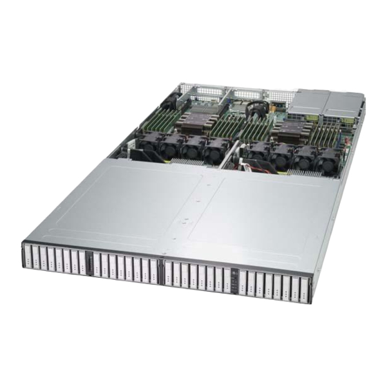
Chapter 1: Introduction Front Features The SC136HTS-R1K69P-R2 is a 1U chassis. See the illustration below for the features included on the front of the chassis. Figure 1-2. Chassis Front View Front Chassis Features Item Feature Description Control Panel Front control panel with LEDs and buttons (see preceding page) Drive Bays Hot-swappable Ruler SSDs (Drive IDs: 0 to 7) Drive Bays... -
Page 12: Rear Features
SuperServer 1029P-NR32R User's Manual Rear Features The illustration below shows the features included on the rear of the chassis. Figure 1-3. Chassis Rear View Rear Chassis Features Item Feature Description This is the 1600W power supply module with LED and there are two modules Power Supply for power redundancy. -
Page 13: Motherboard Layout
Chapter 1: Introduction 1.5 Motherboard Layout Below is a layout of the X11DPS-RE with jumper, connector and LED locations shown. See the table on the following page for descriptions. For detailed descriptions, pinout information and jumper settings, refer to Chapter 4. S-SATA5 IPMI_ JCOM1... -
Page 14: Quick Reference Table
SuperServer 1029P-NR32R User's Manual Quick Reference Table Jumper Description Default Setting JBT1 CMOS Clear Open (Normal) JPB1 BMC Enable/Disable Pins 1-2 (Enabled) JPG1 VGA Enable/Disable Pins 1-2 (Enabled) JPQAT QAT Enable/Disable Pins 1-2 (Enabled) JPL1 GLAN Enable/Disable Pins 1-2 (Enabled) - Page 15 Chapter 1: Introduction Connector Description S-SATA4~5 (Powered) SATA connectors with power-pins built-in with support of SuperDOM JLAN1/JLAN2 10G LAN ports 1 and 2 VGA port M.2 SLOT 1 M.2 SLOT 2 Note: To avoid causing interference with other components, please be sure to use an add-on card that is fully compliant with the PCI-standard on a PCI slot.
-
Page 16: Chapter 2 System Installation
SuperServer 1029P-NR32R User's Manual Chapter 2 System Installation 2.1 Overview This chapter provides advice and instructions for mounting your system in a server rack. If your system is not already fully integrated with drives, fans etc., refer to Chapter 3 for details on installing those specific components. -
Page 17: System Precautions
Chapter 2: System Installation • In single rack installations, stabilizers should be attached to the rack. In multiple rack in- stallations, the racks should be coupled together. • Always verify that the rack is stable before extending a server or other component from the rack. -
Page 18: Circuit Overloading
SuperServer 1029P-NR32R User's Manual Circuit Overloading Consideration should be given to the connection of the equipment to the power supply circuitry and the effect that any possible overloading of circuits might have on overcurrent protection and power supply wiring. Appropriate consideration of equipment nameplate ratings should be used when addressing this concern. -
Page 19: Installing The System Into A Rack
Chapter 2: System Installation 2.3 Installing the System into a Rack This section provides information on installing the SC136HTS-R1K69P-R2 chassis into a rack unit with the rails provided. Due to the variety of rack units on the market, the assembly procedure might differ slightly. -
Page 20: Releasing The Inner Rails
SuperServer 1029P-NR32R User's Manual Releasing the Inner Rails Releasing the Inner Rails from the Outer Rails 1. Pull the inner rail out of the outer rail until it is fully extended as illustrated below. 2. Press the locking tab down to release the inner rail. -
Page 21: Installing The Inner Rails On The Chassis
Chapter 2: System Installation Installing the Inner Rails on the Chassis Installing the Inner Rails 1. Place the inner rail firmly against the side of the chassis, aligning the hooks on the side of the chassis with the holes in the inner rail. 2. -
Page 22: Installing The Outer Rails On The Rack
SuperServer 1029P-NR32R User's Manual Installing the Outer Rails on the Rack Installing the Outer Rails 1. If your rack has round mounting holes, adjust the fittings on the outer rails. Press the latch at the end of the rail to change from square fittings to round fittings. - Page 23 Chapter 2: System Installation 2. Push the middle rail back into the outer rail. An audible click indicates that the rail is fully inserted. Figure 2-5. Adjusting the Middle Rail 3. Insert the pegs on the rear of the outer rail into the rear rack holes. An audible click indicates that the rail is locked into place.
-
Page 24: Installing The Chassis Onto The Rack
SuperServer 1029P-NR32R User's Manual Installing the Chassis onto the Rack Installing the Chassis onto the Rack 1. Fully extend the middle rails as illustrated in Figure 2-7. 2. Align the inner rails of the chassis with the middle rails on the rack. -
Page 25: Chapter 3 Maintenance And Component Installation
SuperServer 1029P-NR32R User's Manual Chapter 3 Maintenance and Component Installation This chapter provides instructions on installing and replacing main system components. To prevent compatibility issues, only use components that match the specifications and/or part numbers given. Installation or replacement of most components require that power first be removed from the system. - Page 26 Chapter 3: Maintenance and Component Installation Warning: Except for short periods of time, do not operate the system without the cover in place. The chassis cover must be in place to allow for proper airflow and to prevent overheating. Figure 3-1. Removing the Chassis Cover...
-
Page 27: Processor And Heatsink Installation
Thermal grease is pre-applied on a new heatsink. No additional thermal grease is needed. • Refer to the Supermicro website for updates on processor support. • All graphics in this manual are for illustrations only. Your components may look different. -
Page 28: Overview Of The Processor Carrier Assembly
Chapter 3: Maintenance and Component Installation Overview of the Processor Carrier Assembly The processor carrier assembly contains the Intel Xeon Non-Fabric (Non-F) processor and a processor carrier. 1. Non-F Processor 2. Processor Carrier Overview of the CPU Socket The CPU socket is protected by a plastic protective cover. 1. -
Page 29: Overview Of The Processor Heatsink Module
SuperServer 1029P-NR32R User's Manual Overview of the Processor Heatsink Module The Processor Heatsink Module (PHM) contains a heatsink, a processor carrier, and the Intel Xeon Non-Fabric (Non-F) processor. 1. Heatsink with Thermal Grease 2. Processor Carrier 3. Non-F Processor Processor Heatsink Module... -
Page 30: Creating The Non-F Model Processor Carrier Assembly
Chapter 3: Maintenance and Component Installation Creating the Non-F Model Processor Carrier Assembly To install a Non-F model processor into the processor carrier, follow the steps below: 1. Hold the processor with the LGA lands (gold contacts) facing up. Locate the small, gold triangle in the corner of the processor and the corresponding hollowed triangle on the processor carrier. -
Page 31: Assembling The Processor Heatsink Module
SuperServer 1029P-NR32R User's Manual Assembling the Processor Heatsink Module After creating the processor carrier assembly for the Non-F model processor, mount it onto the heatsink to create the processor heatsink module (PHM): 1. Note the label on top of the heatsink, which marks the heatsink mounting holes as 1, 2, 3, and 4. -
Page 32: Preparing The Cpu Socket For Installation
Chapter 3: Maintenance and Component Installation Preparing the CPU Socket for Installation This motherboard comes with a plastic protective cover installed on the CPU socket. Remove it from the socket to install the Processor Heatsink Module (PHM). Gently pull up one corner of the plastic protective cover to remove it. -
Page 33: Installing The Processor Heatsink Module (Phm)
SuperServer 1029P-NR32R User's Manual Installing the Processor Heatsink Module (PHM) 1. Once you have assembled the processor heatsink module (PHM) by following the instructions, you are ready to install the processor heatsink module (PHM) into the CPU socket on the motherboard. To install the PHM into the CPU socket, follow the instructions below. -
Page 34: Removing The Processor Heatsink Module (Phm) From The Motherboard
Chapter 3: Maintenance and Component Installation Removing the Processor Heatsink Module (PHM) from the Motherboard Before removing the processor heatsink module (PHM), unplug power cord from the power outlet. 1. Using a T30 Torx-bit screwdriver, turn the screws on the PHM counterclockwise to loosen them from the socket, starting with screw marked #4 (in the sequence of 4, 3, 2, 2. -
Page 35: Memory Installation
16 GB 2666 SRx8 4 GB 8 GB 2666 RDIMM DRx8 8 GB 16 GB 2666 DRx4 16 GB 32 GB 2666 QRX4 2H-64GB 2666 RDIMM 3Ds 8RX4 4H-128GB 2666 Check the Supermicro website for possible updates to memory support. -
Page 36: Memory Population Guidelines
Then, if using two DIMMs per channel, install the second DIMM in the black slot. The following memory population sequence table was created based on guidelines provided by Intel to support Supermicro motherboards. The diagram is for illustrative purposes; your motherboard may look different. - Page 37 SuperServer 1029P-NR32R User's Manual Memory Population for X11 DP Motherboard, 24 DIMM Slots When 1 CPU is used: Memory Population Sequence 1 CPU & 1 DIMM CPU1: P1-DIMMA1 1 CPU & 2 DIMMs CPU1: P1-DIMMA1/P1-DIMMD1 1 CPU & 3 DIMMs CPU1: P1-DIMMC1/P1-DIMMB1/P1-DIMMA1 1 CPU &...
- Page 38 Chapter 3: Maintenance and Component Installation Memory Population for X11 DP Motherboard, 24 DIMM Slots CPU1: P1-DIMMC1/P1-DIMMC2/P1-DIMMB1/P1-DIMMB2/P1-DIMMA1/P1-DIMMA2/ P1-DIMMD2/P1-DIMMD1/P1-DIMME2/P1-DIMME1/P1-DIMMF2/P1-DIMMF1 2 CPUs & 20 DIMMs CPU2: P2-DIMMB1/P2-DIMMB2/P2-DIMMA1/P2-DIMMA2/P2-DIMMD2/P2-DIMMD1/ P2-DIMME2/P2-DIMME1 CPU1: P1-DIMMC1/P1-DIMMC2/P1-DIMMB1/P1-DIMMB2/P1-DIMMA1/P1-DIMMA2/ 2 CPUs & 22 DIMMs P1-DIMMD2/P1-DIMMD1/P1-DIMME2/P1-DIMME1/P1-DIMMF1 (Unbalanced: not CPU2: P2-DIMMC1/P2-DIMMC2/P2-DIMMB1/P2-DIMMB2/P2-DIMMA1/P2-DIMMA2/ recommended) P2-DIMMD2/P2-DIMMD1/P2-DIMME2/P2-DIMME1/P2-DIMMF1 CPU1: P1-DIMMC1/P1-DIMMC2/P1-DIMMB1/P1-DIMMB2/P1-DIMMA1/P1-DIMMA2/ P1-DIMMD2/P1-DIMMD1/P1-DIMME2/P1-DIMME1/P1-DIMMF2/P1-DIMMF1 2 CPUs &...
-
Page 39: Dimm Installation
SuperServer 1029P-NR32R User's Manual DIMM Installation JUIDB2 LED1 JCOM1 JPL1 JSDCARD1 JUSB1 JIPMILAN S-SATA5 S-SATA4 USB12/13(3.0) 1. Follow the instructions given in the LED3 JTPM1 JLAN2 JLAN1 LED4 JRK1 JSD1 JSD2 memory population guidelines listed in JPWR1 the previous sections to install memory... -
Page 40: Pci Expansion Card Installation
Chapter 3: Maintenance and Component Installation PCI Expansion Card Installation The system includes two pre-installed riser cards (RSC-R1U-E16R) that allow you to position standard size PCI-E cards at a 90-degree angle, allowing them to fit inside the chassis. Installing PCI Expansion Cards The riser cards have already been pre-installed into the motherboard. -
Page 41: Chassis Components
RSSDs (Ruler SSDs). This section is intended to address the need to prepare PCIe NVMe SSD to be hot-plugged in Supermicro SuperServer SYS-1029P-NR32R & SYS-1029P-N32R systems. Warning: Hot removing an NVMe SSD from any deployed systems requires careful planning. If possible, it is generally a good idea to stop the IO access to the target NVMe SSD and migrate out its data first. - Page 42 Chapter 3: Maintenance and Component Installation 2. Find the slot information of the target NVMe SSD. In the server BMC GUI (under Server Health / NVMe SSD), the probed target NVMe SSD information can be used find its slot location in the enclosure: As shown in above BMC GUI screen shot, the target NVMe SSD is in Slot 22, with its Vendor / Model / Serial matching what we probed.
- Page 43 SuperServer 1029P-NR32R User's Manual Confirm the eject operation by clicking the “OK” button on the following pop-up window. Once the GUI indicates that the NVMe SSD has been rejected successfully, the target is removed from the OS. To confirm that target SSD has been removed from OS, do the following: •...
-
Page 44: Removing A Drive Using Windows
Chapter 3: Maintenance and Component Installation Removing a Drive Using Windows Examples listed here were done under Windows Server 2016. Command output in this section maybe abbreviated for easier reading. Additional notes are added with marking “”. Windows generally reports NVMe SSD events associated with a disk or harddisk number. In this section, a method is shown how to correlate an NVMe SSD’s slot number in a server enclosure to its Disk #, and prepare the target SSD for hot removal. - Page 45 SuperServer 1029P-NR32R User's Manual Also, with Intel SSD data center tool, all the installed Intel SSD information could be listed with the following command: #isdct show –intelssd … - Intel SSD DC P4500 Series BTLF736500FD4P0SGN - Serial number Bootloader : 0136 DevicePath : \\\\.\\PHYSICALDRIVE12...
- Page 46 Chapter 3: Maintenance and Component Installation 3. Prepare the target NVMe SSD for hot removal. On the BMC GUI, once the target NVMe SSD has been correctly identified, click the Eject button for its slot to remove it from the Confirm the eject operation by clicking the “OK”...
-
Page 47: References
4. Hot insert the replacement NVMe SSD. The replacement NVMe SSD could simply be hot inserted. After Windows discovers the newly inserted SSD, it will be ready for configuration and access. References Internal References Supermicro SuperServer SYS-1029P-N32R information and documents: https://www.supermicro.com/products/system/1U/1029/SYS-1029P-N32R.cfm Supermicro SuperServer SYS-1029P-NR32R information and documents: https://www.supermicro.com/products/system/1U/1029/SYS-1029P-NR32R.cfm External References Intel SSD Data Center Tool information and downloads: https://downloadcenter.intel.com/download/27863?v=t... -
Page 48: System Cooling
Chapter 3: Maintenance and Component Installation System Cooling Eight 4-cm hot-swap fans provide the cooling for the system. It is very important that the chassis top cover is properly installed and forms a seal in order for the cooling air to circulate properly through the chassis and cool the components. -
Page 49: Power Supply
If either of the two power supply modules fail, the other will take the full load and allow the system to continue operation without interruption. The Power Fail LED illuminates until the failed module has been replaced. Replacements can be ordered directly from Supermicro (see contact information in the Preface). The power supply modules have a hot-swap capability, so you can replace the failed module without powering down the system. -
Page 50: Pci-E Expansion Cards
Chapter 3: Maintenance and Component Installation PCI-E Expansion Cards The 1029P-NR32R can accommodate up to two low-profile PCI-E expansion cards in the rear slots. Installing an Add-on Card Begin by removing power from the system as described in Section 3.1 and removing the cover as described in Section 3.2. -
Page 51: Chapter 4 Motherboard Connections
8-pin Processor Power (JPWR1/JPWR2) SMCI-Proprietary Power Connectors Two SMCI-proprietary Power Supply Unit connectors, located at PSU1/PSU2, provide main power to your system. Please note that these power connectors are reserved for Supermicro system use only. PCIE-Proprietary Power Connectors JPWR1/2 are 12-pin power connectors used by proprietary PCIE-based memory backplane designs. -
Page 52: Front Control Panel
JF1 contains header pins for various buttons and indicators that are normally located on a control panel at the front of the chassis. These connectors are designed specifically for use with Supermicro chassis. See the figure below for the descriptions of the front control panel buttons and LED indicators. - Page 53 Chapter 4: Motherboard Connections Power Button The Power Button connection is located on pins 1 and 2 of JF1. Momentarily contacting both pins will power on/off the system. This button can also be configured to function as a suspend button (with a setting in the BIOS - see Chapter 4). To turn off the power when the system is in suspend mode, press the button for 4 seconds or longer.
- Page 54 SuperServer 1029P-NR32R User's Manual Fan Fail and UID LED Connect an LED cable to pins 7 and 8 of the Front Control Panel to use the Overheat/Fan Fail LED connections. The LED on pin 8 provides warnings of overheat or fan failure. The blue LED on pin 7 works as the front panel UID LED indicator.
- Page 55 (Note: UID can also be triggered via IPMI on the motherboard. For more information, please refer to the IPMI User's Guide posted on our website at http://www.supermicro.com.) UID Switch Pin Definitions...
-
Page 56: Rear I/O Ports
SuperServer 1029P-NR32R User's Manual 4.3 Rear I/O Ports See Figure 4-2 below for the locations and descriptions of the various I/O ports on the rear of the motherboard. JUIDB2 LED1 JCOM1 JPL1 JSDCARD1 JUSB1 JIPMILAN S-SATA5 S-SATA4 USB12/13(3.0) LED3 JLAN2... -
Page 57: Ethernet Ports
Chapter 4: Motherboard Connections Serial Port There are two COM connectors (JCOM1/JCOM2) near the I/O back panel, next to the IPMI LAN connector. These COM connectors provide serial communication support. See the table below for pin definitions. VGA Port There is one VGA port on the IO back panel. Connect to this port for the VGA display. COM Connector (JCOM1/2) Pin Definitions Pin#... -
Page 58: Headers And Connectors
SuperServer 1029P-NR32R User's Manual 4.4 Headers and Connectors Onboard Fan Header This motherboard has eight headers (FAN1~8). All these 4-pin fan headers are backward- compatible with traditional 3-pin fans. However, onboard fan speed control is available only when all 4-pin fans are used on the motherboard. Fan speed control is supported by Thermal Management via IPMI 2.0 interface. - Page 59 Chapter 4: Motherboard Connections NVMe Slots (PCI-E 3.0 x32) There are two PCI-E 3.0 x32 slots with Tray Cable Connector Interface connections on the motherboard. PCI-E 3.0 Slots There are two PCI-E 3.0 x16 slots located on the motherboard. CPU1 SLOT1 PCI-E and CPU2 SLOT2 PCI-E are supported by their corresponding CPU's, and offer riser card support.
- Page 60 The X11DPS-RE has two SATA DOM 3.0 ports (S-SATA4, S-SATA5). S-SATA4/S-SATA5 can be used with Supermicro SuperDOMs which are yellow SATA DOM connectors with power pins built in, and do not require external power cables. Supermicro SuperDOMs are backward-compatible with regular SATA HDDs or SATA DOMs that need external power cables.
-
Page 61: Jumpers
Chapter 4: Motherboard Connections 4.5 Jumpers Explanation of Jumpers To modify the operation of the motherboard, jumpers are used to choose between optional settings. Jumpers create shorts between two pins to change the function associated with it. Pin 1 is identified with a square solder pad on the printed circuit board. See the motherboard layout page for jumper locations. - Page 62 SuperServer 1029P-NR32R User's Manual BIOS Recovery The default setting is on pins 1 and 2 of jumper JBR1 for normal operation (Normal). For BIOS recovery, close pins 2-3. Refer to the table below for jumper settings. BIOS Recovery Jumper Settings...
-
Page 63: Led Indicators
Chapter 4: Motherboard Connections Watch Dog Timer The Watch Dog function is a monitor controlled by the JWD1 that can reboot the system when a software application hangs. It must be enabled in BIOS, where the default is set to Reset. - Page 64 SuperServer 1029P-NR32R User's Manual Onboard Power LED The Onboard Power LED is located at LE2 on the motherboard. When this LED is on, the system is also on. Be sure to turn off the system and unplug the power cord before removing or installing components.
-
Page 65: Chapter 5 Software
You must first configure RAID settings (if using RAID) before you install the Windows OS and the software drivers. To configure RAID settings, please refer to the RAID Configuration User Guides posted on our website at www.supermicro.com/support/manuals. Installing the Windows OS for a RAID System 1. -
Page 66: Driver Installation
SuperServer 1029P-NR32R User's Manual 5.2 Driver Installation The Supermicro FTP site contains drivers and utilities for your system at ftp://ftp.supermicro. com. Some of these must be installed, such as the chipset driver. After accessing the FTP site, go into the CDR_Images directory and locate the ISO file for your motherboard. -
Page 67: Superdoctor ® 5
5.3 SuperDoctor ® The Supermicro SuperDoctor 5 is a program that functions in a command-line or web-based interface for Windows and Linux operating systems. The program monitors such system health information as CPU temperature, system voltages, system power consumption, fan speed, and provides alerts via email or Simple Network Management Protocol (SNMP). -
Page 68: Ipmi
SuperServer 1029P-NR32R User's Manual 5.4 IPMI The X11DPS-RE supports the Intelligent Platform Management Interface (IPMI). IPMI is used to provide remote access, monitoring and management. There are several BIOS settings that are related to IPMI. For general documentation and information on IPMI, please visit our website at:... -
Page 69: Chapter 6 Bios
Chapter 6: BIOS Chapter 6 BIOS 6.1 Introduction This chapter describes the AMIBIOS™ Setup utility for the X11DPS-RE motherboard. The BIOS is stored on a chip and can be easily upgraded using a flash program. Note: Due to periodic changes to the BIOS, some settings may have been added or deleted and might not yet be recorded in this manual. -
Page 70: Main Menu
SuperServer 1029P-NR32R User's Manual 6.2 Main Menu When you first enter the AMI BIOS setup utility, you will enter the Main setup screen. You can always return to the Main setup screen by selecting the Main tab on the top of the screen. The Main BIOS setup screen is shown below. -
Page 71: Advanced Setup Configurations
Chapter 6: BIOS CPLD Version This item displays the version of the CPLD (Complex-Programmable Logical Device) used in the system. Memory Information Total Memory This item displays the total size of memory available in the system. 4.3 Advanced Setup Configurations Use the arrow keys to select the Advanced submenu and press <Enter>... - Page 72 SuperServer 1029P-NR32R User's Manual Boot Feature Quiet Boot Use this feature to select the screen between displaying POST messages or the OEM logo at bootup. Select Disabled to display the POST messages. Select Enabled to display the OEM logo instead of the normal POST messages. The options are Enabled and Disabled.
- Page 73 Chapter 6: BIOS Power Button Function This feature controls how the system shuts down when the power button is pressed. Select 4 Seconds Override for the user to power off the system after pressing and holding the power button for 4 seconds or longer. Select Instant Off to instantly power off the system as soon as the user presses the power button.
- Page 74 SuperServer 1029P-NR32R User's Manual Hyper-Threading (ALL) Select Enable to use Intel Hyper-Threading Technology to enhance CPU performance. The options are Disabled and Enabled. Cores Enabled Use this feature to enable or disable CPU cores in the processor specified by the user. Enter 0 to enable all cores available in the processor.
- Page 75 Chapter 6: BIOS DCU IP Prefetcher If this item is set to Enable, the IP prefetcher in the DCU (Data Cache Unit) will prefetch IP addresses to improve network connectivity and system performance. The options are Enable and Disable. LLC Prefetch If this feature is set to Enable, LLC (hardware cache) prefetching on all threads will be supported.
- Page 76 SuperServer 1029P-NR32R User's Manual CPU P State Control SpeedStep (PStates) EIST (Enhanced Intel SpeedStep Technology) allows the system to automatically adjust processor voltage and core frequency in an effort to reduce power consumption and heat dissipation. Please refer to Intel’s website for detailed information. The options are Disable and Enable.
- Page 77 Chapter 6: BIOS Enhanced Halt State (C1E) Select Enable to enable "Enhanced Halt State" support, which will significantly reduce the CPU's power consumption by minimizing CPU's clock cycles and reduce voltage during a "Halt State." The options are Disable and Enable. Package C State Control Package C State Use this feature to set the limit on the C-State package register.
- Page 78 SuperServer 1029P-NR32R User's Manual Link L0p Enable Select Enable to enable Link L0p. The options are Disable, Enable, and Auto. Link L1 Enable Select Enable to enable Link L1 (Level 1 link). The options are Disable, Enable, and Auto. IO Directory Cache Select Enable for the IODC (I/O Directory Cache) to generate snoops instead of generating memory lockups for remote IIO (InvIToM) and/or WCiLF (Cores).
- Page 79 Chapter 6: BIOS Memory Configuration Enforce POR Select POR to enforce POR restrictions for DDR4 memory frequency and voltage programming. The options are POR and Disable. Memory Frequency Use this feature to set the maximum memory frequency for onboard memory modules. The options are Auto, 1866, 2000, 2133, 2200, 2400, 2600, and 2666.
- Page 80 SuperServer 1029P-NR32R User's Manual Memory RAS (Reliability_Availability_Serviceability) Configuration Use this submenu to configure the following Memory RAS settings. Mirror Mode Select Enable to set all 1LM/2LM memory installed in the system on the mirror mode, which will create a duplicate copy of data stored in the memory to increase memory security, but it will reduce the memory capacity into half.
- Page 81 Chapter 6: BIOS Patrol Scrub Patrol Scrubbing is a process that allows the CPU to correct correctable memory errors detected in a memory module and send the corrections to the requestor (the original source). When this item is set to Enable, the IO hub will read and write back one cache line every 16K cycles if there is no delay caused by internal processing.
- Page 82 SuperServer 1029P-NR32R User's Manual MCP1 (IIO PCIe Br5) This item configures the PCI-E Bifuraction setting for a PCI-E port specified by the user. The options are x16 and Auto. Socket 0 PcieBr0D00F0 - Port 0/DMI PcieBr1D00F0 - Port 1A PcieBr2D00F0 -...
- Page 83 Chapter 6: BIOS Intel VT for Directed I/O (VT-d) Intel® VT for Directed I/O (VT-d) Select Enable to use Intel Virtualization Technology support for Direct I/O VT-d by reporting the I/O device assignments to the VMM (Virtual Machine Monitor) through the DMAR ACPI tables.
- Page 84 SuperServer 1029P-NR32R User's Manual PassThrough DMA Use this feature to allow devices such as network cards to access the system memory without using a processor. Select Enable to use the Non-Isoch VT_D Engine Pass Through Direct Memory Access (DMA) support. The options are Enable and Disable.
- Page 85 Chapter 6: BIOS South Bridge The following South Bridge information will display: • USB Module Version • USB Devices Legacy USB Support Select Enabled to support onboard legacy USB devices. Select Auto to disable legacy support if there are no legacy USB devices present. Select Disable to have all USB devices available for EFI applications only.
- Page 86 SuperServer 1029P-NR32R User's Manual Server ME (Management Engine) Configuration This feature displays the following General ME Configuration settings. Operational Firmware Version Backup Firmware Version Recovery Firmware Version ME Firmware Status #1 ME Firmware Status #2 Current State Error Code SATA Configuration ...
- Page 87 Chapter 6: BIOS SATA RAID Option ROM/UEFI Driver (Available when the item "Configure SATA as" is set to "RAID") Select EFI to load the EFI driver for system boot. Select Legacy to load a legacy driver for system boot. The options are Disable, EFI, and Legacy. SATA Port 0 - SATA Port 7 Hot Plug Select Enable to support Hot-plugging for the device installed on a selected SATA port...
- Page 88 SuperServer 1029P-NR32R User's Manual Aggressive Link Power Management When this item is set to Enable, the sSATA AHCI controller manages the power use of the SATA link. The controller will put the link in a low power mode during an extended period of I/O inactivity, and will return the link to an active state when I/O activity resumes.
- Page 89 Chapter 6: BIOS MMIO High Base Use this item to select the base memory size according to memory-address mapping for the IO hub. The base memory size must be between 4032G to 4078G. The options are 56T, 48T, 24T, 16T, 4T, and 1T. MMIO High Granularity Size Use this item to select the high memory size according to memory-address mapping for the IO hub.
- Page 90 SuperServer 1029P-NR32R User's Manual Onboard LAN2 Option ROM Use this feature to select the type of device installed in LAN Port2 used for system boot. The options are Legacy, EFI and Disabled. Network Stack Configuration Network Stack Select Enabled to enable PXE (Preboot Execution Environment) or UEFI (Unified Extensible Firmware Interface) for network stack support.
- Page 91 Chapter 6: BIOS Super IO Configuration Super IO Chip AST2500 Serial Port 1 Configuration Serial Port 1 Select Enabled to enable the onboard serial port specified by the user. The options are Disabled and Enabled. Device Settings This item displays the base I/O port address and the Interrupt Request address of a serial port specified by the user.
- Page 92 SuperServer 1029P-NR32R User's Manual Serial Port 2 Attribute Select SOL to use COM Port 2 as a Serial_Over_LAN (SOL) port for console redirection. The options are SOL and COM. Serial Port Console Redirection COM 1 Console Redirection Select Enabled to enable COM Port 1 for Console Redirection, which will allow a client machine to be connected to a host machine at a remote site for networking.
- Page 93 Chapter 6: BIOS Flow Control Use this feature to set the flow control for Console Redirection to prevent data loss caused by buffer overflow. Send a "Stop" signal to stop sending data when the receiving buffer is full. Send a "Start" signal to start sending data when the receiving buffer is empty. The options are None and Hardware RTS/CTS.
- Page 94 SuperServer 1029P-NR32R User's Manual Console Redirection Settings (for SOL) Use this feature to specify how the host computer will exchange data with the client computer, which is the remote computer used by the user. Terminal Type Use this feature to select the target terminal emulation type for Console Redirection.
- Page 95 Chapter 6: BIOS Recorder Mode Select Enabled to capture the data displayed on a terminal and send it as text messages to a remote server. The options are Disabled and Enabled. Resolution 100x31 Select Enabled for extended-terminal resolution support. The options are Disabled and Enabled.
- Page 96 SuperServer 1029P-NR32R User's Manual Console Redirection Settings (EMS) Out-of-Band Management Port The feature selects a serial port in a client server to be used by the Windows Emergency Management Services (EMS) to communicate with a remote host server. The options are COM1 and SOL.
- Page 97 Chapter 6: BIOS High Precision Timer Select Enabled to activate the High Precision Event Timer (HPET) that produces periodic interrupts at a much higher frequency than a Real-time Clock (RTC) does in synchronizing multimedia streams, providing smooth playback and reducing the dependency on other timestamp calculation devices, such as an x86 RDTSC Instruction embedded in the CPU.
- Page 98 SuperServer 1029P-NR32R User's Manual Security Device Support If this feature and the TPM jumper (JPT1 if installed onboard) on the motherboard are both enabled, the onboard security (TPM) device will be enabled in the BIOS to enhance data integrity and system security. Please note that the OS will not show the security device.
-
Page 99: Event Logs
(Device Function On-Hide) support for the system to work properly. (EV DFX is under "IIO Configuration" in the "Chipset/North Bridge" submenu). Note 2: For more information on TPM, please refer to the TPM manual at http://www. supermicro.com/manuals/other. 6.4 Event Logs Use this feature to configure Event Log settings. - Page 100 SuperServer 1029P-NR32R User's Manual Change SMBIOS Event Log Settings Enabling/Disabling Options SMbios Event Log Select Enabled to enable SMBIOS (System Management BIOS) Event Logging during system boot. The options are Disabled. and Enabled. Erasing Settings Erase Event Log Select Enabled to erase all error events in the SMBIOS (System Management BIOS) log before an event logging is initialized at bootup.
-
Page 101: Ipmi
Chapter 6: BIOS View SMBIOS Event Log This item allows the user to view the event in the system event log. Select this item and press <Enter> to view the status of an event in the log. The following categories are displayed: Date/Time/Error Code/Severity 6.5 IPMI Use this feature to configure Intelligent Platform Management Interface (IPMI) settings. - Page 102 SuperServer 1029P-NR32R User's Manual System Event Log Enabling/Disabling Options SEL Components Select Enabled for all system event logging at bootup. The options are Disabled and Enabled. Erasing Settings Erase SEL Select Yes, On next reset to erase all system event logs upon next system reboot. Select Yes, On every reset to erase all system event logs upon each system reboot.
- Page 103 Chapter 6: BIOS Current Configuration Address source This feature allows the user to select the source of the IP address for this computer. If Static is selected, you will need to know the IP address of this computer and enter it to the system manually in the field.
-
Page 104: Security Settings
SuperServer 1029P-NR32R User's Manual 6.6 Security Settings This menu allows the user to configure the following security settings for the system. Administrator Password Use this feature to set the administrator password which is required to enter the BIOS setup utility. The length of the password should be from 3 characters to 20 characters long. - Page 105 Chapter 6: BIOS Secure Boot When you select this submenu and press the <Enter> key, the following items will display: • System Mode • Secure Boot • Vendor Keys Attempt Secure Boot Use this item to enable secure boot. The options are Disabled and Enabled. Secure Boot Mode Use this feature to select the desired secure boot mode for the system.
- Page 106 SuperServer 1029P-NR32R User's Manual Platform Key (PK) This feature allows the user to enter and configure a set of values to be used as a platform firmware key for the system. This set of values also indicate the size, the keys numbers, and the key source of the Platform Key.
-
Page 107: Boot Settings
Chapter 6: BIOS 6.7 Boot Settings Use this feature to configure Boot Settings: Boot Mode Select Use this feature to select the type of devices that the system is going to boot from. The options are Legacy, UEFI (Unified Extensible Firmware Interface), and Dual. Legacy to EFI support The options are Disabled and Enabled. - Page 108 SuperServer 1029P-NR32R User's Manual When the item above -"Boot Mode Select" is set to UEFI, the following items will be display for configuration: • Boot Option #1 - Boot Option #9 Delete Boot Option This feature allows the user to select a boot device to delete from the boot priority list.
-
Page 109: Save & Exit
Chapter 6: BIOS 6.8 Save & Exit Select the Save & Exit tab from the BIOS setup screen to configure the settings below. Save Options Discard Changes and Exit Select this option to quit the BIOS setup without making any permanent changes to the system configuration and reboot the computer. - Page 110 SuperServer 1029P-NR32R User's Manual Discard Changes Select this option and press <Enter> to discard all the changes and return to the AMI BIOS setup utility. Default Options Restore Optimized Defaults To set this feature, select Restore Defaults from the Exit menu and press <Enter> to load manufacturer default settings which are intended for maximum system performance but not for maximum stability.
-
Page 111: Appendix A Bios Error Codes
Appendix A: BIOS Error Codes Appendix A BIOS Error Codes A-1 BIOS Error Beep (POST) Codes During the POST (Power-On Self-Test) routines, which are performed each time the system is powered on, errors may occur. Non-fatal errors are those which, in most cases, allow the system to continue the boot-up process. - Page 112 When BIOS performs the Power On Self Test, it writes checkpoint codes to I/O port 0080h. If the computer cannot complete the boot process, a diagnostic card can be attached to the computer to read I/O port 0080h (Supermicro p/n AOC-LPC80-20). For information on AMI updates, please refer to http://www.ami.com/products/.
-
Page 113: About Standardized Warning Statements
Supermicro's Technical Support department for assistance. Only certified technicians should attempt to install or configure components. Read this appendix in its entirety before installing or configuring components in the Supermicro chassis. These warnings may also be found on our website at http://www.supermicro.com/about/... - Page 114 Appendix B: Standardized Warning Statements Warnung WICHTIGE SICHERHEITSHINWEISE Dieses Warnsymbol bedeutet Gefahr. Sie befinden sich in einer Situation, die zu Verletzungen führen kann. Machen Sie sich vor der Arbeit mit Geräten mit den Gefahren elektrischer Schaltungen und den üblichen Verfahren zur Vorbeugung vor Unfällen vertraut. Suchen Sie mit der am Ende jeder Warnung angegebenen Anweisungsnummer nach der jeweiligen Übersetzung in den übersetzten Sicherheitshinweisen, die zusammen mit diesem Gerät ausgeliefert wurden.
- Page 115 SuperServer 1029P-NR32R User's Manual . ٌ ا ك ً ف حالة و ٌ يك أى تتسبب ف اصابة جسذ ة ٌ هذا الزهز ع ٌ خطز !تحذ ز قبل أى تعول عىل أي هعذات،يك عىل علن بالوخاطز ال ا ٌجوة عي الذوائز...
- Page 116 Appendix B: Standardized Warning Statements Warnung Vor dem Anschließen des Systems an die Stromquelle die Installationsanweisungen lesen. ¡Advertencia! Lea las instrucciones de instalación antes de conectar el sistema a la red de alimentación. Attention Avant de brancher le système sur la source d'alimentation, consulter les directives d'installation. .יש...
- Page 117 SuperServer 1029P-NR32R User's Manual Warnung Dieses Produkt ist darauf angewiesen, dass im Gebäude ein Kurzschluss- bzw. Überstromschutz installiert ist. Stellen Sie sicher, dass der Nennwert der Schutzvorrichtung nicht mehr als: 250 V, 20 A beträgt. ¡Advertencia! Este equipo utiliza el sistema de protección contra cortocircuitos (o sobrecorrientes) del edificio.
- Page 118 Appendix B: Standardized Warning Statements Power Disconnection Warning Warning! The system must be disconnected from all sources of power and the power cord removed from the power supply module(s) before accessing the chassis interior to install or remove system components. 電源切断の警告...
- Page 119 SuperServer 1029P-NR32R User's Manual يجب فصم اننظاو من جميع مصادر انطاقت وإ ز انت سهك انكهرباء من وحدة امداد انطاقت قبم انىصىل إىن امنناطق انداخهيت نههيكم نتثبيج أو إ ز انت مكىناث الجهاز 경고! 시스템에 부품들을 장착하거나 제거하기 위해서는 섀시 내부에 접근하기 전에 반드시 전원...
- Page 120 Appendix B: Standardized Warning Statements Attention Il est vivement recommandé de confier l'installation, le remplacement et la maintenance de ces équipements à des personnels qualifiés et expérimentés. !אזהרה .צוות מוסמך בלבד רשאי להתקין, להחליף את הציוד או לתת שירות עבור הציוד واملدربيه...
- Page 121 SuperServer 1029P-NR32R User's Manual Warnung Diese Einheit ist zur Installation in Bereichen mit beschränktem Zutritt vorgesehen. Der Zutritt zu derartigen Bereichen ist nur mit einem Spezialwerkzeug, Schloss und Schlüssel oder einer sonstigen Sicherheitsvorkehrung möglich. ¡Advertencia! Esta unidad ha sido diseñada para instalación en áreas de acceso restringido. Sólo puede obtenerse acceso a una de estas áreas mediante la utilización de una herramienta especial,...
- Page 122 Appendix B: Standardized Warning Statements Battery Handling Warning! There is the danger of explosion if the battery is replaced incorrectly. Replace the battery only with the same or equivalent type recommended by the manufacturer. Dispose of used batteries according to the manufacturer's instructions 電池の取り扱い...
- Page 123 SuperServer 1029P-NR32R User's Manual هناك خطر من انفجار يف حالة اسحبذال البطارية بطريقة غري صحيحة فعليل اسحبذال البطارية فقط بنفس النىع أو ما يعادلها مام أوصث به الرشمة املصنعة جخلص من البطاريات املسحعملة وفقا لحعليامت الرشمة الصانعة 경고! 배터리가 올바르게 교체되지 않으면 폭발의 위험이 있습니다. 기존 배터리와 동일하거나 제...
- Page 124 Appendix B: Standardized Warning Statements ¡Advertencia! Puede que esta unidad tenga más de una conexión para fuentes de alimentación. Para cortar por completo el suministro de energía, deben desconectarse todas las conexiones. Attention Cette unité peut avoir plus d'une connexion d'alimentation. Pour supprimer toute tension et tout courant électrique de l'unité, toutes les connexions d'alimentation doivent être débranchées.
- Page 125 SuperServer 1029P-NR32R User's Manual Backplane Voltage Warning! Hazardous voltage or energy is present on the backplane when the system is operating. Use caution when servicing. バックプレーンの電圧 システムの稼働中は危険な電圧または電力が、 バックプレーン上にかかっています。 修理する際には注意く ださい。 警告 当系统正在进行时,背板上有很危险的电压或能量,进行维修时务必小心。 警告 當系統正在進行時,背板上有危險的電壓或能量,進行維修時務必小心。 Warnung Wenn das System in Betrieb ist, treten auf der Rückwandplatine gefährliche Spannungen oder Energien auf.
- Page 126 Appendix B: Standardized Warning Statements هناك خطز مه التيار الكهزبايئ أوالطاقة املىجىدة عىل اللىحة عندما يكىن النظام يعمل كه حذ ر ا عند خدمة هذا الجهاس 경고! 시스템이 동작 중일 때 후면판 (Backplane)에는 위험한 전압이나 에너지가 발생 합니다. 서비스 작업 시 주의하십시오. Waarschuwing Een gevaarlijke spanning of energie is aanwezig op de backplane wanneer het systeem in gebruik is.
- Page 127 SuperServer 1029P-NR32R User's Manual תיאום חוקי החשמל הארצי !אזהרה .התקנת הציוד חייבת להיות תואמת לחוקי החשמל המקומיים והארציים تركيب املعدات الكهربائية يجب أن ميتثل للقىاويه املحلية والىطىية املتعلقة بالكهرباء 경고! 현 지역 및 국가의 전기 규정에 따라 장비를 설치해야 합니다.
- Page 128 Appendix B: Standardized Warning Statements Attention La mise au rebut ou le recyclage de ce produit sont généralement soumis à des lois et/ou directives de respect de l'environnement. Renseignez-vous auprès de l'organisme compétent. סילוק המוצר !אזהרה .סילוק סופי של מוצר זה חייב להיות בהתאם להנחיות וחוקי המדינה التخلص...
- Page 129 SuperServer 1029P-NR32R User's Manual Warnung Gefährlich Bewegende Teile. Von den bewegenden Lüfterblätter fern halten. Die Lüfter drehen sich u. U. noch, wenn die Lüfterbaugruppe aus dem Chassis genommen wird. Halten Sie Finger, Schraubendreher und andere Gegenstände von den Öffnungen des Lüftergehäuses entfernt.
- Page 130 Verbindungskabeln, Stromkabeln und/oder Adapater, die Ihre örtlichen Sicherheitsstandards einhalten. Der Gebrauch von anderen Kabeln und Adapter können Fehlfunktionen oder Feuer verursachen. Die Richtlinien untersagen das Nutzen von UL oder CAS zertifizierten Kabeln (mit UL/CSA gekennzeichnet), an Geräten oder Produkten die nicht mit Supermicro gekennzeichnet sind.
- Page 131 حجم املوصل والقابس السليم. استخدام أي كابالت ومحوالت أخرى قد يتسبب يف عطل أو حريق. يحظر قانون السالمة لألجهزة الكهربائية واملعدات استخدام الكابالت املعتمدة من قبلUL أوCSA ( والتي تحمل عالمةUL/CSA) مع أي معدات أخرى غري املنتجات املعنية واملحددة من قبلSupermicro.
- Page 132 사항을 준수하여 제공되거나 지정된 연결 혹은 구매 케이블, 전원 케이블 및 AC 어댑터를 사용하십시오. 다른 케이블이나 어댑터를 사용하면 오작동이나 화재가 발생할 수 있습니다. 전기 용품 안전법은 UL 또는 CSA 인증 케이블 (코드에 UL / CSA가 표시된 케이블)을 Supermicro 가 지정한 제품 이외의 전기 장치에 사용하는 것을 금지합니다. Stroomkabel en AC-Adapter...
-
Page 133: Appendix C System Specifications
Appendix C: System Specifications Appendix C System Specifications Processors Single Dual Intel 81xx/61xx/51xx/41xx/31xx series in an Socket P type socket Note: Please refer to the motherboard specifications pages on our website for updates to supported processors. Chipset Intel Intel® C627 chipset BIOS 256 Mb SPI AMI BIOS®... - Page 134 SuperServer 1029P-NR32R User's Manual Regulatory Compliance Electromagnetic Emissions: FCC Class A, EN 55032 Class A, EN 61000-3-2/3-3, CISPR 32 Class A Electromagnetic Immunity: EN 55024/CISPR 24, (EN 61000-4-2, EN 61000-4-3, EN 61000-4-4, EN 61000-4-5, EN 61000-4-6, EN 61000-4-8, EN 61000-4-11)
-
Page 135: Appendix D Uefi Bios Recovery
Warning: Do not upgrade the BIOS unless your system has a BIOS-related issue. Flashing the wrong BIOS can cause irreparable damage to the system. In no event shall Supermicro be liable for direct, indirect, special, incidental, or consequential damages arising from a BIOS update. -
Page 136: Recovering The Main Bios Block With A Usb Device
SuperServer 1029P-NR32R User's Manual D.3 Recovering the Main BIOS Block with a USB Device This feature allows the user to recover the main BIOS image using a USB-attached device without additional utilities used. A USB flash device such as a USB Flash Drive, or a USB CD/DVD ROM device can be used for this purpose. - Page 137 Appendix D: UEFI BIOS Recovery 2. Insert the USB device that contains the new BIOS image ("Super.ROM") into your USB drive and reset the system when the following screen appears. 3. After locating the healthy BIOS binary image, the system will enter the BIOS Recovery menu as shown below.
- Page 138 SuperServer 1029P-NR32R User's Manual 4. When the screen as shown above displays, use the arrow keys to select the item "Proceed with flash update" and press the <Enter> key. You will see the BIOS recovery progress as shown in the screen below.
- Page 139 Appendix D: UEFI BIOS Recovery 8. When the UEFI Shell prompt appears, type fs# to change the device directory path. Go to the directory that contains the BIOS package you extracted earlier from Step 6. Enter flash.nsh BIOSname.### at the prompt to start the BIOS update process. Note: Do not interrupt this process until the BIOS flashing is complete.
Need help?
Do you have a question about the SuperServer 1029P-NR32R and is the answer not in the manual?
Questions and answers