Advertisement
Quick Links
Advertisement

Related Manuals for BODYMAX RB60


Summary of Contents for BODYMAX RB60
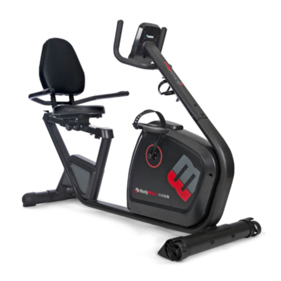
- Page 1 USER MANUAL BodyMax 60 recumbent bike...
-
Page 2: Safety Instructions
Safety Instructions... - Page 4 • To ensure the best safety of the exerciser, regularly evened out. check it on damages and worn parts. • Always wear appropriate clothing and shoes which are suitable for your work-out on the • If you pass on this exerciser to another person or if exerciser.
- Page 5 • Assemble the exerciser as per assembly instructions and be sure to only use the structural parts provided with the exerciser and designed for it. Prior to the assembly, make sure the contents of the delivery is complete by referring to the parts list of the assembly and operating instructions.
-
Page 6: Exploded Drawing
Exploded drawing... - Page 7 Part List Part no. Description Drawing no. Material Specification Q'ty Main frame 737RB-3-1000-J6 Front stabilizer 70501-6-2101-J0 Q195 D76x1.5Tx480L Bottle holder 70402-6-2074-00 120*87*3T Bolt 52605-5-0015-F0 M5*0.8*15L Handlebar set 80201-3-2400-J5 Rear stabilizer 70501-6-2107-J1 Q195 D76x1.5Tx480L Seat post 711RB-3-2200-J1 ...
- Page 8 Belt 58004-6-1046-00 410 J5 (1041 J5) Belt wheel 58008-6-1017-03 ZL102 D260*19 Round magnet 174R4-6-2574-00 Left crank 58007-6-1045-02 1015A 6 1/2"x9/16"-20UNF Right crank 58007-6-1046-02 1015A 6 1/2"x9/16"-20UNF Ball knob 52916-2-0032-BB1 Q235A+ABS D50xM16x32xD8 Upper computer cable 807E2-6-2572-00 700L Motor 73002-6-2571-00 ...
- Page 9 Foam 58015-6-1058-B0 D23*4T*500L,with hole Screw 50904-2-0010-D0 ST4x1.41x10.L Square cap 55313-2-2525-B8 25*25*13L Handle pulse 16800-6-2478-00 PE18 Rear protective cover 73600-6-4515-B0 100*93*66 Flat washer 55117-1-2315-NA Q235A D23*D17.2*1.5T Bolt 50108-5-0025-N3 M8*25 Spacer ring 80700-6-2781-00 D22.5*D17.2*6.4T Spring 58003-6-1024-N0 D2.2*D14*65L Inner tube 73600-6-1071-B0 40*80*102L Anti-loose nut 55210-1-2010-CA Q235A...
- Page 10 CHECK LIST...
- Page 11 STEP 1 1) Assemble the front stabilizer (2) onto the main frame (1) by using 4pcs curved washer (31), 2pcs spring washer (11),2pcs domed nut(12) and 2pcs allen bolt (30). 2) Assemble the rear stabilizer (6) onto the main frame (1) by using 4pcs curved washer (31), 2pcs spring washer (11),2pcs domed nut(12) and 2pcs allen bolt (30).
- Page 12 STEP 2 1) Assemble the seat (18) on the seat post(7) by using 4pcs flat washer (66) and 4pcs allen bolt (15). 2) Assemble the seat post(7) to the sliding beam(60) as the picture shown.
- Page 13 STEP 3 1) Suggest assembling this step by two persons. 2) Assemble sliding beam(60) to main frame(1) by using 2pcs flat washer(66) and 2pcs allen bolt(55) shown as fig A. and 2pcs bolt(56) ,2pcs spring washer(11),2pcs domed nut(12) and 2pcs flat washer(66) shown as fig B. Then fix the front rear cover (62) on the sliding beam shown as fig C.
- Page 14 STEP 4 1)First, lift up the handlebar post tube(10) , then connect the Upper& Lower computer cable (41 & 88), the upper handle pulse cable(46) with middle handle pulse cable (47). 2)Insert the handlebar post tube(10) on the main frame(1) and fix it by using 4pcs spring washer(11),2pcs flat washer(66),4pcs allen bolt(13),2pcs curved washer(31).
- Page 15 STEP 5 1) Assemble the left and right pedal (20L &20R) on the crank (39L & 39R). 2) Assemble the bottle holder (3) to handlebar post tube(10) with 2pcs bolt(4). 3) Assemble handlebar set (5) to the backrest supporting set (86) by using 4pcs flat washer (66), 4pcs spring washer (11), 4pcs allen bolt (13).Then connect the handle pulse cable (49) with the lower handle pulse cable (48).
- Page 16 STEP 6 1) Connect the upper handle pulse cable (46),the upper computer cable (41) to the cable of computer (8). 2)Assemble the computer (8) to the handlebar post (10) by using 4pcs bolt (87). 3)Plug the adaptor (50) to the adaptor input on the front of the bike.
-
Page 17: Display Functions
SM(SE)17 / 27 / 37 SERIES INSTRUCTION MANUAL I1248 DISPLAY FUNCTIONS ITEM DESCRIPTION TIME Count up – No preset target, Time will count up from 00:00 to maximum 99:59 with each increment is 1 minute. Count down - If training with preset Time, Time will count down from reset to 00:00. Each preset increment or decrement is 1 minute between 00:00 to 99:00. - Page 18 Start/ Stop Start or Stop workout. Recovery Test heart rate recovery status. Body fat In stop mode, press it for body fat measurement.
-
Page 19: Operation
OPERATION: POWER ON Plug in power supply, computer will power on and display all segments on LCD for 2 seconds (Drawing 1). Drawing 1 Then enter into User data setting. Use UP or DOWN (Encoder) to select U1~U4 (Drawing 2), then set SEX, AGE, HEIGHT, WEIGHT (Drawing 3) and confirm by pressing MODE / ENTER button. - Page 20 12) and press MODE / ENTER to confirm. 3. Press START/STOP keys to start workout. Use UP or DOWN (Encoder) to adjust load level. Load level display in WATT window, no adjusting for 3s, it will switch to display WATT (Drawing 13). 4.
- Page 21 Use UP or DOWN (Encoder) to set TIME. Press START/STOP key to start workout. Use UP or DOWN (Encoder) to adjust load level. Press START/STOP key to pause workout. Press RESET to reverse to main menu. Drawing 15 H.R.C. Mode 1.
- Page 22 Drawing 19 Drawing 20 BODY FAT In STOP mode, press the BODY FAT key to start body fat measurement (Drawing 21). During measuring, users have to hold both hands on the hand grips. And the LCD will display “= ” “= = ” (Drawing 22)for 8 seconds until computer finish measuring.
- Page 23 1. After 4 minutes without pedaling or pulse input, console will enter into power saving mode. Press any key may wake the console up. 2. When computer act abnormal, please plug out the adaptor and plug in again.
Need help?
Do you have a question about the RB60 and is the answer not in the manual?
Questions and answers