Table of Contents
Advertisement
Quick Links
Advertisement
Table of Contents

Related Manuals for EC Line EC-1200


Summary of Contents for EC Line EC-1200
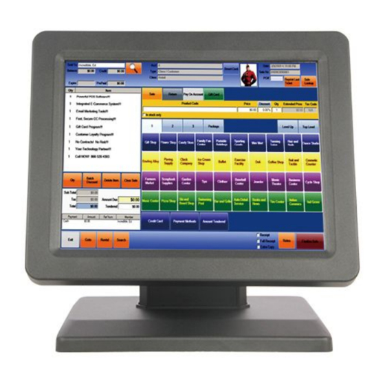
- Page 1 User Manual EC-1200 All-in-one Touch POS Terminal...
-
Page 2: Table Of Contents
1.2. Safety Information:................2 1.3 Electromagnetic compatibility statement:..........4 Chapter II: Installation Guide ................4 2.1 EC-1200 Appearances:................ 4 2.2 The front panel Function definition:............4 2.3 The rear panel I/O signs and description:......... 5 Chapter III: Instructions for use ............... 6 3.1 Motherboard BIOS settings:.............. -
Page 3: Chapter I: Overview
Chapter I: Overview Dear customer: Thank you for purchasing the EC Line All - In One touch POS devices, we are committed to continuously improve the product quality and provide better after-sales service. In order to take full advantage of our devices, we strongly recommend that you take the time to read this manual before diving into software solution. - Page 4 Tunr off the power before connecting any devices (except USB device) to the terminal. Do not attempt to open the chassis .You may be hurt by electric shock.For service,call your place of purchase. Please do not leave any item or liquid into the product, do not place any objects into the ventilation holes of this product, it may cause short-circuit of the internal components and cause a fire or electric shock.
-
Page 5: Electromagnetic Compatibility Statement
This product is in full compliance with the relevant requirements of the the People's Republic of China’s national standards of (GB/17625.1-2003) “Electromagnetic Compatibility Limits for harmonic current emission limits” for Class B products . Chapter II: Installation Guide 2.1 EC-1200 Appearances:(MSR and VFD mounting optional)... -
Page 6: The Rear Panel I/O Signs And Description
2.2 The rear panel I/O signs and description: AT the rear panel of the POS device you will see a row of the external device connection interface, such as: power outlet, the parallel connector, serial socket, USB interface, detailed as follows: POWER key: turn on/off the pos MOUSE: To connect mouse device KB: To connect the keyboard device... -
Page 7: Chapter Iii: Instructions For Use
Chapter III: Instructions for use 3.1 Motherboard BIOS settings: The POS device has a BIOS (Basic Input Output System) chip on the motherboard. Every time you start the POS devices, the system will first run the BIOS self - test program, to check the main components of the system to ensure it is working properly. - Page 8 <F7> To load the last set of values <F8> To load the safest value <F9> To load the optimal value <F10> To store settings and exit the CMOS SETUP program Step 1: Select Load Default Settings to restore optimized default settings CMOS Setup Utility- copyright (c)1985-2008 BIOS Setup Utility- copyright (c)1985-2008 Main...
- Page 9 Malfunction Advanced setup CPU Configuration IDE Configuration Configure CPU USB Configuration COM/LPT Configuration Hardware monitor Power management ↑↓→←: Move +/-:Value Enter : select F10:Save and Exit F9 : load Defaults Settings F1:General Help Esc : Exit Step 4: Select Boot Boot Configuration Bootup NumLock State Display Logo...
- Page 10 Total Memory 2048MB Configure North Step 6: Share Memory Size Bridge features Select DVMT Mode Select DVMT Mode DVMT/FIXED Memory 256MB menu unit South Bridge Configuration exit HD Audio controller Enlabled USB Function Enlabled On board LAN2 Controller Auto LAN Boot Rom Dislabled ↑↓→←: Move +/-:Value Enter : select...
-
Page 11: Touch Screen Driver Installation
3.2 Touch screen driver installation: Step 1: Open the installer directory to find the setup.exe file, double-click the installation, when apply CD-ROM installation, the path is shown below. Step 2: Double-click the installation as the following figure shows, click Next to proceed to the next installation. - Page 12 Step 3: Install In progress Step 4: Tick “install PS / 2 interface driver” and click Next to proceed installation.
- Page 13 Step 5: If the touch interface is RS232, tick “install RS232 interface driver” and click Next to proceed installation. Step 6: When choosing the calibrations, select NONE, click Next to proceed...
- Page 14 installation. Step 7: When installing USB touch, please connect the USB controller and USB cable...
- Page 15 Step 8: When there are two or more touch screen, please tick “Support multi- monitor system”. Step 9: Select the destination location to store the driver, the default path is C: \ Program Files \ eGalaxtouch; we use the default path here, click Next to proceed to installation.
- Page 16 Click Next to proceed to installation Step 10: Check the projects to create a desktop shortcut icon in the following figure After install the driver successfully, identify the USB controller card and RS232 control card as the following two figures shows.
- Page 17 Related touch function setting...
- Page 18 Touch calibration...
- Page 19 Touch device line test Touch screen setting...
- Page 20 Touch device edge correction setting Touch device hardware information display...
-
Page 21: Chapter Iv: Common Faults And Exclusion
Chapter IV: Common Faults and exclusion 1. POS device does not boot If the POS devices cannot boot after repeated pressing of the power switch (POWER) when connect to the power, the POS device power light remains off, the fan does not operate, and the BIOS beeping is not heard. - Page 22 and contacts are in good condition; (2) Check the AC 220V is stable; (3) Virus may cause this problem if the hardware parts are normal, immediately antivirus to restore the system. (4) A sudden power failure or illegal shutdown may cause this problem, press F8 to use safe mode to enter the system and debug.
- Page 23 6. The touch screen does not respond When the touch POS device does not has any reaction; 1.Remove the touch driver and then install it again Remove the touch driver and then install it again. 2. Execute the “eGalaxTouch on the desktop, check if the COM Port is normally. 3.
- Page 24 (3) Make sure the touch screen is clean without anything pasted on. (4) If the above steps do not solve the problem, please contact the products and services center in our company. 11. The cursor in the touch screen can only move in a small area or resistive touch screens are inaccurate.
- Page 25 (2) Check the BIOS USB2.0J is enabled; (3) The cable of USB external device should not be too long. Otherwise, the USB device can not be found due to the insufficient supply; (4) Re-install the USB driver (see "motherboard driver installation").
Need help?
Do you have a question about the EC-1200 and is the answer not in the manual?
Questions and answers