Advertisement
Quick Links
Programmable Precision PID Temperature Controller
Introduction
Thank you for shopping the Auber WS series temperature controller. We sincerely appreciate your
decision and trust that our controller will meet your expectations in both the quality of the result
and the value of the product. While we are delighted that you may be anxious to operate the
controller, please still spend a few minutes reading through this manual because this will serve to
enhance your experience in the months and years ahead. In particular, we urge you to read
through the safety warnings below. Although this plug-and-play controller is very easy to use, the
process involves high temperature and high wattage appliances and your safety is paramount.
•
This controller is designed only to be used with limited-power device and paring thermal
cutoff protection such as a thermostat or thermal.
•
Do not place any objects on the top of controller surface because that may prevent venting
excess heat during its operation.
•
The controller can handle a maximum current up to 12 Ampere. For 120 VAC in US or
Canada, this limits the heater power to 1440 watts. Due to its compact size and the splash
proof design for kitchen applications, the controller has a limited ability to dissipate the
heat generated by the internal solid state relay during the initial heat up. The initial full
power heat up process cannot be more than 90 minutes. If you system need take longer
time to warm up, please read Appendix 1 "Managing the heat generated by the controller"
•
Always place the temperature sensor in your controlled subject (like your smoker)
before you turn on your controller. Leaving the temperature sensor outside of your
controlled subject will form an open loop operation. If the sensor is left outside, the
controller will assume the temperature is low even if the controlled subject is already very
Quick Guide for WS-1211GPH
Version 1.3 (June, 2021)
Auber Instruments
5755 North Point Parkway, Suite 99
Alpharetta, GA 30022
770-569-8420
www.auberins.com
SAFETY WARNINGS
1
Advertisement

Related Manuals for Auber Instruments WS-1211GPH


Summary of Contents for Auber Instruments WS-1211GPH
- Page 1 Quick Guide for WS-1211GPH Programmable Precision PID Temperature Controller Version 1.3 (June, 2021) Auber Instruments 5755 North Point Parkway, Suite 99 Alpharetta, GA 30022 770-569-8420 www.auberins.com Introduction Thank you for shopping the Auber WS series temperature controller. We sincerely appreciate your decision and trust that our controller will meet your expectations in both the quality of the result and the value of the product.
-
Page 2: Description Of The Controller
Using it to control a not recommended device can be dangerous and even cause fire. Auber Instruments is not liable for damages caused by misuse of the controller. If you are not sure the controller can be used, please contact Auber Instruments before usage. -
Page 3: Connecting The Controller
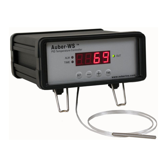
(1) Parameter Window (LED) - For displaying temperature values and controller's system parameters. (2) Output status indicator - In normal mode, this LED indicates the heater status. When it is on (lit), the heater is powered. When it is off, the heater power is off. When it is flashing, it means the heater is on and off intermittently to reduce the power output. - Page 4 a) Using two power cords and a power strip. This set up is good for the “Original”, Stainless Steel, and Digital Bradley Smoker. Figure 3. Power connection of the controller and smoker. The input of the controller is connected to the power strip by the 16 AWG power cord supplied (blue arrows).The generator is connected to the power strip by the power cord from Bradley (green arrows).
- Page 5 Fig 4. Power connection of the controller and smoker. The generator is connected to the power strip by the power cord from Bradley (green arrows). The input of the controller is connected to the female receptacle on the generator by the power jumper cord provided by the Bradley (blue arrows).
- Page 6 Figure 5. Sensor position. Left, the sensor should be placed close to the food but high enough so that it does not touch the food. Right, hold the sensor in place by a piece of tape. For the “Original” and Stainless Steel Bradley smoker, the Temperature Heat Control Switch on the smoker tower should be slide to the Hi position (Most right).
- Page 7 programming the necessary cooking steps, you can finish programming by pressing the SET repeatedly until the display passes t-6 and displays the current temperature. You can also leave the controller alone. The display will return to the normal display mode if no key is pressed within 15 seconds.
- Page 8 press “Time” key, the controller will show “P 40” with the Time Indicator lit. At normal operating mode, press the “Time” key (item 6 in Figure 1) once to toggle the LED window between the current temperature and the total time (in minutes) since the controller was powered up.
- Page 9 Anti-short Cycle 0-200 Delay (only for cooling mode) The third group of parameters is about the alarm setting with access code 188. Table 5 shows a list of the parameters, their range and initial set value when left the factory. Table 5.
-
Page 10: Single-Step Mode
To recall a recipe, press and hold SET key for 3 seconds until the Parameter Window displays “LoCK”. Release the SET. The display will show “0”. Use “+” and “-” keys to adjust the display to 1 and press SET. The display will show “rC” for a second and then the value “End”. If press SET key now, you will exit this mode without overwriting any existing programs. - Page 11 C-2= 290, F-2=160; C-3=130, F-3=30.0. You can leave the rest of steps as their default values. To store in program to recipe b1, long press SET key, set LoCK=2, choose b1, and press SET again to confirm and exit. Now the controller is back to the normal operating mode. It will run on this current program, which has just been saved as recipe b1.
-
Page 12: Factory Reset Function
Copyright © 2021 Auber Instruments Inc. All rights reserved. No part of this datasheet shall be copied, reproduced, or transmitted in any way without the prior, written consent of Auber Instruments. Auber Instruments retains the exclusive rights to all information included in this document.
Need help?
Do you have a question about the WS-1211GPH and is the answer not in the manual?
Questions and answers