Advertisement
Quick Links
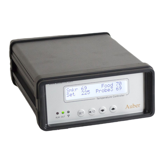
Programmable PID Temperature Controller
Introduction
Thank you for purchasing the Auber WS series temperature controller. We sincerely
appreciate your decision and trust that our machine will meet your expectations in both
the quality of the result and the value of our product. While we are delighted that you
may be anxious to operate the controller for your project, a few minutes of your time
reading through this manual will only serve to enhance your experience in the months
and years ahead. In particular, we urge you to read through the safety warnings below.
Although this plug-and-play controller is very easy to operate, the process involves high
temperature and high wattage appliances and your safety is paramount.
• This controller is designed only to be used with devices that have limited power
and their own thermal cut off protection, such as a thermostat or thermal fuse in
case of controller failure.
• Do not place any objects on the top of controller surface which is used to vent
excess heat during its operation.
• The maximum electric current this controller can handle is 15 ampere. For 120
volt AC in US and Canada, this limits the heater power to 1800 watts.
• Always place the sensor in the controlled subject when the controller is on.
Before turning on the controller, please make sure the sensor is placed inside the
container to be controlled. Leaving the sensor outside of the solution will form an
open loop operation. If the sensor is left outside, controller will assume the
temperature is low even if the controlled subject is already very hot. The
controller will provide full power to the heater. It will not only overheat the
controller, but also damage your appliance, and even cause a fire.
• This controller is designed to control the devices recommended by Auber
No part of this manual shall be copied, reproduced, or transmitted in any way without the prior, written consent of Auber Instruments.
Auber Instruments retains the exclusive rights to all information included in this document.
Operation Instruction Manual
WSD-1500H-W
Version 2.0 (Dec, 2019)
Auber Instruments
5755 North Point Parkway, Suite 99
Alpharetta, GA 30022
770-569-8420
www.auberins.com
SAFETY WARNINGS
Copyright © 2019 Auber Instruments Inc. All rights reserved.
Advertisement

Related Manuals for Auber Instruments WSD-1500H-W


Summary of Contents for Auber Instruments WSD-1500H-W
- Page 1 Copyright © 2019 Auber Instruments Inc. All rights reserved. No part of this manual shall be copied, reproduced, or transmitted in any way without the prior, written consent of Auber Instruments. Auber Instruments retains the exclusive rights to all information included in this document.
-
Page 2: Specifications
Instruments only. Using it to control a not recommended device can be dangerous and cause fire. Auber Instruments is not liable for damages caused by misuse of the controller. If you are not sure the controller can be used, please contact Auber Instruments before use. - Page 3 Operating Instructions 1. Description of the controller Figure 1. Front Panel. 1) LCD display window – During normal display mode, it will display temperature readings from all probes and set temperature for cabinet. When high or low limit alarm is triggered, this display will show alarm notification. In time checking mode, it will display time/step information.
- Page 4 module is ready for configuration. Slow flashing: Wi-Fi module is initializing its connection to the router. Off: no Wi-Fi connection. 5) SET Key – Press momentarily to enter the cooking profile settings. Press and hold about 2 seconds to enter parameter settings. This key can also be used to confirm the change of setting.
- Page 5 internal temperature measurement (Probe 2). It needs to be plugged to the bottom sensor jack at the back of the controller. The tips of the probes are dropped into the damper hole. Place a piece of tape on the top of the smoker tower to hold them in place.
- Page 6 1) Connection for Bradley Original Smoker, with control of the smoker generator. a) Connecting the controller to the power outlet, you should use the power cord that came with the Bradley Smoker for connecting the smoker generator to the power outlet. b) Connecting the controller to the smoker generator.
- Page 7 c) Connecting the controller output to the Bradley Smoker Tower with the power cord that came with the Auber Controller To Power Outlet Cable B Cable A Smoke Smoker Tower Auber Generator Controller Probe 2: Probe 1: Internal Temp Cabinet Temp Figure 5.
- Page 8 Figure 7. Connection between the controller and smoker 2) Connection for Bradley Digital Smoker. For the Bradley Digital Smoker, both controller and smoker generator should be connected directly to the wall outlet. Connect the controller output with the smoker tower. To Power Outlet To Power Outlet Cable B...
-
Page 9: Normal Display Mode
3. Display modes Figure 9. Switching between different display modes Four display modes are available: 1) Normal display, 2) Time Checking, 3) Cooking Profile and 4) Parameter setting. When you turn on the controller, it will show the initializing display for several seconds. it will display controller’s name and firmware version during this period. - Page 10 Figure 11-2. Information displayed in normal display mode (when probe 3 is disabled in the setting, note 16 in section 7.2) 3.2 Time checking mode To check current running status (status check mode), press Timer Key momentarily. Press Time Key again to display more information, or return back to normal display mode.
-
Page 11: Parameter Setting Mode
after you recently powered up the controller (top), and current power output percentage. Press timer key again to return to normal display mode. Figure 14. Time checking mode when single step mode. Display #3 (if single step mode): Press timer key to display the total running time after you recently powered up the controller (top), and current power output percentage. - Page 12 4.1 Set the Cooking Profile The controller’s cooking profile can be either set to multi-step mode (default) or single- step mode. In the multi-step mode, up to 6 steps can be programmed. Each step has its own set temperature for cabinet probe (Probe 1), and its step-ending criterion. A cooking step can either end by timer or by food internal temperature (Probe 2).
- Page 13 the “X-Ending” are set to time, the controller can operate with only the cabinet probe (Probe 1) plugged in. Note: user can also use Aubersmart app to view and change both time and food temperature of each step. Cooking Profile Example Table 1.
- Page 14 to exit the menu. Or, you can use ▲ or ▼ key to go to “Back”, and press SET key to exit. The display can also return to the normal display mode if no key is pressed in about 15 seconds. Smkr 137 00000000000000000000 Food 122...
- Page 15 “Step: 1” and the current target cabinet temperature in the top line. A curser “>” will be shown on the left indicating which line will be selected. Press SET key once, the current set temperature should start blinking. Use ▲ and ▼ keys to change the set temperature.
-
Page 16: Multi-Step Mode
00000000000000000000 Smkr 137 Food 122 Set 250 Probe3 670 00000000000000000000 SE T SE T 00000000000000000000 >Prog S tatus Stop Prog S tatus Stop Prog S tatus Start 00000000000000000000 Step 1 SmkrTemp 250 SE T SE T 00000000000000000000 >Step 1 SmkrTemp 250 Step 1 SmkrTemp 250 Step 1 SmkrTemp 120 00000000000000000000... - Page 17 7.1 Control Configurations Parameters related control configurations during the smoking process are listed under “Control Config” menu. Error! Reference source not found. shows the list of these parameters, their range and initial set value when left the factory. The flow chart in Figure 21 shows the operations of accessing and adjusting the parameters in “Control Config”.
- Page 18 00000000000000000000 > Cont ro l Sett i ng System Con f i g 00000000000000000000 SE T SE T >Smkr Hi A l arm 00000000000000000000 Smkr Hi A l arm Smkr Hi A l arm 00000000000000000000 Smkr Lo A l arm SE T SE T >...
- Page 19 the Smkr Lo Alarm, you can set it to a small number, such as 0°F (default). Figure 23. The LCD display when Smkr Lo Alarm is triggered. Note 3. Food Hi Alarm: This is the high temperature alarm for the food internal probe (Probe 2).
- Page 20 Note 5. Relay Action: This is smoke generator relay setting. This parameter determines which steps to turn on smoke generator output. Its configuration range is from 0 to 63. It is determined by the following formula: Relay Action = A * 1 + B * 2 + C * 4 + D * 8 + E * 16 + F * 32; If A = 0, smoke generator output is OFF at Step 1.
- Page 21 cabinet temperature and set temperature stays constant, the output will be doubled after 1000 seconds. Integral action is used to eliminate temperature offset. Larger number means slower action. E.g. assuming the difference between the measured and set temperature is 2 degrees and remain unchanged, the output will increase continuously with time until it reaches 100%.
-
Page 22: System Configurations
Note 11.1 Save a recipe After a recipe has been entered, the user can save this current program as a recipe for future use. Go to Parameter Setting mode by holding the SET key, and then go to “Control Setting” menu, find parameter “Save Recipe”, press SET key again so you can change its value. - Page 23 Table 3. Parameters in System Config menu. Name Description Range Initial Note Program Mode Multi-Step Program ON, OFF Output Hi Limit Output High Limit % 0 - 100 Temp Unit Temp Unit (° C or ° F) C, F Smkr Probe Offset Cabinet Probe (Probe 1) Offset -9 - 99 Fd Probe Offset...
- Page 24 PID algorithm determines 50% output value, the actual power output will be 250 watts. This function can be used in two situations. 1) When you have a very powerful heater and using a very small pot of water to cook at very low temperature, for example, a 1400 watts heater with a one litter (1 qt) pot of water at 130°F.
- Page 25 Note 18. Backlight Level: LCD backlight level setting. The higher the value, the brighter the LCD display. 0 is lowest brightness. 10 is highest brightness. Note 19. Dwell Time: Data Logging Sampling Interval. This parameter controls the temperature sampling interval, which will be used for data export function and plot display on Aubersmart app.
- Page 26 your local power line frequency. 8. Important consideration for better control results. The following is a list of things that could affect the result of temperature control. a) The smoker and controller location. The smoker should not be placed directly in the sun.
- Page 27 system or run the auto-tune again. For detailed information on how to tune the controller, please read the section 10 for tuning the controller. 10. Auto-Tune This section can be ignored if you are using the controller to control the Bradley Smoker because the controller already set for it.
- Page 28 Figure 28. Auto-tune Before using the auto-tune function, you must set the cooking equipment up in the exact configuration it will be used. For example, to tune a rice cooker, place the sensor in the room temperature pot filled with water and plug the cooker into the controller. If the cooker has its own thermostat or power control, turn both as high as they’ll go.
- Page 29 Copyright © 2019 Auber Instruments Inc. All rights reserved. No part of this manual shall be copied, reproduced, or transmitted in any way without the prior, written consent of Auber Instruments. Auber Instruments retains the exclusive rights to all information included in this document.
-
Page 30: Warranty
If your appliance fails to operate properly, please contact Auber’s customer support. If the appliance is found by Auber Instruments to be defective in material or workmanship, Auber Instruments will repair or replace it free of charge. A dated proof of purchase may be required. - Page 31 Appendix 1 Managing the heat generated by the controller The heat dissipation of the controller is directly related to the electric current drawing power of the heater. If your cooker consumes less than 10 ampere of current or your pot is less than 5 gal (19 liters), you do not need to worry about the heat generated by the controller.
- Page 32 have a pot that is bigger than 10 gallon and the heater is drawing 18 A, and you need to raise the temperature by 108 °F, you better use one of the methods mentioned below to reduce the heat in the controller. Otherwise, you might damage the controller. Please note that when the ambient temperature is hot, as it is often the case in some commercial kitchens, the temperature of the controller will get hotter.
Need help?
Do you have a question about the WSD-1500H-W and is the answer not in the manual?
Questions and answers