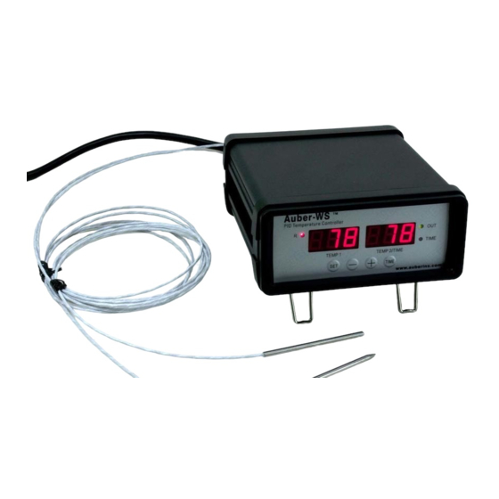
Auber Instruments WS Series Operation & Instruction Manual
Programmable pid temperature controller with dual probe
Hide thumbs
Also See for WS Series:
- Operation & instruction manual (28 pages) ,
- Quick manual (15 pages) ,
- Operation & instruction manual (22 pages)
Advertisement
Quick Links
Programmable PID Temperature Controller with Dual Probe
Introduction
Thank you for purchasing the Auber WS series temperature controller. We sincerely
appreciate your decision and trust that our machine will meet your expectations in both
the quality of the result and the value of our product. While we are delighted that you may
be anxious to operate the controller for your project, a few minutes of your time reading
through this manual will only serve to enhance your experience in the months and years
ahead. In particular, we urge you to read through the safety warnings below. Although
this plug-and-play controller is very easy to operate, the process involves high
temperature and high wattage appliances and your safety is paramount.
• This controller is designed only to be used with devices that have limited power
and their own thermal cut off protection, such as a thermostat or thermal fuse in
case of controller failure.
• Do not place any objects on the top of the controller surface as it is used to vent
excess heat during its operation.
• The maximum electric current this controller can handle is 13 ampere. For 120
volt AC in US and Canada, this limits the heater power to 1450 watts.
• Always place the sensor in the controlled subject when the controller is on. Before
turning on the controller, please make sure the sensor is placed inside the
container to be controlled. Leaving the sensor outside of the solution will form an
open loop operation, and the controller will assume the temperature is low even if
the controlled subject is already very hot. The controller will provide full power to
the heater which will not only overheat the controller, but also damage your
Patent pending
*
Operation Instruction Manual
WSD-1200GPH
Version 1.9 (Sep, 2017)
Auber Instruments
5755 North Point Parkway, Suite 99
Alpharetta, GA 30022
770-569-8420
www.auberins.com
SAFETY WARNINGS
1
*
Advertisement

Related Manuals for Auber Instruments WS Series


Summary of Contents for Auber Instruments WS Series
- Page 1 Introduction Thank you for purchasing the Auber WS series temperature controller. We sincerely appreciate your decision and trust that our machine will meet your expectations in both the quality of the result and the value of our product. While we are delighted that you may...
-
Page 2: Specifications
• This controller is designed to control the devices recommended by Auber Instruments only. Using it to control a non-recommended device can be dangerous and cause fire. Auber Instruments is not liable for damages caused by misuse of the controller. If you are not sure the controller can be used, please contact Auber Instruments before use. - Page 3 connector off the cord to a power strip outlet that meets the local standards for the output. For the input, the controller has standard IEC 320 C13/14 socket. Users can use a computer power cord that meets the local standard to power it. Operating Instructions 1.
- Page 4 5) Timer status indicator - When lit, right window shows the time passed since power up. When it is off, right window shows the current temperature detected by the probe 2. 6) SET Key - For showing current temperature settings, entering parameters setting mode and confirming various actions taken.
- Page 5 2. Connecting and operating the controller Install the sensor. (Note: If you ordered wall mount sensor instead of free hanging sensor, please see the separate instruction in the CD for its installation) The controller is supplied with two probes. The one with the short tip is for measuring the cabinet temperature.
- Page 6 Figure 3.1 Power Cable wiring for Original Bradley Smoker Cable A: Power cable for Smoker Tower, C14 plug Cable B: Power cable for smoke generator, NEMA5-15P plug 1) Connection for Bradley Original Smoker, with control of the smoker generator. a) Connecting the controller to the power outlet, you should use the power cord that came with the Bradley Smoker for connecting the smoker generator to the power outlet.
- Page 7 c) Connecting the controller output to the Bradley Smoker Tower with the power cord that came with the Auber Controller To Power Outlet Cable B Cable A Smoke Smoker Tower Auber Generator Controller Probe 2: Probe 1: Internal Temp Cabinet Temp Figure 5.
- Page 8 Figure 7. Connection between the controller and smoker 2) Connection for Bradley Digital Smoker. For the Bradley Digital Smoker, both controller and smoker generator should be connected directly to the wall outlet. Connect the controller output with the smoker tower. To Power Outlet To Power Outlet Cable B...
- Page 9 3. Programming the smoking temperature profile A total of 6 steps can be programmed with this controller. Each step contains the set temperature (C-X) and an ending criteria setting (E-X), where “X” is the step number (e.g. Step 4 temperature is represented by C-4 and step 4 ending criterion is represented by E-4).
- Page 10 hours, waiting for you to pick up the food. If you set C-3=0 and t-3=0, when meat internal temperature reaches 160 °F, the controller will shut off the heater, flashing END on both windows, and turn on the beeping alarm to notify you that cooking is finished. Table 1.
- Page 11 a) The smoker and controller location. The smoker should not be placed directly in the sun. Direct sun light can heat the smoker to above 140 °F in the summer time, making controlling the temperature at 140 °F impossible. This is especially the problem for the Bradley Original Smoker because of its black color.
- Page 12 Table 2 List of control parameters and its initial settings under code 166 Symbol Display Description Range Initial Proportional band 0-600 Integral constant (second) 0-900 Derivative constant (second) 0-300 Auto-tune 0=off 1=on t Cycle rate (second) 1-100 Smoker generator on step 1 Smoker generator on step 2 Details about each parameter •...
- Page 13 amount of change. This will allow the controller to act sooner. It will turn the heater to full power before the temperature drops too much • AT. Auto-tune function. Set AT to 1 then exit the menu. The display will start to flash alternately between AT and the current water bath temperature, which indicates auto-tuning is in progress.
- Page 14 Figure 9. Code 166 Parameter setup flow chart Press and hold SET key for 4 seconds until LED displays “LCK” on the left window. Then release the SET key. The display on the right window will show “0”. To get into parameters setting mode, you need to key in the pass code.
- Page 15 Details about each parameter. • SC, calibration offset. The parameter is used to make the input offset to compensate for the error produced by sensor. e.g. if the temperature displays of left window is 2.0 °C in ice water mixture, set SC1= - 2.0 will make the display to shown 0.0 degree.
- Page 16 Figure 10. Code 155 Parameter setup flow chart Press and hold SET key for 4 second until the left window displays “LCK”. Release the SET. The right window will show “0”. Use “+” and “-” keys to adjust the display to 155 (another pass code) and press SET.
- Page 17 c) AH2 is the high limit alarm for probe 2. If AH2 is set to 190, this alarm will be on at 191 and off at 190. When this alarm is on, the right window will flash between AH2 and the current temperature.
- Page 18 8. Auto-Tune This section can be ignored if you are using the controller to control the Bradley Smoker because the controller is already set for it. The controller's most powerful feature is its ability to regulate virtually any cooker with stable temperature control.
- Page 19 Before using the auto-tune function, you must set the cooking equipment up in the exact configuration it will be used. For example, to tune a rice cooker, place the sensor in the pot filled with water at room temperature and plug the cooker into the controller. If the cooker has its own thermostat or power control, turn both as high as they’ll go.
- Page 20 Use “+” or “-” key to select the name of recipe to which you want to store the program. If you press “+” (or “-” key) repeatedly, you will see “End”, “b1”, “b2”, “C1”, “C2”, “F1”, “F2”, “P1”, “P2” one by one. Press the SET key again to store your current program under the selected recipe name.
-
Page 21: Single-Step Mode
Figure 11. Flow chart of recalling a recipe. 10. Single-step mode In this mode, the controller will hold temperature at one set value (C-1) continuously as long as the controller is powered on. Even if the controller is powered off and turned on again, it will resume working in this mode. - Page 22 Figure 12. Single-step mode flow chart. In single-step mode, the save and recall function (Section 9) can still work. But the change can only be applied to C-1, i.e., you can only store your current set temperature to the C-1 in a selected recipe, or recall the C-1 temperature from a selected recipe to the current set temperature.
- Page 23 Before you input your set temperature, check the PrG = off (accessed by LCK code “3”). Press SET key once, and then set C-1=150, press set again to confirm and exit. The controller will go back to the normal operating mode and start running on this single-step program.
- Page 24 LED display “LCK” on the left window, and then release the SET key. The display on the right window will show “0”. Use “+” key to adjust the number to 666 and press SET key again to confirm. The left display will show as “lnt” and right display will show as “off”. Press “+”...
-
Page 25: Warranty
Alpharetta, GA 30022 USA If the appliance is found by Auber Instruments to be defective in material or workmanship, Auber Instruments will repair or replace it free of charge. A dated proof of purchase may be required. The liability of Auber Instruments is limited solely to the cost of the repair or replacement of the unit at our discretion. - Page 26 Copyright 2007-2017, Auber Instruments All Rights Reserved. No part of this manual shall be copied, reproduced, or transmitted in any way without the prior, written consent of Auber Instruments. Auber Instruments retains the exclusive rights to all information included in this document.
- Page 27 Appendix 1 Managing the heat generated by the controller The heat dissipation of the controller is directly related to the electric current drawing power of the heater. If your cooker consumes less than 10 ampere of current or your pot is less than 5 gal (19 liters), you do not need to worry about the heat generated by the controller.
- Page 28 In addition to these solutions, following information will also help you to manage the heat. Place the controller in the right place. The SSR of Auber WS series controller is mounted in the bottom of chassis. The chassis is made of 3 mm thick aluminum for good heat dissipation.
Need help?
Do you have a question about the WS Series and is the answer not in the manual?
Questions and answers