Advertisement
Quick Links
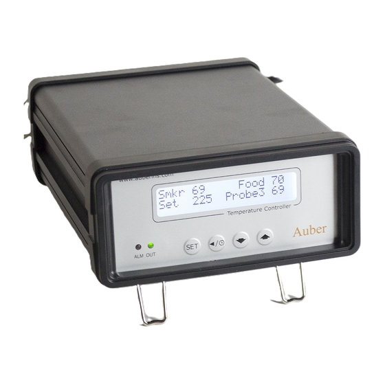
Programmable PID Temperature Controller
Introduction
Thank you for purchasing the Auber WS series temperature controller. We sincerely
appreciate your choice and trust that our product will meet your quality and value
expectations. At this moment, you may be anxious to operate your own electric smoke
controller, but a few minutes of your time reading through this manual will only serve to
enhance your purchase experience. In particular, we urge you to read through the
safety warnings below. Although this plug-and-play controller is rather simple to
operate, the process involves high temperature and high wattage appliances, and your
safety is our number one priority.
• This controller is designed only to be used with devices that have limited power
and thermal cut off protection, such as thermostats or thermal fuses in case of
controller failure.
• Do not place anything on the top of controller surface, which is used to vent
excess heat during its operation.
• The maximum electric current this controller can handle is 15 Amperes. For 120
Volts AC in US and Canada, this limits the heater power to 1800 Watts.
• Always place the sensor in the controlled subject when the controller is on. Before
turning on the controller, please make sure the sensor is placed inside the
container. Leaving the sensor outside of the solution will form an open loop
operation. If the sensor is left outside, the controller will assume the temperature
is low even if the controlled subject is already very hot. The controller will provide
full power to the heater. It will not only overheat the controller, but also damage
your appliance, and possibly even cause a fire.
No part of this manual shall be copied, reproduced, or transmitted in any way without the prior, written consent of Auber Instruments.
Auber Instruments retains the exclusive rights to all information included in this document.
Operation Instruction Manual
WST-1510H / AW-WST1510H-W
Version 1.3 (Nov, 2021)
Auber Instruments
5755 North Point Parkway, Suite 99
Alpharetta, GA 30022
www.auberins.com
SAFETY WARNINGS
Copyright © 2021 Auber Instruments Inc. All rights reserved.
Advertisement

Related Manuals for Auber Instruments WST-1510H


Summary of Contents for Auber Instruments WST-1510H
- Page 1 Copyright © 2021 Auber Instruments Inc. All rights reserved. No part of this manual shall be copied, reproduced, or transmitted in any way without the prior, written consent of Auber Instruments. Auber Instruments retains the exclusive rights to all information included in this document.
-
Page 2: Specifications
Instruments only. Using it to control a not recommended device can be dangerous and potentially cause fire. Auber Instruments is not liable for damages caused by misuse of the controller. If you are not sure the controller can be used, please contact Auber Instruments before use. - Page 3 Operating Instructions 1. Description of the controller Figure 1. Front Panel. 1) LCD display window – During normal display mode, the screen will display temperature readings from all probes and set temperature of the smoke cabinet. When either the high or low limit alarm is triggered, this display will show alarm notification.
- Page 4 internet. Fast flashing: Wi-Fi module is ready for configuration. Slow flashing: Wi-Fi module is initializing its connection to the router. Off: no Wi-Fi connection. 5) SET Key – Press momentarily to enter the cooking profile settings. Press and hold about 2 seconds to enter parameter settings. This key can also be used to confirm the change of setting.
- Page 5 is for the meat internal temperature measurement (Probe 2). It needs to be plugged to the bottom sensor jack at the back of the controller. The tips of the probes are dropped into the damper hole. Place a piece of tape on the top of the smoker tower to hold them in place.
- Page 6 Figure 3.1 Power Cable wiring for Original Bradley Smoker Cable A: Power cable for Smoker Tower, C14 plug Cable B: Power cable for smoke generator, NEMA5-15P plug 1) Connection for Bradley Original Smoker, with control of the smoker generator. a) When powering your controller, you should use the power cord that came with the Bradley Smoker.
- Page 7 c) Connect the controller output to the Bradley Smoker Tower with the power cord that came with the Auber controller. To Power Outlet Cable B Cable A Smoke Smoker Tower Auber Generator Controller Probe 2: Probe 1: Internal Temp Cabinet Temp Figure 5.
- Page 8 Figure 7. Connection between the controller and smoker 2) Connection for Bradley Digital Smoker. For the Bradley Digital Smoker, both the controller and smoker generator should be connected directly to the wall outlet. In addition, the controller output must be connected with the smoke tower.
-
Page 9: Display Modes
3) WIFI Setup (for WiFi model only) Please download latest AuberWIFI app from iOS Appstore or Android Google Play, and process the setup through the app. For support, please see the Help Center on auberins.com and find for “App with WiFi Setup”. To reset the WIFI function on the controller, press and hold both the SET key and the timer key (left two keys) at same time for about 3s. -
Page 10: Normal Display Mode
3.1 Normal display mode Figure 11-1. Information displayed in normal display mode (Default) Figure 11-2. Information displayed in normal display mode (when probe 3 is disabled in the setting, note 16 in section 7.2) 3.2 Time checking mode To check current running status (status check mode), press the timer key momentarily. Press time key again to display more information or to return back to normal display mode. - Page 11 Figure 13. Time checking mode when current step is ended by food temperature (multi-step mode). Display #2 (if current step is ended by food temperature): In normal mode, press the timer key momentarily to display the elapsed time for current step (top) and food probe ending temperature (bottom).
- Page 12 3.4 Parameter setting mode Figure 16. Access the menu of parameter setting mode using SET key. Press and hold the SET key for about 2s to enter parameter setting mode. For details, please check section 5. 4. Operation All cooking profile settings and control parameters can both be accessed from the device and AuberWIFI app (for WIFI model only).
- Page 13 cooking step depending on the X-Ending setting (either X-Time or X-Fd Temp). Figure 17. For each cooking step, set the target cabinet temperature, ending criterion, and timer or target food temperature. If “X-Ending” of a certain step is set to “Fd Temp” while the food probe (Probe 2) is not plugged in, this step will never end.
- Page 14 A flow chart of how to enter the cooking profile is shown in Figure 18. To start, program the cooking profile. Press the SET key shortly to enter the Cooking Profile Programming mode. The top line in the display shows the step number “Step: 1” and the current target of cabinet temperature “SmkrTemp 250”.
- Page 15 Figure 18. How to enter a cooking profile. The example program in table 1 is used in this flow chart as a demo. 4.1.2 Single-Step Mode In single-step mode, you can only access and change the target cabinet temperature of Step 1 from the device.
- Page 16 Prog Status on the left top and the current step number or stopped status on the right top. Press the SET button again, then user can change its options to start/stop the program or jump steps. Press the SET button again to confirm the change. See option definition and flow chart below.
-
Page 17: Multi-Step Mode
Smkr 137 00000000000000000000 Food 122 Set 250 Probe3 270 00000000000000000000 Press & Hold SE T > System Con f i g 00000000000000000000 00000000000000000000 Back SE T Multi-step Mode Single-step Mode SE T 00000000000000000000 >Program Mode Program Mode Program Mode 00000000000000000000 Output Hi L im i t 100 SE T 00000000000000000000... - Page 18 Table 2. Parameters in Control Config menu. Name Description Range Initial Note Cabinet Probe High Alarm Smkr Hi Alarm 0 - 750 (Probe 1) Cabinet Probe Low Alarm Smkr Lo Alarm 0 - 750 (Probe 1) Food Probe High Alarm Food Hi Alarm 0 - 650 (Probe 2)
- Page 19 example, if Smkr Lo Alarm is set to 180°F. The buzzer will go off when the cabinet temperature drops to 179°F; it will stop when temperature rise above 181°F. The Smkr Lo Alarm is suppressed when the controller is just powered up. It will be activated when the cabinet temperature has reached the target cabinet temperature.
- Page 20 Figure 25. The LCD display when Probe3 Hi Alarm is triggered. Note 5. Relay Action (for Multi-Step Mode Only*): This is the smoke generator output setting. This parameter determines which steps to initiate on the smoke generator output. Its configuration range is from 0 to 63, determined by the following formula: Relay Action = A * 1 + B * 2 + C * 4 + D * 8 + E * 16 + F * 32;...
- Page 21 When the temperature is 5 degree below the set point, the output is 71%. When the temperature is equal to the setting, the controller will have 0% output (assuming integral and derivative functions are turned off). This constant also affects both integral and derivative action.
- Page 22 parameters are set and are used for the system. The new parameters will store in the memory even the power is off. To cancel the current auto-tuning process, please set this parameter to OFF. For more information about auto-tune, please see section 10. Note 11.
-
Page 23: System Configurations
important to you. Go to the Parameter Setting mode by holding the SET key and then go to “Control Setting” menu, find parameter “Save Recipe”, and press SET key again so you can change its value. If you press ▲ or ▼ key repeatedly, you will see “Back”, “B1”, “B2”, “C1”, “C2”, “F1”, “F2”... - Page 24 00000000000000000000 > System Con f i g 00000000000000000000 Back SE T SE T >Program Mode 00000000000000000000 Program Mode Program Mode 00000000000000000000 Output Hi L im i t 100 SE T SE T 00000000000000000000 >Output H i L im i t 100 Output H i L im i t 100 Output H i L im i t 95 Temp Unit...
- Page 25 2) When the cooker consumes more power than controller can handle, for example, if you have a 12A, 120V AC heater and your cooker contains more than 38 Liter (10 Gallon) of water. It might take more than 90 minutes of full power heating for controller to heat up the pot.
- Page 26 output will be disabled until the probe 3 alarm is cleared. Note 19. Step End Alarm: Step ending alarm setting. When Step End Alarm is set to “ON”, the buzzer will beep 4 times when each step is finished. It is useful to notify the user the cooking step is finished.
- Page 27 Hertz interferences and “B” for 60 Hertz interferences. If you encounter fast fluctuating temperature reading issue, you can change this setting to “A” or “B” manually based on your local power line frequency. Note 24. Password (for WIFI model only): Device access password. This parameter is used to lock the access to parameter settings on AuberWIFI app.
- Page 28 shelves were empty, the temperature inside the smoker tower is fairly uniform except the back half of the lowest shelf that is close to the heater. Users should avoid placing the sensor too close to the heater because it does not represent the temperature of the rest area.
- Page 29 When Should the Controller be Tuned? If the PID parameters we provided are not working for your liking, you can use the auto-tuning function to let the controller to determine the PID parameters automatically. Auto-tuning function (it’s often known as self-tuning) can automatically optimize the PID parameters based on your system.
- Page 30 Copyright © 2021 Auber Instruments Inc. All rights reserved. No part of this manual shall be copied, reproduced, or transmitted in any way without the prior, written consent of Auber Instruments. Auber Instruments retains the exclusive rights to all information included in this document.
-
Page 31: Warranty
Auber Instruments to be defective in material or workmanship, Auber Instruments will repair or replace it free of charge. A dated proof of purchase may be required. An unique RMA number will be assigned for this return/repair. - Page 32 Appendix 1 Managing the heat generated by the controller The heat dissipation of the controller is directly related to the electric current drawing power of the heater. If your cooker consumes less than 12 amperes of current or your pot is less than 5 gal (19 liters), you do not need to worry about the heat generated by the controller.
- Page 33 Copyright © 2021 Auber Instruments Inc. All rights reserved. No part of this manual shall be copied, reproduced, or transmitted in any way without the prior, written consent of Auber Instruments. Auber Instruments retains the exclusive rights to all information included in this document.
Need help?
Do you have a question about the WST-1510H and is the answer not in the manual?
Questions and answers