Advertisement
Quick Links
www.ti.com
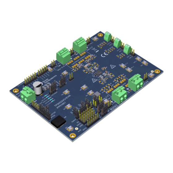
EVM User's Guide: TPS65224Q1EVM
TPS6522x Evaluation Module
Description
The TPS6522x power management integrated circuit
(PMIC) family is extremely flexible providing multiple
outputs in a single package helping to optimize space
usage in a system. TPS6522x PMIC includes four
step-down converters (buck regulators) and three
low-dropout (LDO) regulators. Two of these buck
regulators can be used in multi-phase mode to
provide up to 10 A source. The PMIC also has a
built-in analog-to-digital converter (ADC) which can
be used to monitor the core temperature or external
signals which helps to reduce the required system
space further. The TPS6522x evaluation module
(EVM) is both an evaluation and development tool.
With the EVM both device level and system level
configurability is available through an easy to use
graphical user interface (GUI) tool.
Get Started
1. Order the EVM here.
SLVUCU6 – NOVEMBER 2023
Submit Document Feedback
2. Download the GUI for configuration and
evaluation.
3. Download the supporting documents here.
4. Get additional material in
design
Features
•
Input voltage range from 2.8 V to 5.5 V
•
Evaluation module can be powered with a bench
power supply or USB-C
•
On-board MSP432 to communicate with PMIC
using the GUI via USB-C cable
•
Board can be reworked to support other TPS6522x
devices
Applications
•
Automotive infotainment and digital cluster,
navigation systems, telematics, body electronics
and lighting
•
Advanced driver assistance system (ADAS)
•
Industrial control and automation
Copyright © 2023 Texas Instruments Incorporated
functional safety
secure resources.
TPS6522x Evaluation Module
Description
and
1
Advertisement

Related Manuals for Texas Instruments TPS65224Q1EVM


Summary of Contents for Texas Instruments TPS65224Q1EVM
- Page 1 Get Started • Advanced driver assistance system (ADAS) • Industrial control and automation 1. Order the EVM here. SLVUCU6 – NOVEMBER 2023 TPS6522x Evaluation Module Submit Document Feedback Copyright © 2023 Texas Instruments Incorporated...
-
Page 2: Kit Contents
1 Evaluation Module Overview 1.1 Introduction The TPS65224Q1EVM evaluation module is designed to demonstrate the capabilities of the TPS6522x device family, both automotive and industrial. The EVM can be used to load all the outputs at the maximum current levels and configure different output capacitor combinations for evaluating the performance of the device. The multiple test points in the EVM make measuring voltage levels for all the rails and test the functionality of the device easier. -
Page 3: Device Information
Figure 1-1. Typical AM62P PDN Using TPS6522430-Q1 1.4 Device Information The TPS65224Q1EVM has TPS6522430RAHRQ1 PMIC populated by default with the configuration shown in Section 1.3. The EVM is designed to demonstrate and validate the functionality of this device. The EVM also has MSP432E401Y microcontroller to enable communication with the GUI. - Page 4 EN/PB/VSENSE pin by placing jumper in J33 to power up the rails. Please refer to Table 2-6 for the correct jumper connection. Figure 2-1. EVM with Default Jumper Options Shown in Red (Top View) TPS6522x Evaluation Module SLVUCU6 – NOVEMBER 2023 Submit Document Feedback Copyright © 2023 Texas Instruments Incorporated...
-
Page 5: Test Point Descriptions
J16, J17, J18 LDO1, LDO2, LDO3 as voltage monitor for an external rail. Note On J35 the left pin is GND_S and right pin is VCCA_S. SLVUCU6 – NOVEMBER 2023 TPS6522x Evaluation Module Submit Document Feedback Copyright © 2023 Texas Instruments Incorporated... - Page 6 Trigger signal for trigger mode watchdog. GPIO2 of the PMIC must be in the Closed alternative function to support the trigger mode watchdog signal. TPS6522x Evaluation Module SLVUCU6 – NOVEMBER 2023 Submit Document Feedback Copyright © 2023 Texas Instruments Incorporated...
- Page 7 GPIO3 is connected to push button S3. A resistor pulls the pin high when not pressed. When GPIO3, PB pressed, EN/PB/VSENSE is connected to ground. SLVUCU6 – NOVEMBER 2023 TPS6522x Evaluation Module Submit Document Feedback Copyright © 2023 Texas Instruments Incorporated...
-
Page 8: Dip Switches
J19 to match the EVM and the PMIC configurations. This jumper selects if the nINT/ EN_DRV pin is connected to D1 or D2. TPS6522x Evaluation Module SLVUCU6 – NOVEMBER 2023 Submit Document Feedback Copyright © 2023 Texas Instruments Incorporated... - Page 9 GPIO2 to SCL2/CS0 on J25. These jumpers connect the CS and SDO signals from the MCU to the GPIO pins of the TPS6522x through a level shifter. Figure 2-3. Interface Settings for SPI Communication SLVUCU6 – NOVEMBER 2023 TPS6522x Evaluation Module Submit Document Feedback Copyright © 2023 Texas Instruments Incorporated...
- Page 10 A possibility is to use the unused feedback of the secondary buck for voltage monitoring. 0 ohm resistor R2 connecting the FB pin to GND must be opened in this case. TPS6522x Evaluation Module SLVUCU6 – NOVEMBER 2023 Submit Document Feedback Copyright © 2023 Texas Instruments Incorporated...
- Page 11 Software 3 Software 3.1 GUI Tool Texas Instruments provides a GUI tool to enable, configure, and evaluate the various features of the TPS6522x with the EVM. Please refer to the GUI User's Guide for a more detailed description of this tool.
- Page 12 TP10 5016 TP11 5016 TP12 GPIO3 470nH 5016 TP13 5016 VCCA TP15 5016 TP14 TP16 5016 5016 5016 5016 Figure 4-1. Schematic Page 1 TPS6522x Evaluation Module SLVUCU6 – NOVEMBER 2023 Submit Document Feedback Copyright © 2023 Texas Instruments Incorporated...
- Page 13 1.0k MCUVCC U13B 0.1uF 2.2µF blue SPI_EN SPI_EN 2.85V TLV73318PQDRVRQ1 PGND C135 C136 PGND 0.1uF 2.2µF PGND PGND TPS60110PWPR Figure 4-2. Schematic Page 2 SLVUCU6 – NOVEMBER 2023 TPS6522x Evaluation Module Submit Document Feedback Copyright © 2023 Texas Instruments Incorporated...
- Page 14 Hardware Design Files www.ti.com 4.2 PCB Layouts Figure 4-3. Layout Top, Layer 1 TPS6522x Evaluation Module SLVUCU6 – NOVEMBER 2023 Submit Document Feedback Copyright © 2023 Texas Instruments Incorporated...
- Page 15 Hardware Design Files Figure 4-4. Layout Ground, Layer 2 SLVUCU6 – NOVEMBER 2023 TPS6522x Evaluation Module Submit Document Feedback Copyright © 2023 Texas Instruments Incorporated...
- Page 16 Hardware Design Files www.ti.com Figure 4-5. Layout Signal, Layer 3 TPS6522x Evaluation Module SLVUCU6 – NOVEMBER 2023 Submit Document Feedback Copyright © 2023 Texas Instruments Incorporated...
- Page 17 Hardware Design Files Figure 4-6. Layout Signal, Layer 4 SLVUCU6 – NOVEMBER 2023 TPS6522x Evaluation Module Submit Document Feedback Copyright © 2023 Texas Instruments Incorporated...
- Page 18 Hardware Design Files www.ti.com Figure 4-7. Layout Ground, Layer 5 TPS6522x Evaluation Module SLVUCU6 – NOVEMBER 2023 Submit Document Feedback Copyright © 2023 Texas Instruments Incorporated...
- Page 19 Hardware Design Files Figure 4-8. Layout Bottom SLVUCU6 – NOVEMBER 2023 TPS6522x Evaluation Module Submit Document Feedback Copyright © 2023 Texas Instruments Incorporated...
- Page 20 Header, 100mil, 2x1, Gold, TH TSW-102-07-G-S Samtec J17, J18, J35 JUMPER TIN SMD S1911-46R Harwin J6, J21, J23, J24, J26 Header, 100mil, 6x1, Gold, TH TSW-106-07-G-S Samtec TPS6522x Evaluation Module SLVUCU6 – NOVEMBER 2023 Submit Document Feedback Copyright © 2023 Texas Instruments Incorporated...
- Page 21 RES, 100, 5%, 0.063 W, AEC-Q200 Grade 0, 0402 CRCW0402100RJNED Vishay-Dale R74, R76, R78, R81 1.0k RES, 1.0 k, 5%, 0.063 W, AEC-Q200 Grade 0, 0402 CRCW04021K00JNED Vishay-Dale SLVUCU6 – NOVEMBER 2023 TPS6522x Evaluation Module Submit Document Feedback Copyright © 2023 Texas Instruments Incorporated...
- Page 22 Grade 1, 0603 C14, C25, C29, C40, 0.1uF CAP, CERM, 0.1 uF, 16 V, +/- 10%, X7R, 0402 GCM155R71C104KA55D MuRata C44, C50, C54, C60 TPS6522x Evaluation Module SLVUCU6 – NOVEMBER 2023 Submit Document Feedback Copyright © 2023 Texas Instruments Incorporated...
- Page 23 C11, C16, C21, C26, 22uF CAP, CERM, 22 uF, 10 V, +/- 10%, X7R, AEC-Q200 GCM31CR71A226KE02L MuRata C48, C49, C50, C129, Grade 1, 1206 C130, C145, C146 SLVUCU6 – NOVEMBER 2023 TPS6522x Evaluation Module Submit Document Feedback Copyright © 2023 Texas Instruments Incorporated...
- Page 24 JUMPER TIN SMD S1911-46R Harwin J34, J35, J36, J37, J38, J9, J10, J11, J12, J13 Terminal Block, 5 mm, 2x1, R/A, TH 1792863 Phoenix Contact TPS6522x Evaluation Module SLVUCU6 – NOVEMBER 2023 Submit Document Feedback Copyright © 2023 Texas Instruments Incorporated...
- Page 25 RES, 374 k, 1%, 0.063 W, AEC-Q200 Grade 0, 0402 CRCW0402374KFKED Vishay-Dale R52, R79 200k RES, 200 k, 5%, 0.063 W, AEC-Q200 Grade 0, 0402 CRCW0402200KJNED Vishay-Dale SLVUCU6 – NOVEMBER 2023 TPS6522x Evaluation Module Submit Document Feedback Copyright © 2023 Texas Instruments Incorporated...
- Page 26 TPS60110PWPR Texas Instruments with Synchonrization pin, -40 to 85 degC, 20-pin SOP (PWP20), Green (RoHS & no Sb/Br) CRYSTAL 25.0000MHZ 8 PF SMD NX3225SA-25.000M-STD-CRS-2 TPS6522x Evaluation Module SLVUCU6 – NOVEMBER 2023 Submit Document Feedback Copyright © 2023 Texas Instruments Incorporated...
-
Page 27: Related Documentation
Additional Information 5 Additional Information Trademarks Sitara ™ is a trademark of Texas Instruments. USB Type-C ® is a registered trademark of USB Implementers Forum. All trademarks are the property of their respective owners. 6 Related Documentation • Scalable PMIC's GUI User’s Guide •... - Page 28 STANDARD TERMS FOR EVALUATION MODULES Delivery: TI delivers TI evaluation boards, kits, or modules, including any accompanying demonstration software, components, and/or documentation which may be provided together or separately (collectively, an “EVM” or “EVMs”) to the User (“User”) in accordance with the terms set forth herein.
- Page 29 www.ti.com Regulatory Notices: 3.1 United States 3.1.1 Notice applicable to EVMs not FCC-Approved: FCC NOTICE: This kit is designed to allow product developers to evaluate electronic components, circuitry, or software associated with the kit to determine whether to incorporate such items in a finished product and software developers to write software applications for use with the end product.
- Page 30 www.ti.com Concernant les EVMs avec antennes détachables Conformément à la réglementation d'Industrie Canada, le présent émetteur radio peut fonctionner avec une antenne d'un type et d'un gain maximal (ou inférieur) approuvé pour l'émetteur par Industrie Canada. Dans le but de réduire les risques de brouillage radioélectrique à...
- Page 31 www.ti.com EVM Use Restrictions and Warnings: 4.1 EVMS ARE NOT FOR USE IN FUNCTIONAL SAFETY AND/OR SAFETY CRITICAL EVALUATIONS, INCLUDING BUT NOT LIMITED TO EVALUATIONS OF LIFE SUPPORT APPLICATIONS. 4.2 User must read and apply the user guide and other available documentation provided by TI regarding the EVM prior to handling or using the EVM, including without limitation any warning or restriction notices.
- Page 32 Notwithstanding the foregoing, any judgment may be enforced in any United States or foreign court, and TI may seek injunctive relief in any United States or foreign court. Mailing Address: Texas Instruments, Post Office Box 655303, Dallas, Texas 75265 Copyright © 2023, Texas Instruments Incorporated...
- Page 33 TI products. TI’s provision of these resources does not expand or otherwise alter TI’s applicable warranties or warranty disclaimers for TI products. TI objects to and rejects any additional or different terms you may have proposed. IMPORTANT NOTICE Mailing Address: Texas Instruments, Post Office Box 655303, Dallas, Texas 75265 Copyright © 2023, Texas Instruments Incorporated...
Need help?
Do you have a question about the TPS65224Q1EVM and is the answer not in the manual?
Questions and answers