Table of Contents
Advertisement
Quick Links
Advertisement
Table of Contents

Related Manuals for Digi XBee


Summary of Contents for Digi XBee
- Page 1 XBee XBee / XBee-PRO RF Modules 802.15.4 Protocol Product Manual...
- Page 2 Information in this document is subject to change without notice and does not represent a commitment on the part of Digi International. Digi provides this document “as is,” without warranty of any kind, expressed or implied, including, but not limited to, the implied warranties of fitness or merchantability for a particular purpose.
- Page 3 Trademarks and copyright Digi, Digi International, and the Digi logo are trademarks or registered trademarks in the United States and other countries worldwide. All other trademarks mentioned in this document are the property of their respective owners. © 2015 Digi International. All rights reserved.
-
Page 4: Table Of Contents
XBee/XBee-PRO RF Module operation Serial communications for the XBee/XBee-PRO RF Module UART data flow Transparent operation Flow control ADC and Digital I/O line support of the XBee/XBee-PRO RF module I/O data format API support Sleep support DIO pin change detect... - Page 5 RF interfacing Sleep (low power) Serial interfacing I/O settings Diagnostics AT command options Command descriptions for the XBee/XBee-PRO RF Module A1 (End Device association) command A2 (Coordinator Association) command AC (Apply Changes) command AI (Association Indication) command AP (API Enable) command...
- Page 6 ST (Time before Sleep) command T0 - T7 ((D0-D7) Output Timeout) command VL (Firmware Version - Verbose) VR (Firmware Version) command WR (Write) command API Operation for the XBee/XBee-PRO RF Module API frame specifications API types Agency certifications United States (FCC)
- Page 7 Labeling requirements Japan Labeling requirements ANATEL (Brazil) certification Full book title...
-
Page 8: Xbee ® / Xbee-Pro ® Rf Modules
RF Modules ® ® The XBee and XBee-PRO RF Modules were engineered to meet IEEE 802.15.4 standards and support the unique needs of low-cost, low-power wireless sensor networks. The modules require minimal power and provide reliable delivery of data between devices. -
Page 9: Worldwide Acceptance
Industrial, Scientific and Medical (ISM) 2.4 GHz frequency band. Manufactured under ISO 9001:2000 registered standards XBee / XBee-PRO RF Modules are optimized for use in US, Canada, Australia, Israel and Europe, contact Digi for a complete list of agency approvals. - Page 10 Specifications Table 1: Specifications of the XBee / XBee-PRO OEM RF Module Specification XBee XBee-PRO Transmit current (typical) 45 mA (@ 3.3 V) 250 mA (@3.3 V) (150 mA for international variant) RPSMA module only: 340 mA (@3.3 V) (180 mA for international variant) Idle / receive current (typical) 50 mA (@ 3.3 V)
-
Page 11: Antenna Options
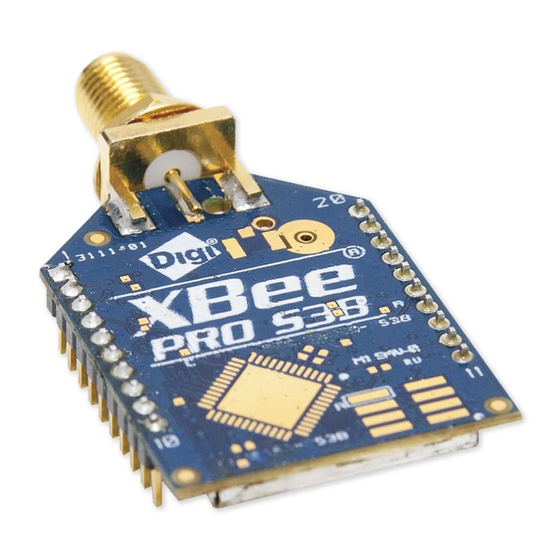
Mounting considerations for the XBee / XBee-PRO RF Module The XBee modules are designed to mount into a receptacle (socket) and therefore do not require any soldering when mounting them to a board. The XBee-PRO Development Kits contain RS-232 and USB interface boards which use two 20-pin receptacles to receive modules. -
Page 12: Pin Signals For The Xbee/Xbee-Pro Rf Module
Pin signals for the XBee/XBee-PRO RF Module Figure 3: XBee / XBee-PRO RF Module pin number (top sides shown - shields are on the bottom) Table 2: Pin assignments for the XBee-PRO Modules (Low-asserted signals are distinguished with a horizontal line above signal name.) -
Page 13: Design Notes For The Xbee/Xbee-Pro Rf Module
To help reduce noise, we recommend placing a 1.0 μF and 8.2 pF capacitor as near as possible to pin 1 on the XBee. If using a switching regulator for the power supply, switching frequencies above 500 kHz are preferred. Power supply ripple should be limited to a maximum 100 mV peak to peak. -
Page 14: Recommended Pin Connections
XBee units with the Embedded PCB Antenna should not be placed inside a metal enclosure or have any ground planes or metal objects above or below the antenna. For best results, place the XBee at the edge of the host PCB on which it is mounted. Ensure that the ground, power and signal planes are vacant immediately below the antenna section. - Page 15 Design notes for the XBee/XBee-PRO RF Module XBee / XBee-PRO RF Modules 802.15.4 Product Manual...
-
Page 16: Electrical Characteristics Of The Xbee/Xbee-Pro Rf Module
Table 5: ADC timing/performance characteristics Symbol Characteristic Condition Typical Unit k Source impedance at input Analog input voltage REFL REFH 2.08V < V < 3.6V 2.031 3.516 Ideal resolution (1 LSB) DDAD ±0.5 ±1.0 Differential non-linearity XBee / XBee-PRO RF Modules 802.15.4 Product Manual... - Page 17 This measure of error includes inherent quantization error (1/2LSB) and circuit error (differential, integral, zero-scale, and full-scale) error. The specified value of ETU assumes zero EIL (no leakage or zero real source impedance). XBee / XBee-PRO RF Modules 802.15.4 Product Manual...
-
Page 18: Xbee/Xbee-Pro Rf Module Operation
XBee/XBee-PRO RF Module operation Serial communications for the XBee/XBee-PRO RF Module The XBee / XBee-PRO RF Modules interface to a host device through a logic-level asynchronous serial port. Through its serial port, the module can communicate with any logic and voltage compatible UART;... -
Page 19: Transparent Operation
Serial communications depend on the two UARTs (the microcontroller's and the RF module's) to be configured with compatible settings (baud rate, parity, start bits, stop bits, data bits). The UART baud rate and parity settings on the XBee module can be configured with the BD and NB commands, respectively. See Command reference tables on page 40 for details. -
Page 20: Flow Control
DI Buffer. The data in the DI buffer will be transmitted over-the-air when the module is no longer receiving RF data in the network. Refer to the RO (Packetization Timeout), BD (Interface Data Rate) and D7 (DIO7 Configuration) command descriptions for more information. XBee / XBee-PRO RF Modules 802.15.4 Product Manual... -
Page 21: Adc And Digital I/O Line Support Of The Xbee/Xbee-Pro Rf Module
Refer to the D6 (DIO6 Configuration) command description for more information. ADC and Digital I/O line support of the XBee/XBee-PRO RF module The XBee / XBee-PRO RF Modules support ADC (Analog-to-digital conversion) and digital I/O line passing. The following pins support multiple functions:... -
Page 22: I/O Data Format
ADC and Digital I/O line support of the XBee/XBee-PRO RF module I/O data format I/O data begins with a header. The first byte of the header defines the number of samples forthcoming. The last two bytes of the header (Channel Indicator) define which inputs are active. -
Page 23: Dio Pin Change Detect
Applicable commands: IR (Sample Rate), IT (Samples before TX), SM (Sleep Mode) I/O line passing You can set up virtual wires between XBee / XBee-PRO Modules. When an RF data packet is received that contains I/O data, the receiving module can be setup to update any enabled outputs (PWM and DIO) based on the data it receives. -
Page 24: Configuration Example
NonBeacon (with Coordinator) networks. Peer-to-peer By default, XBee / XBee-PRO RF Modules are configured to operate within a Peer-to-peer network topology and therefore are not dependent upon Master/Slave relationships. NonBeacon systems operate within a Peer-to-peer network topology and therefore are not dependent upon Master/Slave relationships. -
Page 25: Nonbeacon (With Coordinator)
Coordinator will retain the data before discarding it. Generally, SP (Cyclic Sleep Period) and ST (Time before Sleep) parameters should be set to match the SP and ST settings of the End Devices. XBee / XBee-PRO RF Modules 802.15.4 Product Manual... - Page 26 End Devices would no longer be able to communicate with the non-beacon Coordinator. Once a Coordinator has started, the ID, CH, MY or A2 (Reassign_Channel or Reassign_PANID bits) should not be changed. XBee / XBee-PRO RF Modules 802.15.4 Product Manual...
- Page 27 Changing A1, ID or CH parameters will cause the End Device to disassociate and restart the Association procedure. If the End Device fails to associate, the AI command can give some indication of the failure. XBee / XBee-PRO RF Modules 802.15.4 Product Manual...
-
Page 28: Xbee / Xbee-Pro Addressing
Any RF module within range will accept a packet that contains a broadcast address. When configured to operate in Broadcast Mode, receiving modules do not send ACKs (acknowledgments) and transmitting modules do not automatically re-sent packets as is the case in Unicast Mode. XBee / XBee-PRO RF Modules 802.15.4 Product Manual... -
Page 29: Modes Of Operation For The Xbee/Xbee-Pro Rf Modules
When programming the module, parameters are entered in hexadecimal notation (without the “0x” prefix). Leading zeros may be omitted. Modes of operation for the XBee/XBee-PRO RF Modules XBee / XBee-PRO RF Modules operate in five modes. Figure 10: Modes of operation Idle Mode When not receiving or transmitting data, the RF module is in Idle Mode. - Page 30 Modes of operation for the XBee/XBee-PRO RF Modules The RF data packet structure follows the 802.15.4 specification. Refer to XBee / XBee-PRO addressing on page 28 for more information. Direct and indirect transmission There are two methods to transmit data: •...
-
Page 31: Sleep Mode
Modes of operation for the XBee/XBee-PRO RF Modules Note Customers in Europe who have the XBee 802.15.5 module must manage their CCA settings. See the ATCA command for CA values. Acknowledgment If the transmission is not a broadcast message, the module will expect to receive an acknowledgment from the destination node. - Page 32 Modes of operation for the XBee/XBee-PRO RF Modules The SM command is central to setting Sleep Mode configurations. By default, Sleep Modes are disabled (SM = 0) and the module remains in Idle/Receive Mode. When in this state, the module is constantly ready to respond to serial or RF activity.
-
Page 33: Command Mode
Modes of operation for the XBee/XBee-PRO RF Modules CTS will go low each time the remote wakes, allowing for communication initiated by the remote host if desired. Cyclic Sleep Remote with Pin Wake-up (SM = 5) Use this mode to wake a sleeping remote module through either the RF interface or by the de- assertion of Sleep_RQ for event-driven communications. - Page 34 Modes of operation for the XBee/XBee-PRO RF Modules Note Failure to enter AT Command Mode is most commonly due to baud rate mismatch. Ensure the ‘Baud’ setting on the “PC Settings” tab matches the interface data rate of the RF module. By default, the BD parameter = 3 (9600 b/s).
-
Page 35: Xbee/Xbee-Pro Rf Module Configuration
3. Mount the RF module to an interface board, then connect the module assembly to a PC. 4. Launch XCTU and click the 'Add devices' tab on the upper left corner of the screen. XBee / XBee-PRO RF Modules 802.15.4 Product Manual... - Page 36 Failure to enter AT Command Mode is commonly due to baud rate mismatch. Ensure that the 'Baud' setting on the 'Add radio device' window matches the interface data rate of the RF module. By default, the BD parameter = 9600 b/s. XBee / XBee-PRO RF Modules 802.15.4 Product Manual...
- Page 37 Next, scroll down on the right panel until you find the parameter you want to edit, in this case the DL (Destination Address Low) parameter, or use the search box and type "DL"; XCTU automatically scrolls to the selected parameter. XBee / XBee-PRO RF Modules 802.15.4 Product Manual...
- Page 38 Click the Write module settings button to save all of the parameters simultaneously. It is the pencil icon to the left of the Load default firmware settings button. XBee / XBee-PRO RF Modules 802.15.4 Product Manual...
-
Page 39: Remote Configuration Commands
The frame ID in the remote command request is set to 0. Command reference tables XBee / XBee-PRO RF Modules expect numerical values in hexadecimal. Hexadecimal values are designated by a “0x” prefix. Decimal equivalents are designated by a “d” suffix. Commands are contained within the following command categories (listed in the order that their tables appear): •... -
Page 40: Special
~100ms later. * Firmware version in which the command was first introduced (firmware versions are numbered in hexadecimal notation.) Networking and security Table 11: XBee / XBee-PRO commands - networking and security; sub-categories are designated within {brackets} Command Parameter Command... - Page 41 Command reference tables Table 11: XBee / XBee-PRO commands - networking and security; sub-categories are designated within {brackets} Command Parameter Command Category Name and Description Range Default Networking Destination Address Low. Set/Read the lower 32 0 - 0xFFFFFFFF {Addressing} bits of the 64-bit destination address. When combined with DH, DL defines the destination address used for transmission.
- Page 42 Command reference tables Table 11: XBee / XBee-PRO commands - networking and security; sub-categories are designated within {brackets} Command Parameter Command Category Name and Description Range Default Networking Node Identifier. Stores a string identifier. The 20-character (v1.x80*) {Identification} register only accepts printable ASCII data. A string ASCII string can not start with a space.
- Page 43 Command reference tables Table 11: XBee / XBee-PRO commands - networking and security; sub-categories are designated within {brackets} Command Parameter Command Category Name and Description Range Default Networking Destination Node. Resolves an NI (Node Identifier) 20-character (v1.x80*) {Identification} string to a physical address. The following events...
- Page 44 Command reference tables Table 11: XBee / XBee-PRO commands - networking and security; sub-categories are designated within {brackets} Command Parameter Command Category Name and Description Range Default Networking Scan Duration. Set/Read the scan duration 0-0x0F {Association} exponent. [exponent] (v1.x80*) End Device - Duration of Active Scan during Association.
- Page 45 Command reference tables Table 11: XBee / XBee-PRO commands - networking and security; sub-categories are designated within {brackets} Command Parameter Command Category Name and Description Range Default Networking End Device Association. Set/Read End Device 0 - 0x0F {Association} association options.
- Page 46 Command reference tables Table 11: XBee / XBee-PRO commands - networking and security; sub-categories are designated within {brackets} Command Parameter Command Category Name and Description Range Default Networking Association Indication. Read errors with the last 0 - 0x13 [read- (v1.x80*)
- Page 47 Command reference tables Table 11: XBee / XBee-PRO commands - networking and security; sub-categories are designated within {brackets} Command Parameter Command Category Name and Description Range Default Networking Active Scan. Send Beacon Request to Broadcast 0 - 6 (v1.x80*) {Association} Address (0xFFFF) and Broadcast PAN (0xFFFF) on every channel.
-
Page 48: Rf Interfacing
Command reference tables Table 11: XBee / XBee-PRO commands - networking and security; sub-categories are designated within {brackets} Command Parameter Command Category Name and Description Range Default Networking AES Encryption Enable. Disable/Enable 128-bit AES 0 - 1 (v1.xA0*) {Security} encryption support. Use in conjunction with the KY (disabled) command. -
Page 49: Sleep (Low Power)
Command reference tables Sleep (low power) Table 13: XBee / XBee-PRO commands - sleep (low power) Command Command Category Name and Description Parameter Range Default Sleep Sleep Mode. Set/Read Sleep Mode configurations. 0 - 5 (Low 0 = No Sleep... -
Page 50: Serial Interfacing
Command reference tables Table 13: XBee / XBee-PRO commands - sleep (low power) Command Command Category Name and Description Parameter Range Default Sleep Cyclic Sleep Period. <NonBeacon firmware> Set/ 0 - 0x68B0 [x 10 ms] (Low Read sleep period for cyclic sleeping remotes. -
Page 51: I/O Settings
Bit set to “1” specifies pull-up enabled; “0” specifies no pull-up * Firmware version in which the command was first introduced (firmware versions are numbered in hexadecimal notation.) I/O settings Table 15: XBee-PRO commands - I/O settings; sub-category designated within {brackets} Command Command Category Name and Description... - Page 52 Command reference tables Table 15: XBee-PRO commands - I/O settings; sub-category designated within {brackets} Command Command Category Name and Description Parameter Range Default I/O Settings DIO7 Configuration. Select/Read settings for 0 - 1 (v1.x80*) the DIO7 line (pin 12) of the RF module. Options 0 = Disabled include CTS flow control and I/O line settings.
- Page 53 Command reference tables Table 15: XBee-PRO commands - I/O settings; sub-category designated within {brackets} Command Command Category Name and Description Parameter Range Default I/O Settings Force Sample. Force a read of all enabled (v1.xA0*) inputs (DI or ADC). Data is returned through the UART.
-
Page 54: Diagnostics
Command reference tables Table 15: XBee-PRO commands - I/O settings; sub-category designated within {brackets} Command Command Category Name and Description Parameter Range Default I/O Settings PWM1 Output Level. Set/Read the PWM1 0 - 0x03FF (v1.xA0*) {I/O Line output level. Passing} I/O Settings PWM Output Timeout. -
Page 55: At Command Options
* Firmware version in which the command was first introduced (firmware versions are numbered in hexadecimal notation.) AT command options Table 17: XBee / XBee-PRO commands - AT command options Command Command Category Name and Description... -
Page 56: Command Descriptions For The Xbee/Xbee-Pro Rf Module
Command descriptions for the XBee/XBee-PRO RF Module Command descriptions in this section are listed alphabetically. Command categories are designated within “< >" symbols that follow each command title. XBee / XBee-PRO RF Modules expect parameter values in hexadecimal (designated by the “0x” prefix). -
Page 57: A2 (Coordinator Association) Command
1 - Coordinator will allow devices to associate to it. 3 - 7 Reserved. The binary equivalent of the default value (0x06) is 00000110. ‘Bit 0’ is the last digit of the sequence. XBee / XBee-PRO RF Modules 802.15.4 Product Manual... -
Page 58: Ac (Apply Changes) Command
Active scan found PAN, but Coordinator CH (Channel) value does not match the CH of the End Device 0x07 Energy scan timeout 0x08 Coordinator start request failed 0x09 Coordinator could not start due to invalid parameter XBee / XBee-PRO RF Modules 802.15.4 Product Manual... -
Page 59: Ap (Api Enable) Command
API instead of using the default Transparent (UART) mode. Refer to API Operation for the XBee/XBee-PRO RF Module on page 89 when API operation is enabled (AP = 1 or 2). XBee / XBee-PRO RF Modules 802.15.4 Product Manual... -
Page 60: As (Active Scan) Command
Time = [(2 ^ (SD Parameter)) * 15.36] ms. Total scan time is this time multiplied by the number of channels to be scanned (16 for the XBee, 12 for the XBee-PRO). XBee / XBee-PRO RF Modules 802.15.4 Product Manual... -
Page 61: Bd (Interface Data Rate) Command
BD parameter to vary from the parameter that was sent (refer to the table below). Reading the BD command (send “ATBD” command without an associated parameter value) will return the value actually stored in the module’s BD register. XBee / XBee-PRO RF Modules 802.15.4 Product Manual... -
Page 62: Ca (Cca Threshold) Command
RF module into AT Command Mode so that data entering the module from the host is recognized as commands instead of payload. The AT Command Sequence is explained further in the AT Command Mode on page 33. XBee / XBee-PRO RF Modules 802.15.4 Product Manual... -
Page 63: Ce (Coordinator Enable) Command
Adjacent channel rejection is 23 dB. The module uses channel numbers of the 802.15.4 standard. Center Frequency = 2.405 + (CH - 11d) * 5 MHz(d = decimal) Refer to the XBee/XBee-PRO Addressing section for more information. CN (Exit Command Mode) command AT Command: ATCN <AT Command Mode Options>... -
Page 64: Ct (Command Mode Timeout) Command
<I/O Settings> The D0, D1, D2, D3 and D4 commands are used to select/read the behavior of their respective AD/DIO lines (pins 20, 19, 18, 17 and 11 respectively). Options include: • Analog-to-digital converter • Digital input • Digital output XBee / XBee-PRO RF Modules 802.15.4 Product Manual... -
Page 65: D5 (Dio5 Configuration) Command
D6 (DIO6 Configuration) command AT Command: ATD6 Parameter Range:0 - 5 Parameter Configuration Disabled RTS Flow Control DO low DO high Default Parameter Value:0 Parameters 3-5 supported as of firmware version 1.xA0 XBee / XBee-PRO RF Modules 802.15.4 Product Manual... -
Page 66: D7 (Dio7 Configuration) Command
RS485 TX Enable (this output is 3V CMOS level, and is useful in a 3V CMOS to RS485 conversion circuit) D8 (DI8 Configuration) command AT Command: ATD8 Parameter Range:0 - 5 (1, 2, 4 and 5 n/a) Parameter Configuration XBee / XBee-PRO RF Modules 802.15.4 Product Manual... -
Page 67: Da (Force Disassociation) Command
An module will only communicate with other modules having the same channel (CH parameter), PAN ID (ID parameter) and destination address (DH + DL parameters). XBee / XBee-PRO RF Modules 802.15.4 Product Manual... -
Page 68: Dl (Destination Address Low) Command
To transmit using a 16-bit address, set the DH parameter to zero and the DL parameter less than 0xFFFF. 0x000000000000FFFF (DL concatenated to DH) is the broadcast address for the PAN. Refer to the XBee/XBee-PRO Addressing section for more information. DL (Destination Address Low) command... -
Page 69: Ea (Ack Failures) Command
Set the EC parameter to “0” to reset count. ED (Energy Scan) command AT Command: ATED Parameter Range:0 - 6 Related Command: SD (Scan Duration), SC (Scan Channel) Minimum Firmware Version Required: v1.x80 XBee / XBee-PRO RF Modules 802.15.4 Product Manual... -
Page 70: Ee (Aes Encryption Enable) Command
<Networking {Security}> The EE command is used to set/read the parameter that disables/enables 128-bit AES encryption. The XBee / XBee-PRO firmware uses the 802.15.4 Default Security protocol and uses AES encryption with a 128-bit key. AES encryption dictates that all modules in the network use the same key and the maximum RF packet size is 95 bytes. -
Page 71: Fr (Software Reset) Command
<I/O Settings {I/O Line Passing}> The IA command is used to bind a module output to a specific address. Outputs will only change if received from this address. The IA command can be used to set/ read both 16 and 64-bit addresses. XBee / XBee-PRO RF Modules 802.15.4 Product Manual... -
Page 72: Id (Pan Id) Command
(where each bit represents the level of an I/O line that is setup as an output.) Minimum Firmware Version Required: v1.xA0 <I/O Settings> The IO command is used to set digital output levels. This allows DIO lines setup as outputs to be changed through Command Mode. XBee / XBee-PRO RF Modules 802.15.4 Product Manual... -
Page 73: Ir (Sample Rate) Command
88 bytes of sample data. Since the module uses a 10-bit A/D converter, each sample uses two bytes. This leads to a maximum buffer size of 44 samples or IT=0x2C. XBee / XBee-PRO RF Modules 802.15.4 Product Manual... -
Page 74: Iu (I/O Output Enable) Command
When queried, the system will return an ‘OK’ message and the value of the key will not be returned. M0 (PWM0 Output Level) command AT Command: ATM0 Parameter Range:0 - 0x03FF [steps] Default Parameter Value:0 XBee / XBee-PRO RF Modules 802.15.4 Product Manual... -
Page 75: M1 (Pwm1 Output Level) Command
Digi Mode (802.15.4 + Digi header) 802.15.4 (no ACKs) 802.15.4 (with ACKs) Digi Mode (no ACKs) Default Parameter Value:0 Related Commands: ND (Node Discover), DN (Destination Node) Minimum Firmware Version Required: v1.x80 XBee / XBee-PRO RF Modules 802.15.4 Product Manual... -
Page 76: My (16-Bit Source Address) Command
Digi header contained in the 802.15.4 RF packet. By default (MM = 0), Digi Mode is enabled and the module adds an extra header to the data portion of the 802.15.4 packet. This enables the following features: •... -
Page 77: Nd (Node Discover) Command
4 bytes for SH (Serial Number High) value 4 bytes for SL (Serial Number Low) value 1 byte for DB (Received Signal Strength) value NULL-terminated string for NI (Node Identifier) value (max 20 bytes w/out NULL terminator) XBee / XBee-PRO RF Modules 802.15.4 Product Manual... -
Page 78: Ni (Node Identifier) Command
<Networking {Identification}> The NT command is used to set the amount of time a base node will wait for responses from other nodes when using the ND (Node Discover) command. The NT value is transmitted with the ND command. XBee / XBee-PRO RF Modules 802.15.4 Product Manual... -
Page 79: P0 (Pwm0 Configuration) Command
Width Modulation output 1). This command enables the option of translating incoming data to a PWM so that the output can be translated back into analog form. With the IA (I/O Input Address) parameter correctly set, AD1 values can automatically be passed to PWM1. XBee / XBee-PRO RF Modules 802.15.4 Product Manual... -
Page 80: Pl (Power Level) Command
<RF Interfacing> The PL command is used to select and read the power level at which the RF module transmits conducted power. When operating in Europe, XBee-PRO 802.15.4 modules must operate at or below a transmit power output level of 10dBm. Customers have 2 choices for transmitting at or below 10dBm: •... -
Page 81: Pt (Pwm Output Timeout) Command
After a time, the process ends and the data is lost. RO (Packetization Timeout) command AT command: ATRO Parameter range:0 - 0xFF [x character times] Default parameter value: 3 XBee / XBee-PRO RF Modules 802.15.4 Product Manual... -
Page 82: Rp (Rssi Pwm Timer) Command
PWM output and it will always reflect the value of the last received RF packet. RR (XBee Retries) command AT command: ATRR Parameter range: 0 - 6 Default: 0 Minimum firmware version required: 1.xA0 XBee / XBee-PRO RF Modules 802.15.4 Product Manual... -
Page 83: Sc (Scan Channels) Command
ACK (acknowledgment). If the transmitting module does not receive an ACK within 200 msec, it will re-send the packet within a random period up to 48 msec. Each XBee retry can potentially result in the MAC sending the packet four times (one try plus three retries). Note that retries are not attempted for packets that are purged when transmitting with a Cyclic Sleep Coordinator. -
Page 84: Sd (Scan Duration) Command
Scan Time is measured as ((# of Channels to Scan) * (2 ^ SD) * 15.36ms). The number of channels to scan is set by the SC command. The XBee RF Module can scan up to 16 channels (SC = 0xFFFF). The XBee PRO RF Module can scan up to 12 channels (SC = 0x1FFE). -
Page 85: Sm (Sleep Mode) Command
0 - Normal operations. A module configured for cyclic sleep will poll for data on waking. • 1 - Disable wakeup poll. A module configured for cyclic sleep will not poll for data on waking. Bit 1 - ADC/DIO wakeup sampling disable. XBee / XBee-PRO RF Modules 802.15.4 Product Manual... -
Page 86: Sp (Cyclic Sleep Period) Command
Set/Read time period of inactivity (no serial or RF data is sent or received) before activating Sleep Mode. ST parameter is only valid with Cyclic Sleep settings (SM = 4 - 5). Coordinator and End Device ST values must be equal. XBee / XBee-PRO RF Modules 802.15.4 Product Manual... -
Page 87: T0 - T7 ((D0-D7) Output Timeout) Command
<Diagnostics> The VR command is used to read which firmware version is stored in the module. XBee version numbers will have four significant digits. The reported number will show three or four numbers and is stated in hexadecimal notation. A version can be reported as “ABC” or “ABCD”. Digits ABC are the main release number and D is the revision number from the main release. -
Page 88: Api Operation For The Xbee/Xbee-Pro Rf Module
API Operation for the XBee/XBee-PRO RF Module By default, XBee / XBee-PRO RF Modules act as a serial line replacement (Transparent Operation) - all UART data received through the DI pin is queued up for RF transmission. When the module receives an RF packet, the data is sent out the DO pin with no additional information. - Page 89 To calculate: Not including frame delimiters and length, add all bytes keeping only the lowest 8 bits of the result and subtract from 0xFF. To verify: Add all bytes (include checksum, but not the delimiter and length). If the checksum is correct, the sum will equal 0xFF. XBee / XBee-PRO RF Modules 802.15.4 Product Manual...
-
Page 90: Api Types
The “AT Command” API type allows for module parameters to be queried or set. When using this command ID, new parameter values are applied immediately. This includes any register set with the “AT Command - Queue Parameter Value” (0x09) API type. XBee / XBee-PRO RF Modules 802.15.4 Product Manual... - Page 91 Some commands will send back multiple frames (for example, the ND (Node Discover) and AS (Active Scan) commands). These commands will end by sending a frame with a status of ATCMD_OK and no cmdData. XBee / XBee-PRO RF Modules 802.15.4 Product Manual...
- Page 92 If no characters present, 0xFFFE. All other bits must be set to 0. the register is queried. XBee / XBee-PRO RF Modules 802.15.4 Product Manual...
- Page 93 All other bits must be set to 0. TX (Transmit) Request: 16-bit address API identifier value: 0x01 A TX Request message will cause the module to transmit data as an RF Packet. XBee / XBee-PRO RF Modules 802.15.4 Product Manual...
- Page 94 Timeout is defined as (2.5 x SP (Cyclic Sleep Period) parameter value). RX (Receive) packet: 64-bit address API identifier value: 0x80 When the module receives an RF packet, it is sent out the UART using this message type. XBee / XBee-PRO RF Modules 802.15.4 Product Manual...
- Page 95 “0x28” (40 decimal) is returned) bits 3-7 [reserved] RX (Receive) Packet: 64-bit address IO API identifier value: 0x82 I/O data is sent out the UART using an API frame. Figure 27: RX packet (64-bit address) frames XBee / XBee-PRO RF Modules 802.15.4 Product Manual...
- Page 96 API Operation for the XBee/XBee-PRO RF Module RX (Receive) packet: 16-bit address IO API identifier value: 0x83 I/O data is sent out the UART using an API frame. Figure 28: RX packet (16-bit address) frames XBee / XBee-PRO RF Modules 802.15.4 Product Manual...
-
Page 97: Agency Certifications
Agency certifications United States (FCC) XBee / XBee-PRO RF Modules comply with Part 15 of the FCC rules and regulations. Compliance with the labeling requirements, FCC notices and antenna usage guidelines is required. To fulfill FCC Certification requirements, the OEM must comply with the following regulations: 1. -
Page 98: Fcc-Approved Antennas (2.4 Ghz)
The modules are FCC-approved for fixed base station and mobile applications on channels 0x0B - 0x1A (XBee) and 0x0C - 0x17 (XBee-PRO). If the antenna is mounted at least 20cm (8 in.) from nearby persons, the application is considered a mobile application. Antennas not listed in the table must be tested to comply with FCC Section 15.203 (Unique Antenna Connectors) and Section 15.247... - Page 99 FCC-approved antennas (2.4 GHz) Table 21: Antennas approved for use with the XBee RF Modules (Cable loss is required) Part Number Type (Description) Gain Application* Min. Separation Required Cable-loss Yagi Class Antennas A24-Y4NF Yagi (4-element) 6.0 dBi Fixed A24-Y6NF Yagi (6-element) 8.8 dBi...
- Page 100 Flat Panel 15.0 dBi Fixed 8 dB A24-P16NF Flat Panel 16.0 dBi Fixed 9 dB Table 22: Antennas approved for use with the XBee / XBee-PRO RF Modules (Cable-loss is required) Min. Required Cable- Part Number Type (Description) Gain Application* Separation...
- Page 101 FCC-approved antennas (2.4 GHz) Table 22: Antennas approved for use with the XBee / XBee-PRO RF Modules (Cable-loss is required) Min. Required Cable- Part Number Type (Description) Gain Application* Separation loss A24-F5NF Omni-directional (Fiberglass base 5.0 dBi Fixed/ 20 cm 7.1 dB...
-
Page 102: Rf Exposure
FCC RF Exposure compliance. Europe (ETSI) The XBee RF Modules have been certified for use in several European countries. For a complete list, refer to www.digi.com If the XBee RF Modules are incorporated into a product, the manufacturer must ensure compliance of the final product to the European harmonized EMC and low-voltage/safety standards. -
Page 103: Approved Antennas
Files can be obtained by contacting Digi Support. Important Note: Digi does not list the entire set of standards that must be met for each country. Digi customers assume full responsibility for learning and meeting the required guidelines for each country in their distribution market. -
Page 104: Canada (Ic)
For XBee radios, a clearly visible label on the outside of the final product enclosure must display the following text: ID: R201WW07215214 For XBee-PRO radios, the RF power must be 10 dBm (10 mW) and a clearly visible label on the outside of the final product enclosure must display the following text: ID: R201WW08215111 ANATEL (Brazil) certification The XBee RF modules with 802.15.4 firmware (models noted in conformity information below) - Page 105 ANATEL (Brazil) certification The XBee-PRO RF modules with 802.15.4 firmware (models noted in conformity information below) comply with Brazil ANATEL standards in Resolution No. 506. The following information is required in the user manual for the product containing the radio and on the product containing the radio (in Portuguese): XBee / XBee-PRO RF Modules 802.15.4 Product Manual...
Need help?
Do you have a question about the XBee and is the answer not in the manual?
Questions and answers