Advertisement
Quick Links
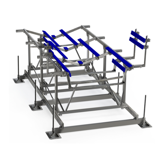
Over-Center
24,000 lbs Capacity
ASSEMBLY
INSTALLATION
REPLACEMENT PARTS
866-GO-BASTA
www.gobasta.com
Basta Inc. Bellevue WA 98005 USA
tm
Hydraulic Steel Lift
Model # 24k
READ complete manual CAREFULLY
BEFORE attempting assembly or operation
60
©
Copyright 2019 Basta Inc
24k
60
11/21
L392-0091, REV C
Advertisement

Subscribe to Our Youtube Channel
Related Manuals for Basta Boatlifts Over-Center 24k60

Summary of Contents for Basta Boatlifts Over-Center 24k60
- Page 1 Over-Center Hydraulic Steel Lift 24,000 lbs Capacity Model # 24k ASSEMBLY READ complete manual CAREFULLY INSTALLATION BEFORE attempting assembly or operation REPLACEMENT PARTS 866-GO-BASTA www.gobasta.com 11/21 Basta Inc. Bellevue WA 98005 USA © L392-0091, REV C Copyright 2019 Basta Inc...
- Page 2 INDEX Warning ..……………………................Page 2 Parts Assembly Diagram ................Page 3 Assembly Instructions .................Pages 4 - 12 First Use / Adjustments ..……………............Page 13 Basta Marine Boat Lift Accessories ..…………………..…………..…...Page 16 Troubleshooting / FAQ .…................Page 14 Warranty ......…................Page 15 WARNING NOTE: Your boat lift is a very heavy piece of equipment. Improper use could result in serious injury or death.
- Page 3 INSPECT Before Using: the lift monthly for frayed hoses, loose Read this manual fasteners and corrosion completely! lift unattended OIL INJECTED INTO THE SKIN FROM HIGH PRESSURE LEAKS IN HYDRAULIC SYSTEMS CAN CAUSE SEVERE INJURY. MOST DAMAGE OCCURS DURING THE FIRST FEW HOURS.
- Page 4 MODEL 24k ITEM PART # DESCRIPTION W110-0026 Base Crossmember W104-0024 Left Side Rail W104-0025 Right Side Rail W101-0049 H-Frame, Aft W101-0048 H-Frame, Center W101-0047 H-Frame, Forward W113-0022 Bunk Rail K200-0012 Adjustable Support Leg F730-0013 Leg Cap W113-0029 Bunk Chevron, Forward W113-0031 Bunk Chevron, Mid W113-0030...
- Page 5 NOTE: VIEW FROM OTHER SIDE HARDWARE ITEM PART # DESCRIPTION PRE-INSTALLED (ALL BUNKS) S103-0807 5/8” x 1-1/2” hex head set screw, SS S103-0707 1/2” x 1-1/2” hex head cap screw, SS S313-0010 1/2” flat washer, SS S362-0010 1/2” nylon insert lock nut, SS S103-1020 1”...
- Page 6 ASSEMBLY INSTRUCTIONS tighten leg set screws alternately to push the leg securely into the corner of the leg socket step HARDWARE apply a small amount of grease to bolt threads page 6 ? parts identified on page 4...
- Page 7 B1 B2 B1 B2 B1 B2 B2 B3 step HARDWARE apply a small amount of grease to bolt threads ? parts identified on page 4 do not tighten these bolts do not tighten these bolts completely until the H-frames completely until the H-frames and bunks have been and bunks have been installed &...
- Page 8 ASSEMBLY INSTRUCTIONS FORWARD CENTER step HARDWARE apply a small C2 C3 amount of grease to bolt threads page 8 ? parts identified on page 4...
- Page 9 FORWARD CENTER step HARDWARE apply a small amount of grease to bolt threads ? parts identified on page 4 C2 C3 FORWARD CENTER step HARDWARE apply a small C2 C3 amount of grease to bolt threads page 9 ? parts identified on page 4...
- Page 10 ASSEMBLY INSTRUCTIONS tighten these nuts only “finger tight” until the cylinders are installed D2 D3 step HARDWARE apply a small amount of grease to bolt threads page 10 ? parts identified on page 4...
- Page 11 NOTE: Install cylinder with lift in 'down' position E2 E1 step HARDWARE ? parts identified NOTICE on page 4 install the clevis pins tighten the bunk rail nuts and “E2” with their heads crossmember bolts after toward the inside of the lift all the cylinders are installed step HARDWARE...
- Page 12 leave bolts loose until bunk boards are installed approximate starting locations 198cm 198cm 94cm 104cm 37” 78” 78” 41” F2 F3 F2 F3 step HARDWARE apply a small amount of grease to bolt threads page 12 ? parts identified on page 4...
- Page 13 F1 F2 F2 F3 step HARDWARE apply a small amount of grease to bolt threads ? parts identified on page 4 leave bolts loose leave bolts loose until bunk boards until bunk boards are installed are installed F2 F3 step HARDWARE apply a small amount of grease...
- Page 14 step HARDWARE apply a small amount of grease to bolt threads page 14 ? parts identified on page 4...
- Page 15 step HARDWARE apply a small amount of grease to bolt threads ? parts identified NOTICE on page 4 the bunks may have to be adjusted remember to tighten all the several times for the best fit - bolts installed in Step 10 WITHOUT BOAT ON LIFT! step HARDWARE...
- Page 16 step HARDWARE apply a small amount of grease to bolt threads ? parts identified on page 4 page 27...
- Page 17 NOTE: pump appearance may vary Battery Battery Battery Battery Battery Battery Group 31 Group 31 marine marine deep cycle deep cycle 1. The Hydraulic Pump will arrive fully assembled. Make s u re all the connections are snug to prevent leaks or loss of power to the unit.
- Page 18 POWER SYSTEM COMPONENTS SOLAR PANEL ASSEMBLY R281-0004 NOTE: pump appearance may vary Padlock not included ENCLOSURE C243-0006 NOTE: NOTE: REMOVE SHIPPING PLUG IN REMOVE SHIPPING PLUG IN RESERVOIR AND REPLACE RESERVOIR AND REPLACE WITH BREATHER PLUG WITH BREATHER PLUG BEFORE START-UP BEFORE START-UP CONTROL PANEL ASSEMBLY...
- Page 19 step HARDWARE apply a small amount of grease to bolt threads ? parts identified on page 4 step HARDWARE apply a small amount of grease to bolt threads page 19 ? parts identified on page 4...
- Page 20 step HARDWARE apply a small amount of grease to bolt threads ? parts identified on page 4 remember to tighten note how bunk chevron all the bolts installed fits between forward and in Step 10 aft bunk board stanchions Buffer Tube NOTE: FWD BUNK CHEVRONS MAY BE USED AS CD MOUNTS...
- Page 21 FIRST USE AND ADJUSTMENTS First test lift on dry ground for oil leaks, remote control function and correct operation. IMPORTANT: After installation, the legs MUST be adjusted so that the lift frame is level. Lift must move into Over-Center position when fully raised. 232.5”...
- Page 22 MAINTENANCE Occasionally wipe the solar panel with a clean, damp cloth to preserve its charging performance. WARNING After the lift is assembled and installed, all fasteners should be checked for proper tightness and reinspected periodically. NOTICE INSPECT THE LIFT PERIODICALLY Once a month: Inspect the hoses, cylinders and fittings for leaks and wear.
- Page 23 Q: IS THE HYDRAULIC FLUID SAFE FOR THE FISH? We use a special low-toxicity hydraulic fluid that is safe for the environment. This fluid is different than food-grade oil. Only use Basta Boatlifts approved fluid in your hydraulic system. Q: WHAT IF I GET A NEW BOAT? Re-leveling the boat lift may be necessary.
- Page 24 1.This lift uses two 12V Group 31 marine deep-cycle batteries. When looking A fully automatic battery charger or for a replacement, note that the figure for Reserve Capacity is the most trickle charger may be used. important feature. Heavier batteries usually have more reserve capacity. Do NOT use a high power manual or boost charger 2.The batteries should not be allowed to remain in a substantially discharged unless the battery is disconnected!
- Page 25 Your boat lift is a piece of heavy power equipment that lifts a load that weighs thousands of pounds. Failure to comply with the following rules may result in severe injury, death or property damage. 1. Be alert and aware at all times. Do not operate while under the influence of drugs or alcohol. 2.
- Page 26 Products. on the water. Welcome to the Basta Boatlifts family and Boat Happy! Labor for warranty work to be provided by the Company’s Authorized dealer for a period of 3 years from Warranty Start Date, provided there is an active Authorized Basta Inc.
- Page 27 ACCESSORIES FOR MOST BASTA BOATLIFTS For additional information and images visit our web site at www.gobasta.com or contact Basta Marine at 1-866-GOBASTA for a catalog. Centering Devices Power Unit Support Bracket These vertical reference guides Safely secure the power unit box...
- Page 28 Basta, Inc. Bellevue WA 98005 USA...
Need help?
Do you have a question about the Over-Center 24k60 and is the answer not in the manual?
Questions and answers