Table of Contents
Advertisement
Quick Links
REVISION 0
FAX-L1000
FAX-L1000
FAX-L1000
FAX-L1000
FAX-L1000
FAX-L1000
OPTION MEMORY VII (4MB)
VERIFICATION STAMP UNIT1
YELLOW INK TO REFILL
PAPER FEED UNIT PF-52
ENVELOPE FEEDER EF-52
DUPLEX UNIT DU-52
FAX-L1000 ISDN KIT
FAX-L1000 Printer Kit
RAM DIMM MODULE
FAX-L1000 PostScript Kit
FAX-L1000 Network
FEB. 2000
COPYRIGHT © 2000 CANON INC.
FOR VERIFICATION STAMP
Printer Upgrade kit
HY8-10AN-000
CANON FAX-L1000 FEB. 2000 PRINTED IN JAPAN (IMPRIME AU JAPON)
H12-1613 230V EC
H12-1614 230V UK
H12-1615 230V GER
H12-1617 230V FRN
H12-1618 230V AUS
H12-1619 230V AE
H11-4721
H12-3162
H12-3372
R73-5006
R73-5005
R73-5004
H11-5553
H11-5513
H11-5533
H11-5543
Advertisement
Chapters
Table of Contents

Related Manuals for Canon FAX L1000


Summary of Contents for Canon FAX L1000
- Page 1 COPYRIGHT © 2000 CANON INC. H12-1613 230V EC H12-1614 230V UK H12-1615 230V GER H12-1617 230V FRN H12-1618 230V AUS H12-1619 230V AE H11-4721 H12-3162 H12-3372 R73-5006 R73-5005 R73-5004 H11-5553 H11-5513 H11-5533 H11-5543 HY8-10AN-000 CANON FAX-L1000 FEB. 2000 PRINTED IN JAPAN (IMPRIME AU JAPON)
- Page 2 This manual is copyrighted with all rights reserved. Under the copyright laws, this manual may not be copied, reproduced or translated into another language, in whole or in part, without the written consent of Canon Inc.. Copyright © 2000 by Canon Inc.
- Page 3 I. MEANINGS OF MARKS The marks used in this manual have the following meanings. Mark Meaning Indicates a general caution or warning, or otherwise to communicate the presence of a hazard. Warns of the possibility of an electric shock. Informs you of fire-related cautions. Warns against disassembly of parts.
- Page 4 II. ABOUT THIS MANUAL This manual consists of the following five chapters, each providing appropriate information needed to service the product. Chapter 1: Safety and Precautions Provides cautions and warnings needed when servicing the product while ensuring safety, and explains the protective functions built into the product. Be sure to go through the descriptions.
-
Page 5: Revision History
III. REVISION HISTORY REVISION CONTENT Original... -
Page 6: Table Of Contents
IV. TABLE OF CONTENTS Chapter 1: Safety and Precautions Page 1 - 1 1. DANGER TO PERSONNEL 1 - 1 1.1 Electric Shock 1 - 2 1.1.1 AC line (AC 230V household current) 1 - 2 1.1.2 Telephone line 1 - 2 1.1.3 Printer high voltage terminal 1 - 3 1.2 High Temperature Parts... - Page 7 Chapter 2: Operating Instructions 2 - 1 1. NAMES OF PARTS AND THEIR FUNCTIONS 2 - 1 1.1 Main Unit Overview 2 - 4 1.2 Operation Panel 2 - 7 2. BASIC OPERATION 2 - 7 2.1 Copying 2 - 8 2.2 Telephone (Only possible where a handset or telephone are connected) 2 - 9...
- Page 8 3 - 18 2.1.2 Option overview 3 - 19 2.1.3 Consumables 3 - 21 2.2 Mechanical Overview 3 - 21 2.2.1 Unit layout diagrams 3 - 21 2.2.2 Document and recording paper flow 3 - 23 2.2.3 Drive system layout 3 - 25 2.2.4 Electrical system layout 3 - 30...
- Page 9 4 - 7 2. CONSUMABLES REPLACEMENT 4 - 7 2.1 Toner Cartridge 4 - 7 2.2 Recording Paper 4 - 8 2.3 Stamp Ink 4 - 11 3. CLEANING 4 - 11 3.1 Main Unit 4 - 11 3.2 Document Pick-up Roller 4 - 11 3.3 Separation Roller (Upper) 4 - 11...
-
Page 10: Envelope Feeder Ef
5 - 43 2. SERVICE TOOLS 5 - 43 2.1 Printer Driver Tester 5 - 43 2.1.1 Outline 5 - 44 2.1.2 Explanation of LEDs and Switches 5 - 45 2.1.3. Operation 5 - 51 3. OPTION 5 - 51 3.1 Option Memory VII (4M-BYTE) 5 - 51 3.1.1 Safety and precautions... - Page 11 5 - 209 3.8.2 Service operations 5 - 214 3.8.3 Technical Information 5 - 214 3.8.4 Maintenance and service 5 - 215 3.9 RAM DIMM Module 5 - 215 3.9.1 Safety and precautions 5 - 215 3.9.2 Service operations 5 - 217 3.9.3 Technical informations 5 - 218 3.9.4 Maintenance and service...
-
Page 12: Illustration Index
V. ILLUSTRATION INDEX Chapter 1: Safety and Precautions Page 1 - 2 Figure 1 - 3 Figure 1 - 7 Figure 1 - 8 Figure 1 - 9 Figure 1 - 10 Figure 1 - 11 Figure 1 - 13 Figure 1 - 14 Figure... -
Page 13: Chapter 3: Technical Reference
2 - 35 Figure 2 - 29 User Menu Settings (10/13) 2 - 36 Figure 2 - 30 User Menu Settings (11/13) 2 - 37 Figure 2 - 31 User Menu Settings (12/13) 2 - 38 Figure 2 - 32 User Menu Settings (13/13) 2 - 40 Figure 2 - 33 Slide Switch Location on NCU Board... - Page 14 3 - 54 Figure 3 - 24 Drum Cleaning 3 - 55 Figure 3 - 25 High Voltage Terminals 3 - 56 Figure 3 - 26 Transfer 3 - 56 Figure 3 - 27 Separation 3 - 57 Figure 3 - 28 Fixing section 3 - 60 Figure 3 - 29 Function Block Diagram (1)
- Page 15 4 - 19 Figure 4 - 16 Cleaning Location 2 4 - 20 Figure 4 - 17 Preparation for Cleaning 1 4 - 20 Figure 4 - 18 Preparation for Cleaning 2 4 - 21 Figure 4 - 19 Cleaning Location 1 4 - 21 Figure 4 - 20 Cleaning Location 2...
- Page 16 5 - 61 Figure 5 - 14 External View 5 - 61 Figure 5 - 15 Attachment to the Main Unit 1 5 - 62 Figure 5 - 16 Attachment to the Main Unit 2 5 - 62 Figure 5 - 17 Attachment to the Main Unit 3 5 - 63 Figure 5 - 18 Attachment to the Main Unit 4...
- Page 17 5 - 144 Figure 5 - 64 System Data List (7/10) 5 - 145 Figure 5 - 65 System Data List (8/10) 5 - 146 Figure 5 - 66 System Data List (9/10) 5 - 147 Figure 5 - 67 System Data List (10/10) 5 - 148 Figure 5 - 68 System Dump List (1/3)
- Page 18 This page intentionally left blank...
- Page 19 Chapter 1 Safety and Precautions...
-
Page 21: Danger To Personnel
FAX-L1000 Chapter 1: Safety and Precautions 1. DANGER TO PERSONNEL 1.1 Electric Shock Precautions Before disassembling the fax, carry out the following to prevent electric shock: (1) Disconnect the power cord from the outlet. (2) Disconnect the modular jack cord (telephone line) from the fax. Precautions when servicing the fax with the power on When you must service the fax with the power cord plugged in, you must not ground your body with grounding wrist straps. -
Page 22: Ac Line (Ac 230V Household Current)
FAX-L1000 Chapter 1: Safety and Precautions 1.1.1 AC line (AC 230V household current) Power supply unit (primary side) The AC 230V is supplied to the primary side of the power supply unit when the power cord is plugged in. 1.1.2 Telephone line NCU board (primary side) When connected to the telephone line, a line voltage of approx. -
Page 23: High Temperature Parts
1.2 High Temperature Parts Precautions To prevent burns while disassembling the fax, disconnect the power cord at least 10 minutes before starting disassembly, to allow high temperature parts to cool down. How to treat burns Heat of about 122°F (50°C) or more causes burns. Also, the longer the contact, the more severe the burn. -
Page 24: Fire
FAX-L1000 Chapter 1: Safety and Precautions 1.3 Fire Danger Do not throw the lithium battery or the toner cartridge into fire. Lithium battery The lithium battery contain lithium, organic solvents and other combustible substances. If the lithium battery is thrown into fires, it may rupture and burn fiercely. - Page 25 FAX-L1000 Chapter 1: Safety and Precautions This page intentionally left blank...
-
Page 26: Moving And Rotating Parts
FAX-L1000 Chapter 1: Safety and Precautions 1.4 Moving and Rotating Parts Precautions To prevent accidents involving moving or rotating parts during servicing, that disconnect the power cord before starting disassembly. When you must service the fax with the power cord plugged in, you must not wear bracelets, necklaces, neckties, or other objects. - Page 27 Read motor Document feed roller Document eject roller DC motor Read motor Document feed roller Paper feed roller Fixing eject roller Pressure roller Figure 1-3 Moving and Rotating Parts FAX-L1000 Chapter 1: Safety and Precautions Separation roller (Upper) Main motor Pressure roller Separation roller (Upper) Separation roller (Lower)
-
Page 28: Laser Beams
FAX-L1000 Chapter 1: Safety and Precautions 1.5 Laser Beams This fax is a Class 1 Laser Product as defined in the EN60825 (IEC825) Radiation Safety of laser products, equipment classification, requirements and user’s guide. This means that this product uses lasers that do not radiate dangerous laser beam and conforms to the regulations because the laser beam does not affect the user during operations. - Page 29 FAX-L1000 Chapter 1: Safety and Precautions Laser/Scanner unit Laser light Laser shutter FX6 toner cartridge Figure 1-5 Laser Shutter...
-
Page 30: Danger To Equipment
FAX-L1000 Chapter 1: Safety and Precautions 2. DANGER TO EQUIPMENT 2.1 Handling the FAX General Precautions TO AVOID SERIOUS INJURY, NEVER DISASSEMBLE THE FAX. EXPOSED POWER POINTS INSIDE THE FAX CAN CAUSE ELECTRICAL SHOCK IF YOU TOUCH THEM. After you unplug the fax unit, always wait at least 5 seconds before you plug it in again. - Page 31 FAX-L1000 Chapter 1: Safety and Precautions Before you transport the fax, remove the cartridge. To protect the cartridge from bright light, cover it with its original protective bag or a cloth. Keep liquids, cleaners, and other solvents away from the fax unit.
-
Page 32: Storage And Handling Of Fx6 Toner Cartridge
FAX-L1000 Chapter 1: Safety and Precautions 2.2 Storage and Handling of FX6 Toner Cartridge Whether the cartridge is still sealed in its box or installed in the printer, the effect of the natural environment will change it over time regardless of the number of prints. As the progression of this natural change depends on the storage or installation environment, take sufficient care in storing and handling the cartridges. -
Page 33: Storing Unsealed Parts
2.2.2 Storing unsealed parts As an organic photoconductor (OPC) is used in the photosensitive drum, it will deteriorate if exposed to strong light. As there is also toner in the cartridge, be sure to explain to the customer the need to be careful in handling and storing unsealed cartridges. 2.2.3 Storage environment a) Be sure to store in the protective bag. - Page 34 FAX-L1000 Chapter 1: Safety and Precautions After loading the cartridge in the printer, print 3 to 5 sheets of test patterns and check for toner leakage to prevent output image from dirt. (2) Remove the cartridge from the printer before transporting it. During transportation, the cartridge must be kept in the protective bag or thick cloth to prevent direct exposure to light.
-
Page 35: Precautions When Servicing
2.3 Precautions when Servicing 2.3.1 Damage due to electrostatic discharge This fax contains contact sensor and printed circuit boards that use many electrical components such as ROM, RAM and custom ICs. A static charge can damage these components, so, care must be taken to prevent damage caused by electrostatic discharge when disassembling the fax. -
Page 36: Lubrication Points
FAX-L1000 Chapter 1: Safety and Precautions 2.3.2 Lubrication points Do not touch the greased parts. If you do, the grease (applied for smooth operation of the printer mechanism and to increase electrical conductivity) will come off. Use only specified grease. If you use other grease, the grease may oxidize, and weaken plastic parts. -
Page 37: Printer Section
2.3.4 Printer section a) Transfer charging roller If skin, oil or, the like, gets on the rubber section of the transfer charging roller, the rear side of the recording paper can be soiled, and blank patches can occur in printing. During disassembly, hold the shaft at both ends of the transfer charging roller. -
Page 38: Paper Load Section
FAX-L1000 Chapter 1: Safety and Precautions 2.3.5 Paper load section a) Pickup Roller Position When having assembled the paper pickup roller after parts replacement, before setting the cassette 1 or the cassette 2, install the toner cartridge, close the printer cover, connect the power cord, and the cassette pickup roller moves automatically to its initial position. -
Page 39: Control Boards
2.3.6 Control boards a) SCNT board Jumper plug JP3 and J6 are for factory check only. Service technician must not remove it. SCNT board data User data, service data are stored in memory on the SCNT board. Therefore, these data must be printed out before replacing the SCNT board. REFERENCE For details, see this Chapter, 3. -
Page 40: Replacing Rom
FAX-L1000 Chapter 1: Safety and Precautions 2.3.7 Replacing ROM Observe the following precautions when replacing the ROM on the SCNT board, for example, when replacing a defective ROM or when upgrading the software. a) Preparation Print out all battery backed up data. Reception image data in image memory is erased approx. -
Page 41: Precautions For Data Protection
3. PRECAUTIONS FOR DATA PROTECTION 3.1 Battery-backed up Data The SCNT board is provided with a function for backing up data in control processing memory (SRAM) and image storage memory (DRAM) by lithium battery, and rechargeable battery, even if a power interruption occurs, or the power cord is disconnected by accident. The back up time for image data with the secondary vanadium-lithium battery is approximately 12 hours. -
Page 42: Backed Up By Rechargeable Battery
FAX-L1000 Chapter 1: Safety and Precautions 3.2 Backed up by Rechargeable Battery The data stored in the image memory on the SCNT board is backed up for about 12 hours by the secondary vanadium-lithium battery. 3.2.1 Data backed up by rechargeable battery Image data stored in the DRAM: Image Transmission images... -
Page 43: Reception Image Data Transfer
For a sample printout of the memory clear list, see Chapter 2, 3.1 Report Output Function . REFERENCE 3.2.2 Reception image data transfer The received image data cannot be printed out due to printer engine trouble, the received image data can be transferred to another fax and printed. selects Memory Reference 4. -
Page 44: Backed Up By Lithium Battery
FAX-L1000 Chapter 1: Safety and Precautions 3.3 Backed up by Lithium Battery The lithium battery backs up control data registered in the SRAM on the SCNT board for five years with the power turned off. However, when the power is ON, there is no discharge of power from the lithium battery, so the actual life of the battery will be over 5 years. - Page 45 c) Management data Data automatically stored as a record of the operating status. Item Description Activity report Transmission/Reception records for last 40 communications System dump list A record of past communication conditions, error communication, etc. When data have been erased or initialized When backed up user or service data have been erased or initialized, the registered data are erased, and the data item is set to its factory setting.
-
Page 46: Printing The Lithium Battery Backup Data List
FAX-L1000 Chapter 1: Safety and Precautions 3.3.2 Printing the lithium battery backup data list The following data are backed up by lithium battery and can be printed out as a list. When to print out Make sure that you print out a list of the following data before replacing the lithium battery, or before removing the jumper plug (JP2) from the SCNT board with the power turned off. - Page 47 FAX-L1000 Chapter 1: Safety and Precautions Jumper plug caution The lithium battery backup function works when jumper plug JP 2 on the SCNT board is shorted by a jumper plug. This means that registered data will be erased when the power cord is disconnected with the jumper plug removed. Before removing the jumper plug, make sure that you print out all registered data.
-
Page 48: Data Clear/Initialization Using Service Operation
FAX-L1000 Chapter 1: Safety and Precautions 3.4 Data clear/initialization using Service Operation This fax can clear/initialize individual data items with Service Data #8 Clear operation. Below are the data items which can be cleared/initialized. When to print out Before carrying out this operation, make sure that you make print out a list of backed up data. -
Page 49: Master Password
3.5 Master Password This fax has a password for confidential box setting changes and deletions, and passwords for managing each department. For service operations and for when the user forgets a password, there is a master password. Master password: 4559769 The master password can substitute for the passwords required for the following items. -
Page 50: What To Do When A Problem Occurs (All Clear)
FAX-L1000 Chapter 1: Safety and Precautions 3.6 What to do when a Problem Occurs (All clear) Very rarely, during use, the display may go out, all the buttons may stop working, or some other trouble may occur because of strong electrical noise or strong shock. If such trouble occurs, perform All clear operation. -
Page 51: Protective Functions
4. PROTECTIVE FUNCTIONS 4.1 Reception Image Data Transfer Function Reception image data can be transferred to another fax if the image data cannot be printed out due to printer engine trouble. Reception image data transfer For details on the transfer of image data, see this Chapter, 3.2.2 Reception image data transfer . -
Page 52: Built-In Safety Measures
FAX-L1000 Chapter 1: Safety and Precautions 4.3 Built-in Safety Measures 4.3.1 Overcurrent protection This fax is provided with an overcurrent protection circuit with built-in current fuse and thermal fuse, to prevent abnormal rises in temperature if an overcurrent flows to the motors and power supply due to driver IC trouble, software lockup and short circuits. -
Page 53: Power Leakage Protection
FAX-L1000 Chapter 1: Safety and Precautions 4.3.3 Power leakage protection The AC line, telephone line and metal parts of this fax are completely insulated. This fax provides a grounding type (three-wire) power supply cable to prevent electrical shock. Even if electrical leakage should occur, use this fax only with a properly grounded electrical outlet of the correct voltage. -
Page 54: Qualification Required For Installation Work
FAX-L1000 Chapter 1: Safety and Precautions 5. QUALIFICATION REQUIRED FOR INSTALLATION WORK The qualifications for installation must satisfy local laws and regulations. 1-34... - Page 55 Chapter 2 Operating Instructions...
-
Page 57: Names Of Parts And Their Functions
1. NAMES OF PARTS AND THEIR FUNCTIONS 1.1 Main Unit Overview DOCUMENT FEEDER TRAY Holds documents for scanning. DOCUMENT OUTPUT TRAY Holds sent or copied documents. UPPER OUTPUT TRAY Holds printed documents after they are ejected from the fax. PRINTER COVER Covers the toner cartridge. - Page 58 Figure 2-2 Rear View FACE-UP TRAY Holds printed documents after they are ejected from the fax. TEST PRINT BUTTON This button should only be used by authorized Canon dealers. Please do not press this button. POWER SOCKET Connect the power cord here.
- Page 59 FAX-L1000 Chapter 2: Operating Instructions This page intentionally left blank...
-
Page 60: Operation Panel
FAX-L1000 Chapter 2: Operating Instructions 1.2 Operation Panel LCD Display Displays messages and prompts during operation. Displays selections, text, numbers and names when registering information. Change Cartridge Lights when toner in the toner cartridge runs low. Replace the toner cartridge. Rec. - Page 61 Energy Saver Switches the fax out of the energy saver mode. PRT. Message Switches the LCD display between the fax messages and the printer messages. Manual RX Switches the fax between the auto and manual receive mode. Direct TX Sets the fax in the direct sending mode so you can send a document ahead of other documents stored in the fax memory.
- Page 62 Switches the fax in and out of the stamp mode. In the stamp mode, the fax marks all documents scanned for sending in memory mode or direct sending mode. If you want to use the stamp feature, call your authorized Canon dealer and request installation of this option. Pause Enters pauses between digits or after the entire phone number when dialing or registering facsimile numbers.
- Page 63 2. BASIC OPERATION 2.1 Copying (1) Set the recording paper Refer to Chapter 5, 1.4 Assembling the Fax, Loading Paper in Paper cassettes 1 and 2 for the method of setting the recording paper. NOTE (2) Set the document face up on the document feeder tray Adjust the document guides to match the width of the document.
- Page 64 FAX-L1000 Chapter 2: Operating Instructions Figure 2-7 Document Guides Adjustment Figure 2-8 Document Load Limit 2.2 Telephone (Only possible where a handset or telephone are connected) (1) Lift the handset or telephone receiver. The sound of dial tone will be heard. (2) Dial the other party's telephone number using the dial button on the main unit or the telephone.
- Page 65 2.3 Transmission There are two ways to transmit the document: memory transmission and direct transmission. a) Memory transmission The set document is read into memory and then transmitted. Setting method Press the Direct TX button to turn off the Direct TX LED. Even during memory transmission, other documents can be reserved for transmission.
- Page 66 FAX-L1000 Chapter 2: Operating Instructions 2.4 Reception There are 3 reception methods: auto reception, manual reception, and auto reception switching. a) Auto reception This is set when the machine is used exclusively for facsimile. The initial condition of the machine is set to “Auto reception”. Setting method (1) Select “MAN/AUTO SWITCH”...
-
Page 67: Service Operation Functions
3. SERVICE OPERATION FUNCTIONS 3.1 Report Output Function 3.1.1 User report output functions This fax can output user reports manually by user operation, or automatically, according to user data registration. a) Manual output of reports by user operation Report type One-touch dial list 1 One-touch dial list 2 Coded speed dial list 1... - Page 68 FAX-L1000 Chapter 2: Operating Instructions c) Reports output automatically (Memory clear report) When this fax is turned on and the memory clear report is automatically printed out, the image data which appears on the report is the data which was deleted without being able to be backed up.
-
Page 69: Service Report Output Functions
3.1.2 Service report output functions This fax outputs the service data setting status, past communications history reports, detailed error information reports, etc. in service mode. a) List of service reports This fax outputs the service reports shown below. Report type Service data list System dump list Dch log report... - Page 70 FAX-L1000 Chapter 2: Operating Instructions a-1) System data list This list shows service data setting statuses of service soft switches and service parameters. Figure 2-10 System Data List (1/7) 2-14...
- Page 71 FAX-L1000 Chapter 2: Operating Instructions Figure 2-11 System Data List (2/7) 2-15...
- Page 72 FAX-L1000 Chapter 2: Operating Instructions Figure 2-12 System Data List (3/7) 2-16...
- Page 73 FAX-L1000 Chapter 2: Operating Instructions Figure 2-13 System Data List (4/7) 2-17...
- Page 74 FAX-L1000 Chapter 2: Operating Instructions Figure 2-14 System Data List (5/7) 2-18...
- Page 75 FAX-L1000 Chapter 2: Operating Instructions Figure 2-15 System Data List (6/7) 2-19...
- Page 76 FAX-L1000 Chapter 2: Operating Instructions Figure 2-16 System Data List (7/7) “START DATE” records the date when this fax performs its first transmission or reception, after shipment from the factory. NOTE 2-20...
- Page 77 FAX-L1000 Chapter 2: Operating Instructions a-2) System dump list This list shows the past communications statuses and error communications history. Figure 2-17 System Dump List (1/2) 2-21...
- Page 78 FAX-L1000 Chapter 2: Operating Instructions *1 : Date on which data was initialized with service data #8 CLEAR, ALL *2 : Total number of transmission *3 : Total number of pages transmitted for each document size *4 : Total number of reception *5 : Total number of pages received for each document size *6 : Total number of pages transmitted and received for each modem speed *7 : Total number of pages transmitted and received for each mode...
- Page 79 Displays error information for the 3 most recent communications. Figure 2-18 System Dump List (2/2) *1 : Service error code *2 : Communication start date and time (on 24-hour display) *3 : Telephone number sent from other party *4 : Maker code *5 : Machine code *6 : Received V.8 protocol signal *7 : Symbol rate used for the primary channel...
- Page 80 FAX-L1000 Chapter 2: Operating Instructions a-3) Service activity report The ERROR TX REPORT includes appended service error codes and an error dump list. In user data “REPORT SETTINGS”, when the “REPORT WITH TX IMAGE” is set to “ON” in the “TX REPORT”, a section of the first page of transmitted image data is appended when memory transmission is done.
- Page 81 *3 : Number sent from the other party or number dialled (lower 20 digits) *4 : ID sent from the other party, if the other party is a Canon fax *5 : Communication start date and time (on 24-hour display)
-
Page 82: User Data Flowchart
FAX-L1000 Chapter 2: Operating Instructions 3.2 User Data Flowchart Press the Data registration to access User menu. Figures in boldface indicate the default setting. REGISTRATION 1.USER SETTINGS 1. DATA REGISTRATION 1. DATE & TIME 2. UNIT TELEPHONE # 3. UNIT NAME 4. - Page 83 FAX-L1000 Chapter 2: Operating Instructions 2. REPORT SETTINGS 1. TX REPORT PRINT ERROR ONLY OUTPUT YES OUTPUT NO PRINT ERROR ONLY 2. RX REPORT OUTPUT YES OUTPUT NO OUTPUT YES 3. CONFID. RX REPORT OUTPUT NO OUTPUT YES 4. MEMORY BOX REPORT OUTPUT NO 5.
- Page 84 FAX-L1000 Chapter 2: Operating Instructions 3. TX SETTINGS 1. ECM TX 2. MID PAUSE SET (2.) TRANSMISSION MODEL 3. AUTO REDIAL 4. BATCH TX 5. QUICK ON-LINE TX 6. TIME OUT (7.) TX STAMP (7.) START UP DIAL KEY (8.) PHON TIME OUT 4.
- Page 85 FAX-L1000 Chapter 2: Operating Instructions 5. FAX'S PRINTER SET 1. USE MP TRAY SET MP TRAY SIZE 2. # OF RX COPIES (01~99) 01 COPIES 3. SELECT CASSETTE 1. CASSETTE SW A 2. CASSETTE SW B RX REDUCTION 1.RX REDUCTION 5.
- Page 86 FAX-L1000 Chapter 2: Operating Instructions 2. RELAY TX GROUP 1.SETUP FILE 2.CHANGE DATA 3.DELETE FILE Figure 2-24 User Menu Settings (5/13) SET RLY TX GROUP #00 (00~99) 1.GROUP DIAL NAME 2.PASSWORD 3.SUBADDRESS (INPUT) 4.RX PASSWORD (INPUT) 5.SELECT ORIG UNIT 6.PRINT RX DOC. 7.SELECT LOCATIONS 8.TX REPORT 9.TX START TIME...
- Page 87 FAX-L1000 Chapter 2: Operating Instructions 3. MEMORY BOX SET BOX # 00 1.SETUP FILE 1.FILE NAME 2.PASSWORD 3.SUBADDRESS 4.TX PASSWORD 5.RX PASSWORD 6.RECEIVE 7.TRANSMIT 1.SELECT LOCATIONS 2.TX DOCUMENT 1.RECEIVED DOCUMENT NOT TRANSMIT TRANSMIT 2.SCAN DOCUMENT 3.TX START TIME 8.POLLING TX 1.ERASE AFTER TX 2.TX DOCUMENT 1.RECEIVED DOCUMENT...
- Page 88 FAX-L1000 Chapter 2: Operating Instructions 2.CHANGE DATA 1.FILE NAME 2.PASSWORD 3.SUBADDRESS 4.TX PASSWORD 5.RX PASSWORD 6.RECEIVE 7.TRANSMIT 8.POLLING TX 3.DELETE FILE Figure 2-26 User Menu Settings (7/13) SET BOX #00 (00~99) 1.SELECT ORIG UNIT 2.PRINT RX DOC. 1.SELECT LOCATIONS TEL = 2.TX DOCUMENT 1.RECEIVED DOCUMENT NOT TRANSMIT...
- Page 89 FAX-L1000 Chapter 2: Operating Instructions 4. PRESET POLLING SET BOX #00 1.SETUP FILE 1.FILE NAME 2.PASSWORD 3.SELECT LOCATIONS 4.START TIME 2.CHANGE DATA PASSWORD (INPUT) 3.DELETE FILE SET BOX #00 5. POLLING BOX. SET BOX #00 1.SETUP FILE 1.FILE NAME 2.PASSWORD 3.SUBADDRESS 4.TX PASSWORD 5.ERASE AFTER TX...
- Page 90 FAX-L1000 Chapter 2: Operating Instructions 6. TRANSFER 1.SETUP FILE 2.CHANGE DATA Figure 2-28 User Menu Settings (9/13) 1.FILE NAME 2.SELECT LOCATIONS TEL = 3.PASSWORD 4.SELECT ORIG UNIT 5.TIME SETUP 1.START TIME EVERYDAY SELECT DAYS 1.SUN 2.MON 3.TUE 4.WED 5.THU 6.FRI 7.SAT 2.END TIME EVERYDAY...
- Page 91 PASSWORD (INPUT) 3.DELETE FILE 7. SYSTEM SETTINGS (0000~9999) 1.PASSWORD 2.RESTRICTVE CODES 1. TX SETTINGS 2. FAX'S PRINTER SET CODE (INPUT) 3. TEL SETTING 3.MEMORY LOCK RX 1.START TIME 2.END TIME Figure 2-29 User Menu Settings (10/13) 2-35 FAX-L1000 Chapter 2: Operating Instructions DAC SETUP ENTER DAC (19 settings input)
- Page 92 FAX-L1000 Chapter 2: Operating Instructions 4.RX RESTRICTION 5.DATE SETUP 6.DISPLAY LANGUAGE 7.TX START SPEED 8.RX START SPEED 9.RX PASSWORD 10.ENERGY SAVER 11. (10.) PHONE NO. CHECK (11.) TX. CLIP (12.) CHECK RX ID (13.) ISDN SUBADR. SEND (14.) ISDN SUBADR. RX Figure 2-30 User Menu Settings (11/13) MM/DD/YYYY DD/MM YYYY...
- Page 93 2. TEL REGISTRATION 1. 1-TOUCH SPD DIAL (01~72) 1. TELEPHONE NUMBER 2. NAME 3. OPTIONAL SETTING 1. SET TIME 2. TX TYPE 3. LONG DISTANCE 4. TX SPEED 5. ECM (3.) TRANSMISSION MODE (4.) G3 OPT. SETTING Figure 2-31 User Menu Settings (12/13) FAX-L1000 Chapter 2: Operating Instructions (5 time settings) REGULAR TX...
- Page 94 FAX-L1000 Chapter 2: Operating Instructions 1. TELEPHONE NUMBER 2. NAME 3. OPTIONAL SETTING 3. GROUP DIAL (01~72) 1. TELEPHONE NUMBER 2. NAME 3. SET TIME (5 time settings) Figure 2-32 User Menu Settings (13/13) 2. CODED SPD DIAL ( 000~ 127) (5 time settings) 1.
- Page 95 3.3 Service Switches 3.3.1 Hardware switches This fax has the following hardware switches. a) SCNT board Jumper switch (JP1) The secondary vanadium-lithium battery backs up image memory by causing a short with the jumper plug. Jumper switch (JP2) The lithium battery backs up control memory by causing a short with the jumper plug. Refer to Chapter 1, 3.2 Backed up by rechargeable battery and 3.3 Backed up by lithium battery for details regarding jumper switches (JP1 and JP2).
- Page 96 FAX-L1000 Chapter 2: Operating Instructions e) NCU board There are three slide switches on the NCU board. Figure 2-33 Slide Switch Location on NCU Board NCU Board Switch Setting This model has only one connection terminal for extension telephone/handset. Therefore, unlike models with two connection terminals, changing the switch NOTE settings for use in Sweden is unnecessary.
-
Page 97: Service Data Setting
3.3.2 Service data setting Service data can be checked and changed with items on display menus. The effective SSSWs/ parameters and their default values in this fax machine are shown in 3.3.4 Service data flowchart in this chapter. Detailed description of each SSSW/parameter is not given in this manual except the new SSSWs/parameters added to this model. -
Page 98: Service Data Registration/Setting Method
FAX-L1000 Chapter 2: Operating Instructions #8 CLEAR (data initialization mode) Various data are initialized by selecting one of these setting items. There is a setting item for checking/inputting the total number of pages printed and total number of pages scanned by this fax. #9 ROM (ROM management) ROM data such as the version number and checksum are displayed. -
Page 99: Service Data Flowchart
3.3.4 Service data flowchart Service menu #1 SSSW SW01 (Service soft switch setting) SW02 SW03 SW04 SW05 SW06 SW07 SW08 SW09 SW10 SW11 SW12 SW13 SW14 SW15 SW16 SW17 SW18 SW19 SW20 SW21 SW22 SW23 SW24 SW25 SW26 SW27 SW28 SW29 SW30 SW50... - Page 100 FAX-L1000 Chapter 2: Operating Instructions #2 MENU (Menu switch settings) No. 001 to 004, 011 to 020 are not used. Do not change their settings. 001: 002: 003: 004: 005: DIAL 006: SERVICEMAN 007: 10 (-10dBm) 008: 3429 baud 3200 baud 3000 baud 2800 baud 2743 baud...
- Page 101 #3 NUMERIC Param. (Numeric parameter settings) Default Rang 001: 002: 10 (10%) (1~99) 003: 15 (15 times) (2~99) 004: 12 (12 lines) (1~99) 005: 006: 007: 008: 009: 6 (6 digits) (1~20) 010: 5500 (55 seconds) (0~9999) 011: 3500 (35 seconds) (0~9999) 012: 013:...
- Page 102 FAX-L1000 Chapter 2: Operating Instructions #4A SPECIAL SW01 SW30 #4B NCU TONE/PULSE (NCU settings) DIAL TONE 2nd DIAL TONE BUSY TONE 0 BUSY TONE 1 REORDER TONE MULTI AUTO RX CNG DETECT RKEY PBX DIAL TONE PBX BUSY TONE #4C ISDN ISDN BASIC (ISDN settings) SW01 to 30:...
- Page 103 ISDN G4 ISDN G3 EUROPE #5 TYPE (Type setting) #6 GENESIS(UHQ) Bit SW (UHQ function settings) SLICE GAMMA Figure 2-40 Service Data (5/6) #4A SPECIAL, #4B NCU The values of these items are all set to match a specific nation’s communications standards by the #5 TYPE setting.
-
Page 104: Test Mode
FAX-L1000 Chapter 2: Operating Instructions #7 PRINTER (Printer function settings) #8 CLEAR (Data initialization mode settings) #9 ROM (ROM management) TEST MODE For details on test mode, see this Chapter, 3.4 Test Functions . REFERENCE #1. SSSW SW01 SW01~03: – –... -
Page 105: Explanation Of Sssw (Service Soft Switch Settings)
3.3.5 Explanation of SSSW (Service Soft Switch Settings) The items registered and set by each of these switches comprise 8-bit switches. The figure below shows which numbers are assigned to which bits. Each bit has a value of either 0 or 1. SW01 Figure 2-42 Bit Switch Display See the chart in the service menu shown in Section 3.3.4 Service data flowchart to see... -
Page 106: New Sssws/Parameters Added To This Model
FAX-L1000 Chapter 2: Operating Instructions 3.3.6 New SSSWs/parameters added to this model #1 SSSW SW01 (service soft switch 01: error management ) Function Service error code Error dump list Enter password at confidential Rx image data transfer Copy function 4 (New) ##300 series service error code Not used Date &... - Page 107 #1 SSSW SW05 (service soft switch 05: standard function <DIS signal> settings) Function Not used Not used Not used Send DIS signal bits 33 and over Recording paper length availability declared in DIS signal 5 (New) Declare LTR/LGL in DIS signal Not used Not used [Bit 5]...
- Page 108 FAX-L1000 Chapter 2: Operating Instructions #1 SSSW SW06 (service soft switch 06: scan condition settings) Function Document feed after DES on Prescan for document scanning Document length restriction 3 (New) Stamp option Document scan width Recording paper output for long image copy Copy function resolution Superfine mode setting when...
- Page 109 #1 SSSW SW26 (service soft switch 26: transmission function settings) Function Compulsory direct transmission function Not used Not used Not used Not used 5 (New) Transmission error redial function Yes When STOP key is pressed during a sequential boradcastiong communication communication Error transmission report when transmission is stopped [Bit 5]...
- Page 110 FAX-L1000 Chapter 2: Operating Instructions #1 SSSW SW28 (service soft switch 28: V.8/V.34 protocol settings) Function 0 (New) Caller V.8 protocol 1 (New) Called party V.8 protocol 2 (New) Caller V.8 protocol late start 3 (New) Called party V.8 protocol late start 4 (New) V.34 reception fallback 5 (New) V.34 transmission fallback Not used...
- Page 111 #2 MENU Function V.34 max. baud rate V.34 max. transmission speed [No. 008] Select the maximum baud rate for V.34 transmission: 3429, 3200, 3000, 2800, 2743, and 2400. This model cannot use 2743 baud due to its modem specification. If it is set to 2743 baud, the maximum baud rate is 2400 baud.
- Page 112 FAX-L1000 Chapter 2: Operating Instructions #3 NUMERIC PARAM. (numeric parameter settings) Function T0 Timer T1 Timer (Rx) Maximum time to receive one line of image data [No.010] The “wait time after transmission of a dialing signal ends until a significant signal is detected in transmission”...
- Page 113 #7 PRINTER Service soft switch settings SW04 (switch 04: reduction/cassette selection settings) Function 0 (New) When LTR/LGL specification is received by DCS, the cassette is selected according to the specification. Not used Not used Not used Not used Not used Not used Not used [Bit 0]...
- Page 114 FAX-L1000 Chapter 2: Operating Instructions SSSW Default Setting TYPE EUROPE #1 SSSW SW01 00010000 00010000 00010000 00010000 00010000 00010000 SW02 00000000 00000000 00000000 00000000 00000000 00000000 SW03 00000000 00000000 00000000 00000000 00000000 00000000 SW04 10000000 10000000 10000010 10000010 10000010 10000000 SW05 00000000 00000000 00000000 00000000 00000000 00000000 SW06...
- Page 115 SSSW Default Setting TYPE NORWAY HOLLAND BELGIUM AUSTRALIA FINLAND #1 SSSW SW01 00010000 00010000 00010000 SW02 00000000 00000000 00000000 SW03 00000000 00000000 00000000 SW04 10000010 10000010 10000000 SW05 00000000 00000000 00000000 SW06 10000000 10000000 10000000 SW07 00000000 00000000 00000000 SW08 00000000 00000000 00000000 SW09 00000000 00000000 00000000...
- Page 116 FAX-L1000 Chapter 2: Operating Instructions SSSW Default Setting TYPE ITALY #1 SSSW SW01 00010000 00010000 00010000 00010000 00010000 00010000 SW02 00000000 00000000 00000000 00000000 00000000 00000000 SW03 00000000 00000000 00000000 00000000 00000000 00000000 SW04 10000010 10000010 10000010 10000000 10000000 10000000 SW05 00000000 00000000 00000000 00000000 00000000 00000000 SW06...
- Page 117 SSSW Default Setting TYPE GERMAN FRANCE #1 SSSW SW01 00010000 00010000 00010000 00010000 SW02 00000000 00000000 00000000 00000000 SW03 00000000 00000000 00000000 00000000 SW04 00000010 00000010 10000000 10000000 SW05 00000000 00000000 00000000 00000000 SW06 10000000 10000000 10000000 10000000 SW07 00000000 00000000 00000000 00000000 SW08 00000000 00000000 00000000 00000000 SW09...
- Page 118 FAX-L1000 Chapter 2: Operating Instructions SSSW Default Setting TYPE EUROPE #3 NUMERIC Param 5500 3500 1300 #5 TYPE EUROPE U.K. SWEDEN SWISS 5500 5500 5500 3500 3500 3500 1300 1300 1300 U.K. SWEDEN SWISS 2-62 AUSTRIA DENMARK 5500 5500 3500 3500 1300 1300...
- Page 119 SSSW Default Setting TYPE NORWAY HOLLAND BELGIUM AUSTRALIA FINLAND #3 NUMERIC Param 5500 3500 1300 #5 TYPE NORWAY HOLLAND BELGIUM AUSTRALIA FINLAND FAX-L1000 Chapter 2: Operating Instructions 5500 5500 5500 3500 3500 3500 1300 1300 1300 2-63 N.Z. 5500 5500 3500 3500 1300...
- Page 120 FAX-L1000 Chapter 2: Operating Instructions SSSW Default Setting TYPE ITALY #3 NUMERIC Param 5500 3500 1300 #5 TYPE ITALY SPAIN PORTUGAL IRELAND HUNGARY 5500 5500 5500 3500 3500 3500 1300 1300 1300 SPAIN PORTUGAL IRELAND HUNGARY 2-64 5500 3500 3500 3500 1300 1300...
- Page 121 SSSW Default Setting TYPE GERMAN FRANCE #3 NUMERIC Param 9000 3500 1300 #5 TYPE GERMAN FRANCE FAX-L1000 Chapter 2: Operating Instructions CZECH SLOVENIA 5500 5500 5500 3800 3500 3500 1300 1300 1300 CZECH SLOVENIA 2-65...
-
Page 122: Test Mode Overview
FAX-L1000 Chapter 2: Operating Instructions 3.4 Test Functions This fax functions for testing individual operations, such as below. 3.4.1 Test mode overview Test mode can be executed by following the menu items from the display. a) DRAM tests Writes data to DRAM image storage areas and reads that data to check operations. b) Print test Prints nine different patterns within the print area. -
Page 123: Test Mode Flowchart
3.4.2 Test mode flowchart To operate the test mode, after pressing the Data registration button, press the # button and select “SERVICE MODE”. After this, select “TEST MODE” with the press the Set button. To end test mode, press the Stop button followed by the Clear button. TEST MODE [1] D-RAM [2] CS... - Page 124 FAX-L1000 Chapter 2: Operating Instructions (Indicated only when the optional FAX-L1000 ISDN kit is installed.) [9]ISDN TEST [1] DRAM TEST [2] FREQ [3] LOOP TEST [4] G3 Tx TEST [7] V34 G3 Tx TEST [8] DTMF Tx TEST Figure 2-45 Test Mode (2/2) 2-68...
-
Page 125: D-Ram Tests
3.4.3 D-RAM tests Pressing the numeric key 1 from the test mode menu selects the D-RAM tests. D-RAM Test 1 writes data to the entire D-RAM region and reads it out to check that operations are correct. D-RAM Test 2 just reads data at high speed. This test can be used to check operations when optional memory has been added. -
Page 126: Print Test
FAX-L1000 Chapter 2: Operating Instructions 3.4.4 Print test a) Test mode print test The Print Test menu is selected by pressing the numeric key 3 from the test mode menu. In this test, various print patterns are output from the printer. As service print patterns, press the numeric key 2 from the Print Test menu to select “3-2: BLACK”... -
Page 127: Modem And Ncu Tests
3.4.5 Modem and NCU tests These tests test modem and NCU transmission and reception. The modem tests check whether signals are sent correctly from the modem by comparing the sound of the signals from the speaker with the sounds from a normal modem. Also, you check on the display whether or not the modem correctly detected received tone signals and DTMF signals. - Page 128 FAX-L1000 Chapter 2: Operating Instructions b) G3 signal transmission test The G3 signal transmission test menu is selected by pressing the numeric key 4 from the MODEM NCU test menu. The G3 signals below are sent from the modem using the modular jack and the speaker.
- Page 129 c) Tonal and DTMF signal reception tests The tonal and DTMF signal reception test is selected by pressing the numeric key 6 from the MODEM NCU test menu. In these tests, you can check whether the tonal signals and DTMF signals received from the modular jack are detected by the modem. The 462 ±14 Hz test is included because the modem has a 462±14 Hz detection function.
- Page 130 FAX-L1000 Chapter 2: Operating Instructions d) V.34 G3 signal transmission test The V.34 G3 signal transmission test menu is selected by pressing the numeric key 8 from the MODEM NCU test menu. The V.34 G3 signals below are sent from the modem using the modular jack and the speaker by pressing the Start/Scan button.
-
Page 131: Aging Test
FAX-L1000 Chapter 2: Operating Instructions 3.4.6 AGING test If the numeric key 5 is pressed in the test mode menu, the AGING test is selected. In this test, the contact sensor LED is lit, and the document read motor driven in fine mode. Also, the printer will fine print a endurance pattern. -
Page 132: Faculty Tests
FAX-L1000 Chapter 2: Operating Instructions 3.4.7 Faculty tests The faculty tests are selected by pressing the numeric key 6 from the test mode menu. These tests test the following faculties of this fax. Test type Sensor tests Operation panel test Stamp test a) Sensor tests The sensor test is selected by pressing the numeric key 3 from the faculty test menu. - Page 133 6-3 : SENSOR [1] - - - [6] Pressing the 1 key. DS of DES of CMS on DFS of DS : Document sensor on/of: document/no document DES : Document edge sensor DWS : Document width sensor CMS : Cam sensor DFS : Document feed sensor Pressing the 2 key.
- Page 134 FAX-L1000 Chapter 2: Operating Instructions a-1) Toner sensor test check method Use the following methods to test “TN on”, and “TN of”. • "TN on" check (1) Open the printer cover. (2) Insert a cartridge containing toner into the fax. (3) Close the printer cover.
- Page 135 (3) Close the printer cover. If the printer cover is closed without a cartridge being inserted, there will be no “TN of” display, and this will not count as a sensor malfunction. If the printer cover sensor lever is pressed while the cartridge sensor lever is being pressed, high voltage will be applied to the high voltage terminals.
- Page 136 FAX-L1000 Chapter 2: Operating Instructions c) Operation panel tests The operation panel test is selected by pressing the numeric key 7 from the faculty test menu. In this test, check that the display, LED lamps, buttons and the sensors of one-touch speed dialing panel on the operation panel are operating correctly.
- Page 137 FAX-L1000 Chapter 2: Operating Instructions When all the characters displayed have gone out, the system next starts the one-touch speed dialing button test. The letters a to y are displayed, corresponding to one-touch speed dialing button 1 to 25. Each letter displayed goes out when its corresponding one- touch speed dialing button is pressed.
- Page 138 FAX-L1000 Chapter 2: Operating Instructions 6-7:OPERATION PANEL Press Start/Scan button. HHHHHHHHHHHHHHHHHHHH HHHHHHHHHHHHHHHHHHHH Press Start/Scan button. Press Start/Scan button. 6-7:OPERATION PANEL LED TEST Press Start/Scan button. 1 2 3 4 5 6 7 8 9 < > Y ! When the entire display has gone out a b c d e f g h i j k l m n o p q r s t u v w x y z A B...
-
Page 139: Isdn Test
3.4.8 ISDN test When numeric key 9 is pressed on the TEST MODE menu, the ISDN test is selected. An ISDN test and a modem test are carried out. Check whether the signal is correctly transmitted from the modem by comparing the signal sound from the speaker with the sound from the speaker of a normal machine. - Page 140 FAX-L1000 Chapter 2: Operating Instructions c) G3 signal transmission test When numeric key 4 is pressed on the ISDN test menu, the G3 signal transmission test is selected. Press numeric key 1 or 2 to select one of two modems. This test sends a G3 signal from a modem with a speaker.
- Page 141 d) V.34 G3 signal transmission test The V.34 G3 signal transmission test menu is selected by pressing the numeric key 8 from the MODEM NCU test menu. The V.34 G3 signals below are sent from the modem using the modular jack and the speaker by pressing the Start/Scan button. The Baud rate can be changed with the numeric keys, and the Speed can be changed with the search keys.
- Page 142 FAX-L1000 Chapter 2: Operating Instructions This page intentionally left blank 2-86...
- Page 143 Chapter 3 Technical Reference...
-
Page 145: Facsimile Overview
Canon faxes, but fax machines of other manufacturers as well. •Economical and quiet Canon’s RAPID Fusing System™ realizes quiet operation while you save money. If the fax machine remains idle for a specified length of time, the fax machine automatically shuts itself... -
Page 146: Option Overview
You can create up to 50 private memory boxes and set them up to receive documents. If the other party’s fax can use ITU-T subaddresses and passwords, you can set up and use memory boxes even if the other party’s fax unit is not a Canon fax. •JBIG, Improved image data compression JBIG is a new ITU-T standard image data compression method. -
Page 147: External View
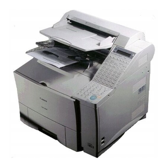
1.2 Configuration and Structure 1.2.1 Product names LASER beam printing type G3 facsimile FAX-L1000 1.2.2 External view PAPER FEED UNIT (option) FAX-L1000 Chapter 3: Technical Reference 508 mm 713 mm 828 mm 501 mm 571 mm Figure 3-1 External View HANDSET (option) - Page 148 FAX-L1000 Chapter 3: Technical Reference 1.2.3 Configuration a) Main unit Structural section Control section Scanning section Printing section Operation section Power supply Line interface section b) Accessories • Power Cord (UK, GER, FRN, AUS, AE only) • Document Feeder Tray •...
- Page 149 1.3 Specifications and Functions 1.3.1 Basic specifications Type Desktop facsimile transceiver Body color Art gray Power source Voltage Frequency Power consumption Standby (ESS On) Standby (ESS Off) Operation Maximum Main unit usage environment Temperature Humidity Horizontality Operating noise Measured in accordance with ISO standards Standby Operating Dimensions...
-
Page 150: Communications Specifications
FAX-L1000 Chapter 3: Technical Reference 1.3.2 Communications specifications Applicable lines Analog line (one line) • PSTN (Public Switched Telephone Network) Handset (Option) Handset with no numeric buttons Transmission method Half-duplex Transmission control protocol ITU-T V.8 protocol V.34 protocol/ECM protocol ITU-T T.30 binary protocol/ECM protocol Modulation method G3 image signals G3 procedure signals... - Page 151 Canon express protocol CEP1 Time required for transmission protocol Pre-message Mode Protocol V.8 / V.34 Approx. 6 s T.30 Standard Approx. 18 s CEP1 Approx. 9 s Time from when other facsimile is connected to the line until image transmission begins.
-
Page 152: Scanner Section Specifications
FAX-L1000 Chapter 3: Technical Reference 1.3.3 Scanner section specifications Type Sheets Sheet dimensions Maximum Minimum Thickness ADF capacity A4/Letter Legal B4 (AE only) 11 inch 17 inch Effective scanning width LTR/LGL B4 (AE only) Scanning method Contact sensor scanning method Scanning line density Horizontal: Standard/Fine/Superfine... - Page 153 Copy resolution Memory copy Scanning density adjustment Lighter, Standard, Darker: Scanning density adjustment is only valid in binary image mode. NOTE Image modes Binary Documents containing black-and-white characters Auto halftone Document containing black and white characters, documents containing photographs, mixed black and white characters, and photographs.
-
Page 154: Scanning Range
FAX-L1000 Chapter 3: Technical Reference Scanning range Item Effective 8.19"±0.004" scanning width (208 ±0.1 mm) Effective 11.54"±0.16" scanning length (293 ±4.0 mm) (Fine, Superfine) Effective 11.54"±0.22" scanning length (293 ±5.5 mm) (Standard) Left margin 0.04" ±0.12" (1.0 ±3.0 mm) Right margin 0.04"... -
Page 155: Printer Section Specifications
UPPER tray LOWER tray UPPER tray LOWER tray Printing method Laser beam printer Printing cartridge Product name Canon FX6 Toner Cartridge Product code H11-6431 Strage conditions Temperature Humidity Valid period 2.5 years from date of manufacture displayed on carton. Toner detection... - Page 156 FAX-L1000 Chapter 3: Technical Reference Recommended recording paper Canon Copier LTR/LGL Premium Paper Weight Paper size Manufactured by KANGAS Weight Paper size Manufactured by NEUSIEDLER Canon Paper Weight Paper size Manufactured by 75 g/m Letter, Legal BOISE CASCADE 80 g/m...
-
Page 157: Printing Range
Printing range Item Effective printing width Effective printing length Left margin Right margin Top margin Bottom margin margin Recording paper leading edge Recording paper trailing edge Figure 3-3 Printing Range FAX-L1000 Chapter 3: Technical Reference Letter 8.01 8.24" (203.5 mm) (209.4 mm) 11.34"... - Page 158 1.3.5 Functions FAX/TEL switching None Answering machine connection None Memory reception When receiving Canon FAX Standard Chart No.1 Standard Memory expanded Polling Polling transmission The document is accumulated into memory ahead of time, then transmitted when there is a polling request from the other party.
- Page 159 Auto dialing Telephone number digits One-touch dial Coded speed dial Group dial Redial Delayed transmission Locations Designated time Broadcast transmission Locations Group button addresses Relay broadcasting originating Group No. Subaddress (ITU-T standard) Transmission password (ITU-T standard) Destinations Relay broadcasting Group No. Subaddress (ITU-T standard) Transmission password (ITU-T standard)
- Page 160 FAX-L1000 Chapter 3: Technical Reference Activity management a) User report Activity management report (Every 40 transactions : Can be separated into Tx and Rx) Activity report (sending / receiving) 1-touch spd dial list Coded speed dial list Group dial list Memory clear list User’s data list Multi activity report...
- Page 161 Memory backup Backup contents Dial registration data, user data, service data, time Backup IC 512 kbit SRAM (256 kbit SRAM 2) Backup battery Lithium battery 3.0 V DC / 560 mAh Battery life Approx. 5 years Image data backup Backup contents Memory reception, memory copy, delayed transmission and broadcast transmission image data, activity management report...
-
Page 162: Theory Of Operations
FAX-L1000 Chapter 3: Technical Reference 2. THEORY OF OPERATIONS 2.1 Product Overview 2.1.1 Fax main unit This fax operates on ordinary AC230V household current, and has fax, telephone, and copy functions. The communication functions include 33.6k bps G3 transmission with ECM, contact scanner scanning with an ADF (auto document feeder) that can consecutively transmit multi-page documents, and a LASER beam printer that can print on plain paper. - Page 163 f) 4MB memory kit The image memory can be expanded by installing 4MB memory boards. Two memory boards can be installed in the fax machine. g) Verification stamp unit The verification stamp unit stamps a check mark near the trailing edge of the scanning side of each document to verify that all documents are transmitted correctly without any errors, such as double feeding.
- Page 164 FAX-L1000 Chapter 3: Technical Reference Main unit FAX-L1000 Option PAPER FEED UNIT PF-52 OPTION MEMORY VII (4MB) FAX-L1000 PostScript kit DUPLEX UNIT DU-52 ENVELOPE FEEDER EF-52 FAX-L1000 Printer kit STAMP UNIT RAM DIMM Module Consumables 16MB Figure 3-4 Product Overview 3-20 FAX-L1000 ISDN KIT FAX-L1000 Network Printer...
-
Page 165: Document And Recording Paper Flow
2.2 Mechanical Overview The mechanical section of this fax comprises the scanner section, the pickup section, and the printer section. 2.2.1 Unit layout diagrams a) Scanner section The scanner section has an ADF (auto document feeder) function and can automatically feed 50 sheets of A4 or letter size documents (20 sheets of B4 (AE only) or legal size documents). - Page 166 FAX-L1000 Chapter 3: Technical Reference Document path Scanner Section Printer Section Paper pickup Section Recording paper path Figure 3-5 Paper Path 3-22...
-
Page 167: Drive System Layout
2.2.3 Drive system layout a) Scanner section The power of the document read motor is transmitted by belt and gear to drive the pick-up, separation, feed, and eject rollers. The rotation of pick-up roller is controlled by a cam, DC motor and separation roller arm. - Page 168 FAX-L1000 Chapter 3: Technical Reference Read motor Document feed roller Document eject roller DC motor Read motor Document feed roller Paper feed roller Fixing eject roller Separation roller (Upper) Pressure roller Separation roller (Upper) Separation roller (Lower) Document eject roller Solenoid Main motor Pressure roller...
-
Page 169: Electrical System Layout
2.2.4 Electrical system layout a) Board layout a-1) SCNT board The SCNT board, which contains the system controller which controls the entire fax, is attached to the right side of the main unit. a-2) NCU board The NCU board, which controls the telephone line, is attached to the right side of the main unit behind the SCNT board. - Page 170 FAX-L1000 Chapter 3: Technical Reference Figure 3-7 Electrical System Layout ECNT board Power supply unit NCU board OPCNT board Sensor board Paper size detection boards SCNT board TWINS board Modular board Sensor board OPCNT board ECNT board Power supply unit Paper size detection board 1 Paper size detection board 2 TWINS board...
- Page 171 b) Sensor layout b-1) Contact sensor This contact sensor (CS) horizontally scans documents up to Letter size 8.42" (214mm) (B4 size 10.00" (254 mm) for AE) at a horizontal scanning resolution of 8 dots/mm. b-2) Document sensor (DS) This sensor, which detects the presence/absence of a document, is attached to the ADF section (Upper reader frame unit) sensor board.
- Page 172 FAX-L1000 Chapter 3: Technical Reference b-12) Recording paper eject sensor 1 This sensor, which detects whether or not the recording paper has been fed as far as the fixing unit, is attached to the ECNT board. b-13) Recording paper eject sensor 2 This sensor, which detects whether or not the recording paper has passed through the fixing unit, is attached to the fixing unit.
- Page 173 Document sensor Recording paper overload sensor 2 Recording paper overload release sensor Recording paper overload sensor 1 Recording paper eject sensor 2 Recording paper eject sensor 1 Figure 3-8 Arrangement of Sensors FAX-L1000 Chapter 3: Technical Reference Document width sensor Document feed sensor Document edge sensor Printer cover sensor...
-
Page 174: Document Feed Section
FAX-L1000 Chapter 3: Technical Reference 2.3 Scanner Section The scanner section comprises the document feed section and the optical section. 2.3.1 Document feed section a) Document feed function a-1) ADF (auto document feed) function The ADF feeds up to 50 pages separates each page with the separation roller (upper) and separation roller (lower), passes the page over the contact sensor unit, then ejects the paper to the document output tray. - Page 175 FAX-L1000 Chapter 3: Technical Reference Separation roller(upper) Pick-up roller Document path Separation roller(lower) Document feed roller Document eject roller Contact sensor Figure 3-9 Document Feed Section 3-31...
- Page 176 FAX-L1000 Chapter 3: Technical Reference Document stopper movement (1) When documents are set (Fig. A) The document stopper on the ADF section (Upper reader frame) stops the NOTE document which is inserted into the document insertion opening, preventing it from being pushed in too far. (2) When the stopper goes up (Fig.
- Page 177 FAX-L1000 Chapter 3: Technical Reference Figure 3-10 Stopper Movement 3-33...
- Page 178 FAX-L1000 Chapter 3: Technical Reference b-2) Document jam detection The document edge sensor detects such document jams as pickup jams and document too long errors. A “pickup jam” means the document edge sensor cannot detect the leading edge of the document within 15 seconds after document feeding begins.
-
Page 179: Optical Section
2.3.2 Optical section a) Functions a-1) Document scanning For document scanning, the Contact Sensor (CS) horizontally scans documents up to LTR size 8.42" (214mm)(B4 size 10.00" (254mm) for AE) at a horizontal scanning resolution of 8 dots/mm (Standard, Fine and Superfine) or 16 dots/mm (Ultrafine). Vertical scanning resolution is fixed by selecting resolution button on the operation panel. - Page 180 FAX-L1000 Chapter 3: Technical Reference b) Structures b-1) Contact sensor The contact sensor is designed to be dust-free, so that dust and other such minute particles cannot find their way inside the contact sensor housing, to settle on the sensor surface. The contact sensor consists of an LED array that emits light for scanning, a lens that distributes light from the LED array uniformly in the horizontal direction, a contact glass that refracts the light to the document, a rod lens array that receives the light reflected...
- Page 181 I n c i d e l i g h Incident light Scanning glass Photo transistor Figure 3-11 Contact Sensor FAX-L1000 Chapter 3: Technical Reference Document Contact sensor logic board Document Contact sensor logic board 3-37 Rod rens array Scanning glass Rod rens array...
- Page 182 FAX-L1000 Chapter 3: Technical Reference 2.4 Paper Load Section a) Functions a-1) Recording paper pickup function (From multi-purpose tray) In case of paper pick-up from the multi-purpose tray, while the main motor rotates, the multi-purpose tray pick-up solenoid is turned ON. Then, the multi-purpose pick-up roller rotates, and a sheet of paper is fed into the printer section.
- Page 183 b) Structures b-1) Cassette paper loading In case of paper pick-up from the cassette, while the main motor rotates, the pick-up solenoid (SL101) is turned ON. Then, cassette pick-up roller, cassette feed roller, separation roller and feed rollers rotate, and a sheet of paper is fed into the fax. In case of paper pick-up from the multi-purpose tray, while the main motor rotates, the multi-purpose tray pick-up solenoid (SL102) is turned ON.
- Page 184 FAX-L1000 Chapter 3: Technical Reference Lifting plate Figure 3-12 Cassette Paper Loading Spring Paper pickup roller 3-40 Paper pickup roller Feed roller Feed roller Separation roller Feed roller Separation roller...
- Page 185 b-2) Recording paper pickup jam detection configuration Recording paper pickup jams are detected by the photo-interrupter type recording paper pickup sensor equipped with an actuator arm. There are the following two types of recording paper pickup jams. Recording paper pickup jam 1 a.
- Page 186 FAX-L1000 Chapter 3: Technical Reference b-3) No recording paper detection configuration The presence of paper on the multi-purpose tray is detected by the multi-purpose tray paper sensor (PS105). No recording paper processing When a no recording paper error occurs in the side cassette, the main motor drive is stopped, print operations are stopped, the error is displayed on the display, and the Rec.
-
Page 187: Paper Feeder
FAX-L1000 Chapter 3: Technical Reference Paper size SW601 SW602 No cassette LEGAL LETTER SW600 SW601 SW602 Figure 3-13 Paper Size Detection Configuration (Paper feeder) Paper size SW801 SW802 SW803 No cassette LEGAL Executive LETTER Other Custom SW801 SW802 SW803 Figure 3-14 Paper Size Detection Configuration (Option paper feed unit PF-52) 3-43 SW603... -
Page 188: Printer Section
FAX-L1000 Chapter 3: Technical Reference 2.5 Printer Section The LASER beam printer engine comprises the following sections. Laser/Scanner unit Mirror Toner cartridge Fixing unit Feed belt ECNT board Transfer charging Feed roller roller Figure 3-15 Printer Section 3-44... -
Page 189: Paper Feed/Eject Section
2.5.1 Paper feed/eject section a) Functions a-1) Paper feed/eject The feed section feeds the recording paper fed from the pickup section to the toner transfer section and fixing unit. The eject section ejects the paper from the recording paper eject outlet on the main unit after printing. - Page 190 FAX-L1000 Chapter 3: Technical Reference Pre-transfer roller Photosenstive drum Feed belt Fixing eject roller Paper path Pressure roller ECNT board Feed roller Figure 3-16 Paper Feed/Eject Section 3-46...
- Page 191 b-2) Recording paper jam detection configuration Recording paper jams in the paper feed/eject section are detected by the photo-interrupter type pre-feed sensor, top of page sensor, recording paper eject sensor 1 and 2, which is equipped with an actuator arm. The CPU assesses a delivery delay jam if the recording paper eject sensor 1 (PS501) does not detect the leading edge of the paper within the specified period of time (T) after the top of page sensor (PS103) detects the leading edge of the paper.
-
Page 192: Laser/Scanner Section
FAX-L1000 Chapter 3: Technical Reference 2.5.2 LASER/Scanner section a) Functions Scanning mirror Focusing lens Mirror BD mirror Figure 3-17 LASER/Scanner Section The VIDEO signal (nVDO) is sent from the SCNT board to the laser driver of the laser/ scanner unit through the TWINS board and ECNT board. The laser driver turns the laser diode ON and OFF according to the nVDO signal and generates the modulated laser beam only when the VIDEO DATA ENABLE (nENBL) signal from the ECNT board is “L.”... - Page 193 b) Automatic power control of laser diode The laser driver IC conducts the automatic power control (APC) of the laser diode so that the laser diode emits a beam of constant intensity. When the FORCED LASER ON signal (nLON) becomes “L,” or the VIDEO DATA ENABLE signal (nENBL) and nVDO signal become “L,”...
-
Page 194: Toner Cartridge
FAX-L1000 Chapter 3: Technical Reference 2.5.3 Toner cartridge a) Functions Laser beam Primary charging roller Drum protective shutter Blade Developing cylinder Cleaner blade Photosensitive drum Figure 3-18 Toner Cartridge The image formation system is the central hub of the fax, and consists of the photosensitive drum, developing unit, charging rollers, etc. - Page 195 b) Electrostatic latent image formation block This block follows two steps to produce an electrostatic latent image on the photosensitive drum. When “Laser beam exposure” of this block is completed, negative charge remains in the unexposed “dark” areas; however, those in the exposed “light” areas are eliminated. This image of negative charges on the drum is invisible to the human eye, so it is called an “electrostatic latent image.”...
- Page 196 FAX-L1000 Chapter 3: Technical Reference b-2) Laser beam exposure Figure 3-21 Laser Beam Exposure When the laser beam scans the drum surface, it causes the charges in the areas struck by the laser beam to be neutralized. These areas on the drum surface form the electrostatic latent image.
- Page 197 As shown in Figure 3-23, the developing unit consists of a fixed magnet, a developing cylinder and a rubber blade. The developing cylinder rotates around the fixed imagnet. The single-component toner consists of magnetite and a resin binder, and is held to the cylinder by magnetic attraction.
- Page 198 FAX-L1000 Chapter 3: Technical Reference d-1) Drum cleaning Cleaner blade Photo- sensitive drum Waste toner case Sweeper strip Figure 3-24 Drum Cleaning The residual toner on the drum surface is scraped away with the cleaner blade to clean the drum surface in preparation for the next print. The removed waste toner is collected into the waste toner case.
- Page 199 FAX-L1000 Chapter 3: Technical Reference • The high-voltage terminal of the toner cartridge is shown below. High voltage terminal Figure 3-25 High Voltage Terminals • The AC bias applied to the developing cylinder during development is about 1600 Vp-p. • The DC bias applied to the developing cylinder during development changes with “SELECT DENSITY”...
-
Page 200: Transfer/Separation Section
FAX-L1000 Chapter 3: Technical Reference 2.5.4 Transfer/Separation section In this block, the toner image is transferred from the drum surface to the paper. a) Transfer Positive charges are applied to the back of the paper to attract the negatively charged toner particles to the paper. -
Page 201: Fixing Section
FAX-L1000 Chapter 3: Technical Reference 2.5.5 Fixing section As the toner image transferred onto the paper in the transfer block is only adhered by electrostatic attraction, even a light touch will smear the image. In the fixing block, the toner image is fixed by applying heat and pressure to the paper and the toner. - Page 202 FAX-L1000 Chapter 3: Technical Reference • This fax machine does not have "-ACVIN signal". • If the ECNT board CPU detects with the thermistor that the fixing heater temperature is over 428°F (220°C), it cuts off the power to the fixing heater (Software protection). •...
- Page 203 5. When the thermistor is in the high temperature detection mode and the initial temperature is 185°F(85°C) or more, it does not exceed about 320°F(160°C) (about 284°F(140°C) in case of 1200DPI) within about 6 seconds after the heater is turned ON. 6.
- Page 204 FAX-L1000 Chapter 3: Technical Reference 2.6 Circuit Overview 2.6.1 SCNT board function block diagram FAX-L1000 ISDN kit J700 J701 ECNT board Power supply unit CN22 Document feed motor Communication Speaker section control Operation control Document Drive control edge sensor Modular board J2(T1,T2) Modular...
- Page 205 2.6.2 Functions a) SCNT board The SCNT board performs the following functions. Drive control The drive control section controls the document feed motor in the document scanning section. Operation panel control The operation panel control section serially transfers data to or from the control IC on the OPCNT board, receives button operation status, document status, etc., and sends the display and LED signals to the control IC on OPCNT board.
- Page 206 FAX-L1000 Chapter 3: Technical Reference Memory functions User data, service data, data registered before shipment from the factory, and communications management information, are stored to the SRAM. Image data are stored to the DRAM. Memory backup The SCNT board is provided with a function for backing up data in control/image processing memory (SRAM) and image storage memory (DRAM) by lithium battery, and rechargeable battery, even if a power interruption occurs, or the power cord is disconnected by accident.
- Page 207 d) OPCNT board Buttons detection and LED drive function The control IC on the OPCNT board detects the buttons operation status, and drives the LCD and LEDs. Display The control IC in the LCD module controls the 20-column display signals from the SCNT board. Serial communication Serial communication with the SCNT board is used to send buttons, speaker volume switch, document status, etc., and to receive display, LED drive data, etc..
-
Page 208: Ecnt Board Function Block Diagra
FAX-L1000 Chapter 3: Technical Reference 2.6.3 ECNT board function block diagra SCNT board TWINS board Power supply unit Low-voltage, High-voltage power supply J201 Tonner cartridge Horizontal synchronization signal (-BD) control Fixing unit Recording paper eject sensor1 J103 Recording paper eject sensor2 2bin solenoid Figure 3-30 Function Block Diagram (2) - Page 209 FAX-L1000 Chapter 3: Technical Reference 2.6.4 Functions a) ECNT board Fixing heater control The fixing heater control section monitors the DC voltage supplied from the power supply in response to the AC 187~264 V, and the fixing heater thermistor, and drives the heater so that the temperature reaches the specified level.
- Page 210 FAX-L1000 Chapter 3: Technical Reference Toner detection Signals are received from the antenna type toner sensor, and monitors the remaining toner of the toner cartridge. b) Paper size detection board 1 Sensors The cassette recording paper size sensor (SW600,601,602), and cassette recording paper sensor for cassette1 are attached to the paper size detection board 1.
-
Page 211: Scnt Board Component Block Diagram
2.6.5 SCNT board component block diagram Address bus Data bus Control Signal etc. SCNT board Lithium RESET battery IC16 SRAM SRAM 256K 256K IC31 DRAM DRAM IC18 MM66364FP FUNC System controller 40MHz DC-DC Converter IC23 RESET Driver Rechargeable battery Button IC 1 BU6215KS GATE ARRAY... - Page 212 FAX-L1000 Chapter 3: Technical Reference a) System control section (SCNT board) The system control section consists of the following components and controls the entire facsimile system. a-1) MPU (Micro Processor Unit) (IC 17) The MPU, on NEC UPD70741GC-25-7EA, has the following main functions. •16-bit CPU •24-bit address bus •16-bit data bus...
- Page 213 a-4) DRAM (IC 3, 31) This 16-Mbit DRAM is backed up by rechargeable battery (approx. 12 hour after AC power interruption), and is used as memory for storing image data and MPU work area. a-5) SRAM (IC 5, 6) These 256-kbit SRAMs are backed up by lithium battery. SRAM holds data registered for system control and communications management information.
- Page 214 FAX-L1000 Chapter 3: Technical Reference b-2) CODEC IC (IC 22) The main functions of the CODEC IC are as follows: •Scanner interface •Serial interface to image processing IC •Encoder •Decoder •Printer interface •Serial interface port for the SCNT printer interface b-3) SRAM (IC 21) A 256-kbit SRAM is used as a buffer for the image processing data.
-
Page 215: Ecnt Board Component Block Diagram
2.6.6 ECNT board component block diagram FAX-L1000 Printer Kit(option) Cooling fan TWINS board 2bin solenoid Main motor Multi-purpose sensor ECNT board Recoding paper overload sensor 1 Recoding paper Recording paper overload sensor 2 eject sensor 1 Top of sensor IC502 Feed roller RESET clutch... - Page 216 FAX-L1000 Chapter 3: Technical Reference a) Printer control section (ECNT board) The printer control section consists of the following components and controls the LBP printer. a-1) Single chip microcomputer (IC 501) The single chip microcomputer has the following main functions. •8-bit CPU •24k-byte ROM •512k-byte RAM...
- Page 217 2.6.7 Flow of image signals a) G3 memory transmission (1) The image is scanned by the contact sensor, and the analog image data is sent to the SCNT board. (2) The image processing IC (IC20) converts the analog image data from the contact sensor into digital data.
-
Page 218: Contact Sensor
FAX-L1000 Chapter 3: Technical Reference IC22 IC26 SCNT board CONTACT SENSOR IC20 IC17 NCU board Figure 3-33 Transmission 3-74 A:Image processing IC B:CODEC IC C:DRAM D:MODEM IC E:System control IC F:Main CPU... - Page 219 b) G3 reception (1) The received image signal by L1, L2 is passed through a 2-line - 4-line conversion circuit in the NCU board, and amplified. The encoded data received by the MODEM IC (IC26) is read out by the CPU and then it is written into the DRAM (IC3) reception buffer by the CPU.
-
Page 220: Ncu Board
FAX-L1000 Chapter 3: Technical Reference IC22 IC18 IC26 SCNT board NCU board IC17 A:Image processing IC B:CODEC IC C:DRAM D:MODEM IC E:System control IC F:Main CPU Figure 3-34 Reception 3-76 Print out... -
Page 221: High-Speed Transmission
3. NEW FUNCTION 3.1 High-speed Transmission The image transmission time is reduced drastically compared with the previous models by the V.34 modem (maximum transmission speed 33600 bps) recommended by ITU-T. 3.1.1 V.8/V.34 protocol a) Outline • The V.8 protocol is used as the startup protocol to move to V.34. The V.8 protocol enables connection with fax machines, data modem and equipment using existing V-series modems. - Page 222 FAX-L1000 Chapter 3: Technical Reference 1. The V.34 protocol uses ECM. If the ECM SW in user data is set to OFF, the V.8 protocol is not executed. Therefore, the V.34 protocol is not used, and V.17 or a lower protocol is selected. NOTE 2.
- Page 223 b) Typical protocol Network interaction ANSam (Phase 1) INFO0c INFO0a Probing (Phase 2) INFO0h Primary channel equalizer training (Phase 3) Control channel start-up (Phase 4) flags Control channel flags "1" Primary channel resyncronization procedure Image data Image data Turn-Off Control channel resyncronization procedure (Communication end...
- Page 224 FAX-L1000 Chapter 3: Technical Reference b-1) Network interaction (Phase 1) The V.8 protocol is used as the startup protocol for high-speed modem V.34. The V.8 protocol determines the best modulation method (V-series modem mode) that is available between the transmitter and receiver. •...
- Page 225 b-2) Probing (Phase 2) The line characteristics are measured and modulation-related parameters, such as symbol rate, are set. • Transmitter Abbre- Signal viation INFO sequence INFO0c Tone B Tone B Probing signal Probing signal • Receiver Abbre- Signal viation INFO sequence INFO0a Tone A Tone A...
- Page 226 FAX-L1000 Chapter 3: Technical Reference b-3) Primary channel equalizer training (Phase 3) Filters, such as equalizers, are trained (adjusted) with the parameters set in phase 2. • Transmitter Signal S signal S signal PP signal TRN signal b-4) Control channel start-up (Phase 4) Select the maximum data signalling rate and trellis encoder and set the data signalling rate that can be supported.
- Page 227 b-5) Control channel The conventional T.30 protocol is executed. The transmission speed is 600bps. • Transmitter Abbre- Signal viation Flag flags Non-standard facilities set-up Transmitting subscriber identification Digital command signal ——— • Receiver Abbre- Signal viation Non-standard facilities Called subscriber identification Digital identification signal...
- Page 228 FAX-L1000 Chapter 3: Technical Reference b-6) Primary channel resyncronization procedure Training is performed with the parameters set in phase 4. The transmission speed is 1200bps. • Transmitter Signal S signal S signal PP signal Sequence B1 b-7) Image data Transmit image data. •...
- Page 229 b-8) Control channel resyncronization procedure (Communication end procedure) Protocol for terminating transmission. The transmission speed is 1200bps. • Transmitter Abbre- Signal viation Sh signal Sh signal ALT signal E sequence End of procedures PPS-EOP Flag flags Disconnect signal • Receiver Abbre- Signal viation...
- Page 230 FAX-L1000 Chapter 3: Technical Reference c) Examples of sequences The signals in the shaded areas are important in the protocol. c-1) Late start Since the receiver cannot detect the CM signal while sending the ANSam signal, it sends the DIS signal containing the "V.8 protocol" declaration. The transmitter sends the CI signal to request the receiver to send the ANSam signal again to move to V.8 protocol.
- Page 231 c-2) Between-page sequence The transmitter sends image data, then the PPS-MPS signal in the same as for the T.30 protocol. The receiver sends the MCF signal to receive the next page. Figure 3-37 Between-page Sequence FAX-L1000 Chapter 3: Technical Reference Image data Turn-off...
- Page 232 Mode change The transmitter sends PPS-EOM and the receiver sends the MCF signal. Then the receiver sends the DIS signal and the transmitter sends the DCS signal to change the mode. When Canon fax machines communicate with each other, a special procedure is used, so this protocol is omitted.
- Page 233 c-4) Image transmission speed change from the receiver The receiver returns to the PPh signal in response to the Sh signal from the transmitter. The image transmission speed is then determined by the MPh sequence sent from both modems. Figure 3-39 Image Transmission Speed Change from the Receiver FAX-L1000 Chapter 3: Technical Reference Image...
- Page 234 FAX-L1000 Chapter 3: Technical Reference c-5) Image transmission speed change from the transmitter The transmitter sends image data, and then the PPh signal, and the receiver returns the PPh signal to the transmitter. The image transmission speed is then determined by the MPh sequence sent from both modems.
- Page 235 3.2 JBIG Image Compression Encoding Method 3.2.1 Outline of the JBIG Image Compression Encoding Method The JBIG Image Compression Encoding Method is recommended in ITU-T T.82/T.85 as a new bi-level (bi-level: White and Black) image compression encoding method developed by JBIG (Joint Bi-level Image experts Group).
-
Page 236: Single Progression Sequential Bi-Level Image Compression Method
FAX-L1000 Chapter 3: Technical Reference The characteristics of Progressive Bi-level Image Compression are explained below as a reference. First of all, after the original image has been read in at high resolution, it is converted to low resolution, and this low resolution NOTE image data proceeds to be encoded (compressed). -
Page 237: Encoding Method
3.2.3 Encoding Method In the JBIG encoding used in the Single Progression Sequential Bi-level Image Compression Method, uses in the encoder shown below to encode to the original the results of comparison of the line currently being processed and the previous line, as well as the predicted value of an image pixel (white or black) used in a model template. - Page 238 FAX-L1000 Chapter 3: Technical Reference b) In the model template, the combination (10-bit pixel pattern) of 10 pixels is output to the arithmetic encoding section using the template shown below (inside the bold outline). All of the 10-bit pixel patterns inside this template exist in the study table. This 10-bit pixel pattern is used by the arithmetic encoding section to refer to the predicted value of the pixel and the status number in the study table which correspond to the 10-bit pixel pattern.
- Page 239 3-line model template Figure 3-44 Positions of Pixels in Model Template Table 3-1 Study Table (Initial values) Pixel pattern in the model template 000h 001h 002h 003h 004h 005h 3FBh 1019 3FCh 1020 3FDh 1021 3FEh 1022 3FFh 1023 Table 3-2 Probability Estimation Table NLPS NMPS SWITCH...
- Page 240 FAX-L1000 Chapter 3: Technical Reference Example: A brief explanation of how the study table works is given below. It is assumed that each of the model template pixels 1~10 in the image below are white. 1. In this case, the model template pixel pattern is 000h. 2.
- Page 241 d) The probability estimation table, published in the ITU-T T.82. Its contents are fixed, differing from those of the study table. This table shows probability of accuracy/inaccuracy in the form of a range, according to the accurate/inaccurate results of a given status prediction value. The plan of the probability estimation table is such that if the prediction is NOTE accurate, the range of the next status number will be smaller than would be...
- Page 242 FAX-L1000 Chapter 3: Technical Reference The concept of arithmetic encoding is simply explained below. The following assumptions are made in order to make the explanation easy to understand. The probability of accuracy will be 50%, and the probability of inaccuracy will be 50%.
- Page 243 Next, the encoding for continuous accurate predictions will be simply explained. The assumptions below will be made for easy understanding. The value of an accurate LSZ will be decimal 100 Range A will have limits of decimal 8000~10000 8000 , the lead encoding bit will be pushed out, and the encoded image data will be output.
-
Page 244: Construction Of Image Data With Jbig Image Compression Encoding
FAX-L1000 Chapter 3: Technical Reference 3.2.4 Construction of image data with JBIG Image Compression Encoding Images are encoded in block units called stripes, as shown in the figure below. Document width (XD) Document length (YD) Document Figure 3-49 Construction of JBIG Image Data After being encoded, the image data is referred to as BIE (Bi-level Image Entity), and is constructed from the Bi-level Image Header (BIH) section and the Bi-level Image Data (BID) section shown in the figure below. -
Page 245: Explanation Of Bi-Level Image Header Section (Bih)
3.2.5 Explanation of Bi-level Image Header section (BIH) The BIH is shown in the construction figure below. It designates the image size, number of lines per stripe, model template, etc. FILL 1byte 1byte 1byte 1byte 1bit 1bit 1bit 1bit Figure 3-51 BIH Construction Diagram FAX-L1000 Chapter 3: Technical Reference BIH (Bi-level Image Header) 4byte... -
Page 246: Explanation And Parameters For Each Symbol Used In Bih
FAX-L1000 Chapter 3: Technical Reference 3.2.6 Explanation and parameters for each symbol used in BIH The 0x of each parameter shows that the following integers are hexadecimal. Symbol Initial layer to be transmitted Number of differential layers Number of bit planes FILL Fill Horizontal image size at layer D... -
Page 247: Explanation And Parameters For Each Symbol Used In Bid
3.2.7 Explanation of Bi-level Image Data (BID) section BID is as shown in the construction figure below, and consists only of the number of stripes. BID is constructed by the connection of the floating marker code and the section which includes the actual image data encoded with JBIG image compression encoding, called SDE (Stripe Data Entity). - Page 248 FAX-L1000 Chapter 3: Technical Reference COMMENT (Private comment: 0x07) An optional comment may be added. ESC 0x07 Lc:Comment length NEWLEN (New length: 0x04) Redefine the document length. Only usable when VLENGTH=ON. ESC 0x04 YD:Document length RESERVE (Reserve: 0x01) Only usable for characteristic use. ESC 0x01 b) Stripe data section PSCD (Protected stripe encoding data)
-
Page 249: Energy Save Standby (Ess)
3.3 Energy Save Standby (ESS) a) Function ESS is an energy save function for minimizing power loss during standby. During ESS, the ESS control section of the system control IC inside the SCNT board halts all oscillators other than the real time clock (RTC) IC in order to reduce power loss. Because of this, the operation of ICs etc. - Page 250 FAX-L1000 Chapter 3: Technical Reference The power consumption at standby is 22 W in non-ESS mode and 2 W in ESS mode. The ESS function does not operate when the FAX-L1000 ISDN Kit or NOTE FAX-L1000 Printer Kit are installed. b) Operation The ESS function sets the main unit to the ESS mode if the next operation is not carried out within about three minutes after the main unit ends transmission, reception, or copying.
- Page 251 Chapter 4 Maintenance and Service...
-
Page 253: Maintenance
Cooling fan Please use “Shachihata X Stamper Inks CS-20 Yellow (H12-3372)” for the stamp. Recommended recording paper is shown below. NOTE Canon Copier LTR/LGL Premium Paper Weight Paper size Manufactured by FAX-L1000 Chapter 4: Maintenance and Service When When “INSTALL CARTRIDGE”... - Page 254 FAX-L1000 Chapter 4: Maintenance and Service KANGAS Weight Paper size Manufactured by NEUSIEDLER Canon Paper Weight Paper size Manufactured by Consumable parts are expected to require replacement at least once during the warranty period of this fax, due to deterioration or damage. The life span of...
- Page 255 1.1.2 Cleaning Level Location User Main unit outer cover Document pick-up roller Document separation roller (upper) Document separation roller (lower) Document feed roller Document eject roller Scanning glass White sheet unit Transfer guide (upper and lower) FAX-L1000 Chapter 4: Maintenance and Service When When dirty.
- Page 256 FAX-L1000 Chapter 4: Maintenance and Service Level Location Service technician Multi-purpose tray pick-up roller Cassette pick-up roller Cassette separation roller Cassette feed roller Separation pad Feed roller Pre-transfer roller Registration arm Transfer guide (upper and lower) Transfer charging roller Paper feed belt Paper feed guide Fixing entrance guide Fixing film...
-
Page 257: Periodic Replacement Parts
Level Location Fixing pressure roller Fixing eject roller Face-up deflector Lower paper delivery guide 1.1.3 Periodic inspections Level Location User None Service technician None 1.1.4 Periodic replacement parts Level Location User None Service technician None FAX-L1000 Chapter 4: Maintenance and Service When When marks on back of recording paper at intervals of 2.48"... -
Page 258: Special Tools
FAX-L1000 Chapter 4: Maintenance and Service 1.2 Tools 1.2.1 General tools Tool Phillips screwdriver Slot head screwdriver Precision phillips screwdriver Precision slot head screwdriver Tweezers Pliers, needle nose Digital volt meter Lint-free paper Isopropyl alcohol Ruler 1.2.2 Special tools Tool Grease (TELLUS OIL 68) Grease (MOLYKOTE EM-50L) Grease (FLOIL GE676) -
Page 259: Consumables Replacement
2. CONSUMABLES REPLACEMENT 2.1 Toner Cartridge For details on how to replace the toner cartridge, see Chapter 5: 1.4 Assembling the Fax . REFERENCE 2.2 Recording Paper For details on how to refill the paper, see Chapter 5, 1.4 Assembling the Fax . -
Page 260: Stamp Ink
FAX-L1000 Chapter 4: Maintenance and Service 2.3 Stamp Ink Disconnect the power cord of the fax unit from its power source. Lift the document feeder tray, and gently open the ADF cover until it stops, grasping the document feeder tray and the ADF cover at the same time. - Page 261 FAX-L1000 Chapter 4: Maintenance and Service Gently lift the ADF cover up to the full open position. Figure 4-2 Refilling the Stamp Ink 2 Locate the stamp pad then apply only one drop of ink to the stamp ink compartment. To avoid a malfunction, do not add too much ink.
- Page 262 FAX-L1000 Chapter 4: Maintenance and Service Close the ADF cover, lower the document feeder tray, and connect the power cord of the fax unit to the power source. • Make sure that you do not drip ink on any other part of the fax. •...
-
Page 263: Scanning Glass (Contact Sensor)
3. CLEANING 3.1 Main Unit Wipe any dirt off with a soft, dry cloth. 3.2 Document Pick-up Roller Open the upper reader frame unit and wipe any dirt off with a soft, dry cloth. 3.3 Separation Roller (Upper) Open the upper reader frame unit and wipe any dirt off with a soft, dry cloth. 3.4 Separation Roller (Lower) Open the upper reader frame unit and wipe any dirt off with a soft, dry cloth. - Page 264 FAX-L1000 Chapter 4: Maintenance and Service Document pick-up roller White Sheet Scanning Glass Do not use tissue. Otherwise, paper dust may stick to the parts or a static charge may be generated. In cases where there is a lot of dirt in item 3.1, polish with a cloth after wiping off the dirt with a cloth wet with water and wrung out.
-
Page 265: Transfer Guide
3.10 Transfer Guide a) Preparations for cleaning (1) Disconnect the power cord of the fax from the power source. (2) Lift the document feeder tray, the document output tray and the upper output tray. Figure 4-6 Preparation for Cleaning 1 (3) Open the printer cover and remove the toner cartridge. - Page 266 FAX-L1000 Chapter 4: Maintenance and Service b) Cleaning (1) Using a soft clean cloth, wipe any paper dust off the black plate of the transfer guide. Transfer guide (2) While holding the green lever, flip the transfer guide up. Wipe the edge of the transfer guide with a soft, clean cloth, to remove toner and paper dust from both sides of the transfer guide.
- Page 267 FAX-L1000 Chapter 4: Maintenance and Service (3) Pull the transfer guide back to its full extent, then wipe the silver metal strip with cloth. Then gently guide the transfer guide back to its original position. Transfer charging roller Figure 4-10 Cleaning Location 3 The spring for the transfer guide is strong.
-
Page 268: Transfer Charging Roller
FAX-L1000 Chapter 4: Maintenance and Service 3.11 Transfer Charging Roller a) Preparations for cleaning (1) Disconnect the power cord of the fax from the power source. (2) Lift the document feeder tray, the document output tray and the upper output tray. (3) Open the printer cover and remove the toner cartridge. - Page 269 b) Cleaning (1) Using lint-free paper, wipe any dirt off the transfer charging roller. Hold the shaft. Figure 4-12 Cleaning Location Do not touch or hold the rubber section of the transfer charging roller. Doing so can cause marks on back of paper or blank spots in copied or received images. NOTE Never clean with solvents! If lint-free paper can not fully clean the transfer charging roller or if the roller is...
-
Page 270: Cassette Pick-Up Roller/Feed Roller/Separation Roller
FAX-L1000 Chapter 4: Maintenance and Service 3.12 Cassette Pick-Up Roller/Feed Roller/Separation Roller a) Preparations for cleaning (1) Disconnect the power cord of the fax from the power source. (2) Disconnect the telephone line mojular jack cord. (3) Remove the document feeder tray, the document output tray, the upper output tray and the cassettes. - Page 271 b) Cleaning (1) Using lint-free paper dipped in alcohol, wipe any dirt off the cassette pick-up roller and the cassette feed roller while rotating the shaft in the indicated direction. Figure 4-15 Cleaning Location 1 (2) If a paper feed unit PF-52 is installed, cleaning the option by the same way in the above step (1).
-
Page 272: Multi-Purpose Tray Pick-Up Roller/Separation Pad
FAX-L1000 Chapter 4: Maintenance and Service 3.13 Multi-Purpose Tray Pick-Up Roller/Separation Pad a) Preparations for cleaning (1) Disconnect the power cord of the fax from the power source. (2) Open the multi-purpose tray. (3) Remove the entrance cover. Figure 4-17 Preparation for Cleaning 1 (4) Remove the multi-purpose tray pick-up roller, after release the claw with rotating the slot head screw driver. - Page 273 b) Cleaning (1) Using lint-free paper dipped in alcohol, wipe any dirt off the multi-purpose tray pick-up roller. Multi-purpose tray pick-up roller Figure 4-19 Cleaning Location 1 (2) Using lint-free paper dipped in alcohol, wipe any dirt off the multi-purpose tray separation pad.
-
Page 274: Feed Roller
FAX-L1000 Chapter 4: Maintenance and Service 3.14 Feed Roller a) Preparations for cleaning (1) Disconnect the power cord of the fax from the power source. (2) While holding the upper reader frame and the middle reader frame open with one hand, use one finger of your other hand to gently push in the stopper to separate it from the stub on the fax machine, and open the upper reader frame and the middle reader frame. - Page 275 (4) Remove the right cover, front right cover, rear cover and the read motor cover. (5) Remove the joint of the printer cover using the needle nose prier and release the claw using the precision slot head screw driver. Then, remove the printer cover. Printer cover Release the claw inside using the precision slot...
- Page 276 FAX-L1000 Chapter 4: Maintenance and Service (10) Remove the shield cover and the operation panel. Figure 4-25 Preparation for Cleaning 5 (11) Remove the PCBs and the metal frame. Then, disconnect the solenoid connector. Solenoid connector Figure 4-26 Preparation for Cleaning 6 Operation panel Shield cover Metal frame...
- Page 277 (12) Remove the entrance cover. (13) Disconnect the multi-purpose paper sensor cable. Multi-purpose paper sensor cable Figure 4-27 Preparation for Cleaning 7 (14) Remove the two long screws. (15) Remove the one screw of the envelope feeder gear cover. Then, push the claw from the inside and remove the envelope feeder gear cover.
- Page 278 FAX-L1000 Chapter 4: Maintenance and Service b) Cleaning (1) After removing the envelope feeder gear cover and the multi-purpose pick-up ass’y, using lint-free paper dipped in alcohol, wipe any dirt off the feed roller while rotating the gear. The gears should always be greased. If the grease is lost, reapply to them. Gear Multi-purpose pick-up ass'y Envelope feeder gear cover...
-
Page 279: Pre-Transfer Roller And Registration Arm
3.15 Pre-Transfer Roller and Registration Arm a) Preparations for cleaning (1) Refer to 3.14 Feed Roller to remove the envelope feeder gear cover and the multi- purpose pick-up ass’y. (2) Remove the six screws. Figure 4-30 Preparation for Cleaning 1 (3) Remove the front inner cover ass’y. - Page 280 FAX-L1000 Chapter 4: Maintenance and Service b) Cleaning (1) Using lint-free paper dipped in alcohol, wipe any dirt off the pre-transfer roller and registration arm. The gear should always be greased. If the grease is lost, reapply to it. Registration arm Gear Pre-transfer roller Figure 4-32 Cleaning Location...
-
Page 281: Paper Feed Belt And Paper Feed Guide
3.16 Paper Feed Belt and Paper Feed Guide a) Preparations for cleaning (1) Refer to 3.11 Transfer Charging Roller to remove the transfer charging roller. (2) Remove the paper feed roller using the precision slot head screwdriver. When removing the paper feed roller, do not make contact with the static charge eliminator. - Page 282 FAX-L1000 Chapter 4: Maintenance and Service (2) Using lint-free paper dipped in alcohol, wipe any dirt off the paper feed guide. Paper feed guide Figure 4-35 Cleaning Location 2 4-30...
-
Page 283: Fixing Unit Entrance Guide
3.17 Fixing Unit Entrance Guide a) Preparations for cleaning (1) Disconnect the power cord of the fax from the power source. (2) Remove the right rear cover and the left rear cover. (3) Remove the face-up tray. (4) Loose the two screws and remove the fixing ass’y. Screw Right rear cover Fixing ass'y... -
Page 284: Fixing Film
FAX-L1000 Chapter 4: Maintenance and Service 3.18 Fixing Film a) Preparations for cleaning (1) Disconnect the power cord of the fax from the power source. (2) Refer to 3.17 Fixing Unit Entrance Guide to remove the fixing ass’y. (3) While pushing the claw, remove the left fixing ass’y connector. Figure 4-38 Preparation for Cleaning 1 When remove the connector, be careful not to scratch the cable with the edge of metal chassis. - Page 285 FAX-L1000 Chapter 4: Maintenance and Service (4) Remove the upper crossmember. Upper crossmember Figure 4-40 Preparation for Cleaning 3 b) Cleaning (1) Using lint-free paper, wipe any dirt off the fixing film. Fixing film Figure 4-41 Cleaning Location When cleaning, be careful not to touch the fixing film. NOTE 4-33...
-
Page 286: Face-Up Deflector, Fixing Delivery Roller And Lower Paper
FAX-L1000 Chapter 4: Maintenance and Service 3.19 Face-Up Deflector, Fixing Delivery Roller and Lower Paper Delivery Guide a) Preparations for cleaning (1) Disconnect the power cord of the fax from the power source. (2) Refer to the Figure 4-36, 4-37 and 4-40 to remove the upper crossmember. (3) Remove the upper paper guide ass’y. -
Page 287: Parts Replacement
4. ADJUSTMENT 4.1 Parts Replacement Please refer to the separate PARTS CATALOG for disassembly / assembly procedures to follow when replacing parts. The PARTS CATALOG shows illustrations which follow the disassembly procedures. Additionally, there are enlarged and special-help illustrations for parts which require caution during disassembly and assembly. -
Page 288: Leading Edge Margin Adjustment
FAX-L1000 Chapter 4: Maintenance and Service 4.4 Leading Edge Margin Adjustment a) When As VR501 on the ECNT board is adjusted at the factory, its adjustment at the time of installation is not required. However, when the ECNT board is replaced in the field, the leading edge margin needs to be readjusted. - Page 289 (7) Make several test prints again, and perform step (5). Check that the leading edge margin is 2.0mm. If the value is incorrect, repeat steps (4) to (7). VR501 SW501 Clockwise Counterclockwise Leading edge of paper Figure 4-44 Leading Edge Margin Adjustment FAX-L1000 Chapter 4: Maintenance and Service Turning one scale increases the leading edge margin approx.
-
Page 290: Precautions For Troubleshooting
FAX-L1000 Chapter 4: Maintenance and Service 5. TROUBLESHOOTING 5.1 Troubleshooting 5.1.1 Repairs a) Check installation environment Check that the following conditions have been met with regard to installation environment. (1) This fax must be installed on a level surface. (2) Ambient temperature should be 50°F (10°C) to 90.5°F (32.5°C), with humidity from 20 to 80%RH. - Page 291 5.2 Error Shown on the Display 5.2.1 User error message "# ALREADY IN USE" Cause: The box specified with confidential or polling communications is already in use. Solution: Change the setting or select another box. "AUTO REDIAL" Cause: The other party’s line was busy on the previous dialing attempt and the fax unit is dialing the number again.
- Page 292 FAX-L1000 Chapter 4: Maintenance and Service "CHECK POLLING ID" (#0008, #0021) Cause: Polling was impossible because the polling ID or your subaddress/password did not match. Solution: Check the polling ID or subaddress/password with the other party and try polling again. "CHECK PRINTER"...
- Page 293 "ENTER DAC" Cause: The department access code is not entered to send document. Solution: Enter the department access code. "HANG UP PHONE" Cause: The handset was left off the hook after the completion of transmission or reception. Solution: Put the handset back on the handset rest. "MEMORY FULL"...
- Page 294 FAX-L1000 Chapter 4: Maintenance and Service "NO RX PAPER" (#0012) Cause: Declares that the other fax has no recording paper for DIS. Solution: Contact the other party and have them load paper into their fax. "NO TEL#" (#0022) Cause: No one-touch speed dialing, coded speed dialing, or group dialing telephone number is registered.
- Page 295 "REC. PAPER JAM" (#0009) Cause: Recording paper jam This is displayed when the pre-feed sensor or the fixing unit delivery sensors 1&2 detects a paper jam. Solution: Recover paper jam. "RECEIVED IN MAILBOX" Cause: A confidential document has arrived in a mailbox of the fax unit, and the message will remain displayed until you print the document.
- Page 296 FAX-L1000 Chapter 4: Maintenance and Service "STOP KEY PRESSED" Cause: You have pressed the Stop button to cancel the current transaction. Solution: No need. "SUBADDRESS TX REJECTD" Cause: You attempted to send a document with an ITU-T subaddress, but the other party’s fax unit does not support receiving a document with an ITU- T subaddress.
-
Page 297: Error Codes
5.2.2 Error codes a) Service error code output If Service Data #1 SSSW SW01 bit 0 is set to “1”, then service error codes are printed on the activity management reports, reception result reports, error transmission reports, and system dump lists when communication ends in an error. Also, the following is displayed on the display when an error occurs. - Page 298 FAX-L1000 Chapter 4: Maintenance and Service •Echo measures Change the following bit switches of service data #1SSSW SW03. Bit 4 1: Ignore the first DIS signal sent by the other fax machine. 0: Not to ignore the first DIS signal sent by the other fax machine. Bit 5 1: Transmit a tonal signal (1850 or 1650 Hz) when the other fax machine sends a DIS signal.
- Page 299 c) Error code list The error codes used for this fax are as follows. Codes listed as “New” in the list below indicate new error codes, or codes whose measures differ from those listed in the separate document G3 Facsimile Error Code List (Rev.1) . For recovery methods for error codes indicated as “New”, see the item d) Recovery methods for codes indicated as “New”...
- Page 300 FAX-L1000 Chapter 4: Maintenance and Service Tx or Rx #0995 [ TX/RX ] c-2) Service error codes • G3 mode error codes Tx or Rx ##0100 [ TX ] ##0101 [ TX/RX ] ##0102 [ TX ] ##0103 [ RX ] ##0104 [ TX ] ##0106...
- Page 301 Tx or Rx ##0290 [ TX ] • Printer error codes Tx or Rx New ##0322 [ RX ] New ##0323 [ RX ] New ##0324 [ RX ] New ##0325 [ RX ] • V.8/V.34 protocol error codes Tx or Rx New ##0670 [ TX ] New ##0671...
- Page 302 FAX-L1000 Chapter 4: Maintenance and Service • ECM mode error codes Tx or Rx ##0750 [ TX ] ##0752 [ TX ] New ##0753 [ TX ] ##0754 [ TX ] ##0755 [ TX ] ##0757 [ TX ] New ##0758 [ TX ] ##0759 [ TX ]...
- Page 303 Tx or Rx Definition ##0770 [ TX ] Exceed repeat protocol limit due to failure to receive significant signals after transmitting EOR-NULL during ECM transmission ##0772 [ TX ] Receive DCN after EOR-NULL transmission during ECM transmission New ##0773 [ TX ] Exceed protocol retransmission limit or T5 time (60 seconds) after EOR-NULL transmission during ECM transmission...
- Page 304 FAX-L1000 Chapter 4: Maintenance and Service Tx or Rx ##0792 [ RX ] ##0793 [ RX ] ##0794 [ TX ] ##0795 [ TX/RX ] ##0799 [ TX ] Definition Fail to detect PPS-NULL between partial pages during ECM reception Time over due to failure to receive valid frame during high speed signal reception upon ECM reception Receive all 0 PPR during ECM transmission...
- Page 305 d) Recovery methods for codes indicated as “New” d-1) User error codes #0001 [TX] Paper jam Cause: The document jammed in the fax machine. Solution: Remove the document and transmit/copy again. Cause: The document width size or thickness does not meet the standards. Solution: Use a copy machine to copy the document to LTR or other standard size paper, then transmit that copy.
- Page 306 FAX-L1000 Chapter 4: Maintenance and Service Cause: Internal structure defect Solution: (1) Check if the document edge sensor (DES) is operating correctly using the methods given in Chapter 2: 2.4.7 Faculty tests , Test Mode [6] Faculty Test, [3] Sensor Tests. (2) Check the document edge sensor (DES) and SCNT board (J14) connections.
- Page 307 #0009 [RX] Recording paper jam or out of paper Cause: The recording paper jammed. Solution: Clear the recording paper jam. Cause: There is no recording paper. Solution: Load recording paper. Cause: Internal structure defect Solution: (1) Check if the cassette recording paper sensors, cassette recording paper size sensors, multi-purpose tray paper sensor, recording paper eject sensor are operating correctly using the methods given in Chapter 2: 2.4.7 Faculty tests , Test Mode [6] Faculty Test, [3] Sensor Tests.
- Page 308 FAX-L1000 Chapter 4: Maintenance and Service (21) Check the recording paper eject sensor 2, the cable and the fixing unit (J131) connections. (22) Replace the recording paper eject sensor 2. (23) Replace the ECNT board. (24) Replace the ECNT board. (Recording paper eject sensor 1 defect) #0021 [RX] DCN received during polling reception Cause: No subaddress/password set in other machine.
- Page 309 #0059 [TX] The number you dial and connected number (CSI) does not match Cause: “USER TEL” on the reception side not programmed, or wrongly programmed. Solution: (1) Contact reception side and check whether “USER TEL” has been properly programmed. (2) Check that the designated other party is connected, and transmit manually.
- Page 310 FAX-L1000 Chapter 4: Maintenance and Service #0099 [TX/RX] Pressed stop button during communication Cause: The Stop button was pressed during communication. Solution: Try transmit or receive again. #0102 [TX] In transmission, DCN received in response to password/sub- address Cause: Password/subaddress does not match. Solution: Contact the other party and have them set a password/subaddress.
- Page 311 d-2) Service error codes • Printer error codes ##0322 [RX] Fixing heater temperature abnormality Cause: Your fax is connected to a UPS (Uninterruptable Power Supply). Solution: Remove the UPS. Cause: Internal unit defect Solution: (1) Check fixing heater (J133, J134), the cables and the ECNT board (J31) connections.
- Page 312 FAX-L1000 Chapter 4: Maintenance and Service • V.8/V.34 protocol error codes ##0670 [TX] At V.8 late start, the called party declares the V.8 protocol in DIS signal and this unit transmits a CI signal, but the protocol does not progress and a T1 time-out occurs. Cause: The other party disconnected the line while the CI signal was being transmitted, or ANSam/DIS from the called party was not able to be...
- Page 313 ##0675 [RX] The protocol did not move from phase 3 to phase 4 and a T1 time-out occurred during V.34 reception. Cause: The transmitter disconnected the line during phase 3 or the signal from the transmitter was not able to be detected. Solution: Increase #2 MENU No.07 transmission level within a range of -8~-15 (dBm) or set #1 SSSW SW-28 bit 1 to "1"...
- Page 314 FAX-L1000 Chapter 4: Maintenance and Service • ECM mode error codes ##0753 [TX] Exceed protocol retransmission limit or T5 time (60 seconds) after PPS-NULL transmission during ECM transmission Cause: The other fax’s page buffer is full or is being used, so PPS- NULL was transmitted, then RNR was received and after RR transmission, no significant signals could be received.
- Page 315 ##0773 [TX] Exceed protocol retransmission limit or T5 time (60 seconds) after EOR-NULL transmission during ECM transmission Cause: The other fax’s page buffer is full or is being used, so EOR-NULL was transmitted, then RNR was received and after RR transmission, no significant signals could be received.
-
Page 316: Errors Not Shown On The Display
FAX-L1000 Chapter 4: Maintenance and Service 5.3 Errors not Shown on the Display a) No power Solution: (1) Plug in the power cord. (2) Check the fuse in the power supply unit. If the fuse (F1, F2) blows, replace the fuse. (3) Check the power supply and ECNT board (J101) connections. - Page 317 Document read motor does not run at all or dose not run normally Solution: (1) Make a copy, and make sure that the document read motor is operating correctly. (2) Check the SCNT board (J4) and document read motor connections. (3) Replace the document read motor.
- Page 318 FAX-L1000 Chapter 4: Maintenance and Service Vertical black band in images Solution: (1) Clean the white sheet of the middle reader frame unit. (2) Clean the scanning glass. (3) Set SSSW #1 SW06 Bits 0 and 1 to "1", as explained in the separate document G3 Facsimile Service Data Handbook (Rev.
- Page 319 g) Print defects Light Dark Dots Marks on back of paper Irregular and smudged black horizontal lines White vertical lines White horizontal lines Distortion -BD failure Figure 4-46 Faulty Print Samples FAX-L1000 Chapter 4: Maintenance and Service Completely blank Black vertical lines Marks Faulty...
- Page 320 FAX-L1000 Chapter 4: Maintenance and Service Light Solution: (1) In user data, set “SELECT DENSITY” of “FAX’S PRINTER SET” to “DK”. (2) Replace the toner cartridge. (3) During printing, open the printer cover, remove the toner cartridge, open the toner cartridge drum protective shutter by hand, and check that the toner image on the photosensitive drum is transferred to the recording paper.
- Page 321 All black Solution: (1) Clean the high-voltage terminal and the toner cartridge contact. (2) Replace the toner cartridge. (3) Replace the ECNT board. Dots Solution: (1) Clean the static charge eliminator with brush. (2) Clean the transfer charging roller. (3) Clean the transfer charging roller shaft contact. (4) Check the contact between the static charge eliminator and the ECNT board.
- Page 322 FAX-L1000 Chapter 4: Maintenance and Service Black vertical lines Solution: (1) Clean the mirror. (2) During printing, open the printer cover, remove the toner cartridge drum protective shutter by hand, and check if there are vertical black lines on the photosensitive drum. (3) If there are vertical black lines on the photosensitive drum, replace the toner cartridge.
- Page 323 Marks Solution: (1) Copy a few white paper documents. (2) If the marks is at intervals of approx. 3.70" (94 mm), replace the toner cartridge. (3) If the marks is at intervals of approx. 2.97" (75 mm), clean the cassette separation roller.
- Page 324 FAX-L1000 Chapter 4: Maintenance and Service Faulty registration Solution: (1) Check if more than the regulation amount of recording paper is loaded in the cassette. (2) Clean the cassette pickup roller. (3) Clean the multi-purpose tray pickup roller. (4) Clean the feed roller. (5) Adjust the leading edge margin as explained in this Chapter, 4.4 Leading edge margin adjustment .
- Page 325 Checking the nip width of the pressure roller The fixing unit is not designed to allow adjustment of the pressure (nip width); however, the incorrect nip width can cause fixing problems. NOTE Follow the procedures below to check the nip width: (1) Either take along one or two all-black copies of A4 or letter size made with a copier, or make it using a copier at the customer site.
- Page 326 FAX-L1000 Chapter 4: Maintenance and Service h) Recording paper pickup error The recording paper is not picked up from the multi-purpose tray Solution: (1) Check that the recording paper is not curled and is set correctly. (2) Check if more than the regulation amount of recording paper is loaded in the multi-purpose tray.
- Page 327 Recording paper is not picked up from the cassette 2 (Option paper feeder) Solution: (1) Check that the cassette 2 is installed correctly. (2) Check if more than the regulation amount of recording paper is loaded in the cassette 2. (3) Check that the cassette pickup roller is at its initial position.
- Page 328 FAX-L1000 Chapter 4: Maintenance and Service i) Recording paper feed error The recording paper is not fed between transfer and feed section Solution: (1) When a paper 180mm or less in length is jammed before reaching the fixing roller, examine whether the paper is curled downward. If it is, straighten the paper, and then instruct the user.
- Page 329 The recording paper is not fed between fixing and delivery section Solution: (1) If the nip width is not within the specification, replace the fixing ass’y. (2) Clean the fixing entrance guide. (3) If the recording paper eject sensor 2 lever does not move smoothly, adjust the lever so that it moves smoothly.
- Page 330 FAX-L1000 Chapter 4: Maintenance and Service Multiple feed Solution: (1) If jams occur in the multi-purpose tray, go to step (7) and thereafter. (2) Set the paper caught by the claw of the cassette. (3) Check the cassette claw. If it is deformed, replace it. (4) If the cassette separation roller is worn or deformed, replace the cassette feed roller and cassette separation roller together.
-
Page 331: Printer Error Messages
j) Printer error PRINTER ERROR MESSAGES Solution: (1) For the detail of the printer error messages, refer to the Chapter 5, 3.10 FAX-L1000 Printer Kit, 3.10.4 Maintenance and service, b) Troubleshooting . Main motor does not run Solution: (1) Check the main motor, main motor connector (J301) and ECNT board (J52) connections. -
Page 332: Wiring Diagram
FAX-L1000 Chapter 4: Maintenance and Service 6. WIRING DIAGRAM 6.1 Wiring Diagram CAMS SPEAKER ADFTHM STAMP READ MOTOR TWINS 100 pin board to board SCNT J100 OPCNT2 OPCNT1 OPCNT Figure 4-48 Wiring Diagram (1) 4-80 Not used... - Page 333 J143F J142F J141F PICK PICK Figure 4-49 Wiring Diagram (2) FAX-L1000 Chapter 4: Maintenance and Service Not used VDO* ENBL* LON* HALF BDI* 3.3V DEC* ACC* 24VA ANTCHK SCLK SOUT TB63 24VA TB62 24VA TB61 24VB TB60 NEUTRAL TB10 TB11 TB12 +5.0V +5.0V...
- Page 334 FAX-L1000 Chapter 4: Maintenance and Service J201 J203 J101 Figure 4-50 Wiring Diagram (3) 4-82 J S1 SYSTEM-BUS VIDEO-IF To NCU board J4 J202 CN22 J201...
-
Page 335: Signal Description
6.2 Signal Description SCNT board (J1) ,/ Memory board Memory Signal name DGND A10 / A11 . A12 . A13 . A14 . A15 . A16 . A17 . A18 . A19 . AX10 A20 . A21 . A22 . A23 . - Page 336 FAX-L1000 Chapter 4: Maintenance and Service SCNT board (J1) ,/ Memory board Memory Signal name A43 / nCASH A44 / nRAS2 A45 . A46 . A47 / nFWE A48 . A49 . A50 . A51 . A52 . A53 . A54 .
- Page 337 SCNT board (J2) ,/ TWINS board (J31) Signal name DGND DGND INTPIFI1 INTPIFI2 VUBE ALLRST CLKCTK DACK2 DACK5 DREQ2 DREQ5 OPTION0 OPTION1 DGND PPRDY CBSY PRFD DGND CCLK CCRT MODRST OPTION2 SCEN CSITX +12V AGND +24V FAX-L1000 Chapter 4: Maintenance and Service Description Address signal Address signal...
- Page 338 FAX-L1000 Chapter 4: Maintenance and Service SCNT board (J2) ,/ TWINS board (J31) Signal name +24V DGND DGND +3.3V DGND VD15 VD14 VD13 VD12 DGND VD11 VD10 DGND ESSACT FIORD FIOWR DGND ICS7 VACK1 VREQ1 ICS5 OPTSPK SBSY +3.3V PRNT CPRDY G4CI DGND...
- Page 339 SCNT board (J2) ,/ TWINS board (J31) Signal name OPTION3 PCLK CSIRX +12V AGND +24V +24V DGND DGND +3.3V 100 / PWCTL SCNT board (J3) ,/ Contact sensor Contact sensor Signal name VOUT AGND +ref DGND FGND MACLK LEDON +24V SCNT board (J4) ,/ Document feed motor Motor Signal name...
- Page 340 FAX-L1000 Chapter 4: Maintenance and Service SCNT board (J5) ,/ OPCNT board 1(J100) J100 Signal name ESSLED ESSKEY PRTCT PNLRX DGND PNLCK DGND PNLTX DGND ALLRST PRNKEY0 PRNKEY1 PRNKEY2 PRNKEY3 PRNKEY4 PRNKEY5 SCNT board (J8) ,/ STAMP unit STAMP Signal name STAMP+24V STAMPGND Description...
- Page 341 SCNT board (J9) ,/ NCU board (J1) Signal name DGND BIT3 BIT2 BIT1 LPL2 LPL1 HOOK2 HOOK1 CIOR LPRD CMLD DGND DGND +3.3V +3.3V DGND SCNT board (J10) ,/ SPEAKER Speaker Signal name SPKO2 SPKO1 FAX-L1000 Chapter 4: Maintenance and Service Description Ground for future use...
- Page 342 FAX-L1000 Chapter 4: Maintenance and Service SCNT board (J12) ,/ Sensor board(J1) (J1) Signal name +3.3V DGND DGND SENPW CAMS DCMGND DCMGND DCM+18V SCNT board (J14) ,/ Document edge sensor Sensor Signal name DGND SCNT board (J23) ,/ NCU board(J2) Signal name DGND +12V...
- Page 343 SCNT board (J25) ,/ NCU board (J6) Signal name IPSEL1 IPSEL2 IPSEL3 DCSEL DCLIM CIST1 CIST2 NCU board (J4) ,/ Power Supply unit (CN22) CN22 Signal name VH-GND NCU board (J5) ,/ to Grounding wire G.wire Signal name NCU board (J7) ,/ Modular board (J3) Signal name FAX-L1000 Chapter 4: Maintenance and Service Description...
- Page 344 FAX-L1000 Chapter 4: Maintenance and Service NCU board (J8) ,/ Modular board (J3) G.wire Signal name NCU board (J9) ,/ Not connected Signal name Modular board (J1) ,/ LINE LINE Signal name Modular board (J2) ,/ Not connected HANDSET Signal name Description Line from handset terminal T12 in priority mode (handset/extension telephone).
- Page 345 ECNT board (J101) ,/ Power supply unit J101 Signal name NEUTRAL ECNT board (J31) ,/ Fixing unit(J131) J131 Signal name THRM DGND DEL2 DR DGND nDELSNS2 ECNT board (J51) ,/ TWINS board(J32) Signal name DGND nPPRDY nRDY nTOP nSBSY nSTS nPCLK nCBSY nPRINT...
- Page 346 FAX-L1000 Chapter 4: Maintenance and Service ECNT board (J52) ,/ Main motor(J301) J301 Signal name nHALF nMRDY +24V +24V nMON DGND DGND ECNT board (J53) ,/ Laser/scanner unit scanner section(J401) J401 Signal name +24V nACC nDEC DGND ECNT board (J53) ,/ Laser/scanner unit BD section(J551) J551 Signal name +3.3V...
- Page 347 ECNT board (J55F) ,/ Not used J55F Signal name DGND +3.3V ECNT board (J56) ,/ MP tray pick-up solenoid(J125) J125 Signal name +24V MP SOL N.C. ECNT board (J56) ,/ Feed roller clutch(J127) J127 Signal name +24V TRCL ECNT board (J57) ,/ Pre-feed sensor(J111) J111 Signal name PRE DR...
- Page 348 FAX-L1000 Chapter 4: Maintenance and Service ECNT board (J59) ,/ Printer cover sensor (J119F) J119F Signal name +24VA N.C. +24VB ECNT board (J60) ,/ Recording paper overload sensor 1 (J113) J113 Signal name FUL DR DGND nFUL SNS ECNT board (J61M) ,/ Toner sensor (Not used) J61M Signal name DGND...
- Page 349 ECNT board (J72) ,/ Paper size board(J603) J603 Signal name PCKCHK n1st SNS 1st SIZE0 1st SIZE1 1st SIZE2 +3.3V ECNT board (J73) ,/ Envelope feeder(J107) J107 Signal name SCLK SOUT ECNT board (J73) ,/ Envelope feeder(J106) J106 Signal name DGND nSEL2 +24V...
- Page 350 FAX-L1000 Chapter 4: Maintenance and Service ECNT board (J101) ,/ TWINS board(J42) J101 Signal name MODRST CLKCTL ECNT board (J102) ,/ Recording paper overload sensor 2 J102 Sensor Signal name FUL2DR FULL2 DGND ECNT board (J103) ,/ 2bin solenoid J103 Solenoid Signal name 2BINSL DR +24V...
- Page 351 TWINS board (J31) ,/ SCNT board (J2) Signal name CLKCTK DACK2 DACK5 DREQ2 DREQ5 OPTION0 OPTION1 DGND PPRDY CBSY PRFD DGND CCLK CCRT MODRST OPTION2 SCEN CSITX +12V AGND +24V +24V DGND DGND +3.3V DGND VD15 VD14 VD13 VD12 DGND VD11 VD10 DGND...
- Page 352 FAX-L1000 Chapter 4: Maintenance and Service TWINS board (J31) ,/ SCNT board (J2) Signal name ESSACT FIORD FIOWR DGND ICS7 VACK1 VREQ1 ICS5 OPTSPK SBSY +3.3V PRNT CPRDY G4CI DGND OPTION4 PRESS OPTION3 PCLK CSIRX +12V AGND +24V +24V DGND DGND +3.3V 100 ,...
- Page 353 TWINS board(J32) ,/ ECNT board (J51) Signal name DGND nPPRDY nRDY nTOP nSBSY TWINS board(J32) ,/ ECNT board (J51) Signal name nSTS nPCLK nCBSY nPRINT nPRFD nCPRDY DGND nCMD nCCLK DGND nVDO DGND nCCRT N.C. N.C. nPRESS DGND DGND TWINS board(J33) ,/ FAX-L1000 Printer kit (J2) Signal name DGND DGND...
- Page 354 FAX-L1000 Chapter 4: Maintenance and Service TWINS board(J33) ,/ FAX-L1000 Printer kit (J2) Signal name DGND nCCLK nCMD DGND nCPRDY nPRFD nPRINT nCBSY nPCLK nSTS nSBSY nTOP nRDY nPPRDY DGND TWINS board(J34) ,/ ,/ FAX-L1000 Printer kit (J2) Signal name PNL-RD PNL-WD nDENB...
- Page 355 TWINS board(J36) ,/ Power supply unit (J202) J202 Signal name +24V 24GND 24GND +3.3V +3.3V TWINS board (J37) ,/ ISDN G4 board (J2) (FAX-L1000 ISDN KIT) J701 Signal name +3.3V +3.3V +3.3V +12V TWINS board (J39) ,/ ISDN G4 board (J1) (FAX-L1000 ISDN KIT) J700 Signal name SPKON...
- Page 356 FAX-L1000 Chapter 4: Maintenance and Service TWINS board (J39) ,/ ISDN G4 board (J1) (FAX-L1000 ISDN KIT) J700 Signal name A13 . A14 . A15 . A16 . A17 . A18 . A19 . A20 / nSTROBE nAUTOFD nFAULT nINIT nSELECTIN B10 .
- Page 357 Chapter 5 Appendix...
-
Page 359: Installation
1. INSTALLATION Here is the procedure for installing this fax. Contents 1.1 Setting up the Fax • Where to set up the fax • Space around the fax • Power requirements 1.2 Unpacking 1.3 Removing the Shipping Material 1.4 Assembling the Fax •... -
Page 360: Setting Up The Fax
FAX-L1000 Chapter 5: Appendix 1.1 Setting up the Fax CAUTIONS SHOW YOU HOW TO AVOID CONDITIONS OR INCORRECT OPERATIONS THAT COULD CAUSE DAMAGE TO YOUR HARDWARE OR SOFTWARE OR CAUSE PERSONAL IN- JURY. This icon denotes feeding a document. Where to Set Up the Fax 90.5˚... - Page 361 Place the fax unit near a telephone line. You must have an LINE RJ11-C wall jack installed. If you need assistance, contact your authorized Canon dealer or service representative, or your local telephone company. To avoid damage to the fax unit from overheating, do not block the exhaust vent.
-
Page 362: Space Around The Fax
FAX-L1000 Chapter 5: Appendix Space Around the Fax To ensure proper ventilation and easy operation, set up the fax in an area that meets the minimum requirements for clearance as illustrated below. TO AVOID DAMAGE TO THE FAX UNIT FROM OVERHEATING, DO NOT BLOCK THE EXHAUST VENT. -
Page 363: Power Requirements
FAX-L1000 Chapter 5: Appendix Power Requirements Place the fax near a standard 200 – 240 V AC power outlet. This fax unit is intended for domestic use. Do not attempt to use it outside the country where you purchased it. Do not plug the power cord into an extension cord connector or power strip shared with other plugs. -
Page 364: Unpacking: Have You Got Everything
FAX-L1000 Chapter 5: Appendix 1.2 Unpacking Unpacking: Have You Got Everything? As you unpack the fax, save the carton and packing material in case you want to move or ship the fax unit in the future. Ask someone to help you remove all items from the box. - Page 365 3. Remove the four stoppers on the side of the box by squeezing the center grip. 4. Lift and remove the upper carton. Remove the four styrene foam blocks positioned on top of the fax unit. Then lift the fax unit by gripping the handles on the right and left sides.
- Page 366 FAX-L1000 Chapter 5: Appendix Check each item against this list as you remove it from the box. 1 Fax machine 1 Document feeder tray 1 Document output tray 1 Upper output tray 1 Paper Cassette 1 (letter-, legal-, A4-size, 500-sheet capacity) 1 Power cord 1 Telephone line 2 Sheets of destination labels...
- Page 367 DOCUMENT OUTPUT TRAY FAX UNIT (with Paper Cassette 1 installed) FX6 TONER CARTRIDGE DOCUMENT FEEDER TRAY FACSIMILE USER’S GUIDE TELEPHONE LINE POWER CORD FAX-L1000 Chapter 5: Appendix DESTINATION TRAY LABELS LABELS UPPER OUTPUT TRAY...
-
Page 368: Removing The Shipping Material
FAX-L1000 Chapter 5: Appendix 1.3 Removing the Shipping Material Removing the Shipping Material All shipping materials must be removed. Shipping materials are attached inside the fax unit and inside the paper cassette to protect delicate parts from vibration during shipping. Removing the Shipping Tapes Remove all the shipping tapes from the unit. - Page 369 FAX-L1000 Chapter 5: Appendix 2. Close the ADF cover. 3. Open the printer cover and the MP tray. 4. Remove the tapes and packing materials. 5-11...
-
Page 370: Removing The Packing Materials From Paper Cassette 1
FAX-L1000 Chapter 5: Appendix 5. Close the printer cover and the MP tray. • Save all the packing materials. You may want to insert them again if you have to transport the fax unit. • When removing the packing materials from inside the printer area, be careful not to touch the transfer charging roller. -
Page 371: Removing The Protective Plastic Sheet
FAX-L1000 Chapter 5: Appendix Removing the Protective Plastic Sheet The LCD on the operation panel is covered with a plastic sheet to protect it during shipping. This protective material should be removed before you use the fax unit. 5-13... -
Page 372: Assembling The Fax
Follow the instructions in this section to assemble the fax and prepare it for full operation. Installing the Toner Cartridge Install only a Canon FX6 Toner Cartridge in your fax machine. INSTALLING ANY OTHER TYPE OF CARTRIDGE IN THIS FAX UNIT COULD DAMAGE THE FAX UNIT AND VOID YOUR WAR- RANTY. - Page 373 Save the protective bag and all other shipping material. You will need this material later when you dispose of the cartridge after it has run out of toner. 3. Hold the cartridge by the ends and rock it gently five or six times to distribute the toner evenly inside the cartridge.
- Page 374 FAX-L1000 Chapter 5: Appendix 6. To avoid pinching your fingers between the toner cartridge and 7. Load the cartridge in the direction indicated by the arrow. Gently 8. Shut the printer cover. fax unit, grip the cartridge as shown below. KEEP THE DRUM SLOT FREE OF DUST AND OTHER FOREIGN OBJECTS.
- Page 375 Attaching the Document Output Tray and the Upper Out- put Tray 1. Attach the upper output tray to the front of the fax unit. Slide the end of the upper output tray down into the fax unit at an incline, lifting the end nearest you. UPPER OUTPUT TRAY •...
-
Page 376: Attaching The Document Feeder Tray
FAX-L1000 Chapter 5: Appendix Make sure the knobs on each side of the tray fit into the holes on the side of the fax unit. Back of the tray sits on top of the extended lip of the fax unit. Attaching the Document Feeder Tray Attach the supplied tray labels as shown in the illustration below. -
Page 377: Installing Paper Feed Unit (Pf-52)
FAX-L1000 Chapter 5: Appendix Installing Paper Feed Unit (PF-52) (option) 1. Take out Paper Feed Unit (PF-52) from its carton box. 2. Remove the tape at the front of Paper Feed Unit (PF-52). 3. Pull out the paper cassette. 5-19... - Page 378 FAX-L1000 Chapter 5: Appendix 4. If tapes are attached to the paper cassette, remove them. Then 5. Remove the tapes and packings at the rear of the paper cassette. 6. If a spacer is attached, remove it from the paper cassette while remove the spacers under the paper guide clips by first pressing down on the bottom metal plate with one hand and then sliding the white spacers inwards with the other hand.
- Page 379 7. Replace the cassette into Paper Feed Unit (PF-52) and place it in the location you wish to use the fax after the cassette has been installed. You will need to move the fax unit if you want to use it in the same location it now occupies.
- Page 380 FAX-L1000 Chapter 5: Appendix 9. Make sure the front of the fax unit is facing the same direction as the front of Paper Feed Unit (PF-52). Slowly lower the fax unit onto the four positioning poles on the corners of Paper Feed Unit (PF-52).
-
Page 381: Loading Paper In Paper Cassettes 1 And 2
When you use it as a paper supply for fax, you can load letter-, legal- or A4-size paper only. For high-quality printings, we recommend using Canon standard 17- 24 lb.(64-90g/m ) weight paper. - Page 382 FAX-L1000 Chapter 5: Appendix 1. Pull out the paper cassettes from the fax unit. 2. Check if the selectors inside the paper cassettes are set for the size of the paper you are loading. If the setting is correct, go on to step 3. -if not- Set the paper cassettes to fit the sizes of the paper you are loading.
- Page 383 Lift the stopper in the center of the paper size rear guide slightly, and slide it to the mark indicating the desired paper size. To change the paper size for Paper Cassette 2 (option) To adjust the paper size side guides, release them by pinching the stopper on the left guide and slide them inwards or outwards according to the paper size you are loading.
- Page 384 FAX-L1000 Chapter 5: Appendix You can load executive- or B5-size paper in Paper Cassette 2 only when you use it for the printer function. When you use it as a paper supply for fax, you can load letter-, legal- or A4-size paper only. •...
- Page 385 3. Before you load a stack of paper into the paper cassettes, tap the leading edge of the paper stack on a flat surface so that the edges are evenly aligned. 4. Place the stack of paper in the paper cassettes with the print side facing down.
- Page 386 FAX-L1000 Chapter 5: Appendix 5. Press down on the front of the paper stack to make sure the 6. Press the paper stack down to make sure it has a clearance of corners are below the paper size guide clips. Then press the stack down again to make sure it is below the paper limit marks on the side of the paper cassettes and the paper size guides hook at the back of the cassettes.
- Page 387 7. Reinsert the cassette into the fax unit: Align the cassette with the rails on the fax unit, then lift slightly to insert the cassette. Slide it all the way into the fax unit. Make sure you insert the cassette all the way into the fax unit until it locks into place.
-
Page 388: Connecting An Extension Phone
( Users in the U.K. only When connecting an extension phone, be sure to connect the B.T. adapter. Contact your Canon Supplier for more informa- tion. B.T. adapter is available as an option. B.T. ADAPTER U.K. -
Page 389: Loading The Mp Tray
When not in use, the tray can fold up into the fax unit. Loading the MP Tray Before you load the paper, follow these general guidelines: For high-quality printings, we recommend using Canon standard 64- 90g/m weight paper. Use of print media not meeting the paper’s requirements may cause severe paper jams or result in excessive mechanical wear of the fax. - Page 390 FAX-L1000 Chapter 5: Appendix • Avoid pressing or applying excessive force on the MP tray as this may cause damage. • The paper stack must not exceed the paper limit mark. • Do not load different sizes of paper on the MP tray at the same time. •...
- Page 391 1. Pull the MP tray out using the handle on the panel. Pull out the extension tray using the center grip. The MP tray holds approximately 100 sheets of paper. Before you load paper on the MP tray, tap the edges of the stack to make sure the leading edge and sides of the stack are even.
- Page 392 FAX-L1000 Chapter 5: Appendix 4. Insert the paper stack as far as it will go into the fax unit, with the PAPER SENSOR • Make sure that the leading edge of the paper is inserted all the way into the MP tray so that it is below the paper-feed roller. The paper sensor for the MP tray is located to the left of the paper feed roller, when viewed from the front of the fax unit.
- Page 393 • Make sure that the paper guides are set correctly. To print with the MP tray, you also need to select the paper size in the USE MP TRAY menu. • Make sure that the paper is loaded correctly and that the leading edge is fully inserted into the fax unit.
-
Page 394: Turning On And Off Use Mp Tray And Setting The Paper Size In The Use Mp Tray Menu
FAX-L1000 Chapter 5: Appendix Turning on and off USE MP TRAY and Setting the Paper Size in the USE MP TRAY Menu To use the MP tray as one of the input trays, you need to set USE MP TRAY to ON in the FAX’S PRINTER SET menu. Also, to use the MP tray for the fax function after installation of the optional FAX-L1000 Printer Kit, it is necessary to set the same paper size on the printer menus as on the fax menus. - Page 395 5. Press USE MP TRAY 6. Press the search buttons to display ON. USE MP TRAY If you use the MP tray for the printer function and load paper of sizes other than letter, legal or A4, it is necessary to set USE MP TRAY to OFF on the FAX’S PRINTER SET menu.
-
Page 396: Turning On The Power
FAX-L1000 Chapter 5: Appendix Turning on the Power 1. Connect the power cord to the power socket on the rear of the fax THE FAX MUST BE CONNECTED TO A PROPERLY GROUNDED, THREE-PRONG 200 – 240 V AC OUTLET. unit. Connect the other end of the power cord to the power source. -
Page 397: Energy Saver
INSTALL CARTRIDGE REPLACE CARTRIDGE The toner cartridge has run out of CHECK PRINTER COVER The printer cover is not closed com- SUPPLY REC. PAPER When ENERGY SAVER is ON, the fax switches to the energy saver mode in a specified length of time. The Energy Saver indicator lights red and ENERGY SAVER appears in the LCD display. -
Page 398: Processing When Trouble Occurs
FAX-L1000 Chapter 5: Appendix Processing When Trouble Occurs Very rarely, during use the display may go out, all the keys stop working, or some other trouble occur because of intense noise or a strong shock. If such trouble occurs, perform an All Clear operation. -
Page 399: Checking Operations
1.5 Checking Operations Copy operation Check that normal images are printed. Set the MEMORY IN USE document COPY Figure 5-2 Copy Operation Communication Test Transmit to, and receive from other faxes, and check that images are sent normally for transmission, and are printed normally for reception. Here is a procedure for a general communication test. -
Page 400: Moving The Fax Unit
FAX-L1000 Chapter 5: Appendix 1.6 Moving the Fax Unit Moving the Fax Unit The fax unit is heavy. Be sure to follow these general guidelines when lifting the fax to move it or to install the optional Paper Feed Unit (PF- 52), etc. -
Page 401: Service Tools
2. SERVICE TOOLS 2.1 Printer Driver Tester 2.1.1 Outline Figure 5-3 Printer Driver Tester Printer driver tester is a special tool that operates the printer to check printer operations. It is also used with the thickness gauge to adjust installation position of the envelope multiple feed sensor of the envelope feeder. -
Page 402: Set Operation Mode
600:0/1200:1 Scanner ON Test Print RDYINH Figure 5-4 LEDs and Switches 5-44 LED4 LED3 LED2 LED1 Delivery TOP Prefeed LED18 CANON INC MADE IN JAPAN Sensor Test Reset LED17 Communication SW15 Operation Mode Enter Select Density Ajust. Test Print Operation... -
Page 403: Operation
2.1.3. Operation a) Connecting to the printer Before handling the printer driver tester, make sure to touch metallic parts of the printer to discharge electrical static as it may cause malfunctions or failures in the printer and the tester. NOTE Connector 1 Figure 5-5 Connect Printer Driver Tester (1) Disconnect the power cord. - Page 404 FAX-L1000 Chapter 5: Appendix b) Setting the printer operations Table 5-1 shows printer operations that can be set by combinations of switches on the printer driver tester. Set the operation mode with SW1 and SW2 and various data with SW3 to SW9 according to the table 5-1.
- Page 405 Table 5-1 Printer Operation Setting Operation selection SW5 SW4 SW3 Ready inhibit (Note) Test print Scanner motor ON Switch resolution 600dpi: "0" 1200dpi: "1" — — Duplex test print — To set the printer to enter ready inhibit mode at power-ON, set the mode using the switches and then turn ON the printer while holding SW11 to “1”.
- Page 406 FAX-L1000 Chapter 5: Appendix c) Monitoring the printer condition Select items to monitor from the table 5-2 and 5-3. Make settings with SW12 to SW14 and monitor the printer condition with LED1 to LED16. Sensor/switch information (Printer) SW12 SW13 SW14 Pre-feed sensor LED1 Paper present...
- Page 407 Table 5-3 Printer Condition (2) Status information 1 SW12 SW13 SW14 No paper in the specified LED1 pick-up source LED2 No toner cartridge LED3 Test print LED4 Door open LED5 Paper jam LED6 Sleep LED7 Wait LED8 — LED9 No toner warning Face-down tray paper LED10 full warning...
- Page 408 FAX-L1000 Chapter 5: Appendix • Two sheets of paper are fed to the duplexing unit when the duplex delivery has been selected. • The duplexing unit was eliminated from the delivery unit configuration when the option delivery slot has been selected. 3.
- Page 409 3. OPTION 3.1 Option Memory VII (4M-BYTE) 3.1.1 Safety and precautions Damage due to electrostatic discharge Electrostatic charge in the human body is the cause of damage to electronic parts as well as changes in their characteristics. When attaching / removing memory boards, be sure to take measures against electrostatic discharge by using a wrist strap, etc.
- Page 410 FAX-L1000 Chapter 5: Appendix b) Installation b-1) Unpacking Check that the box contains the memory board. b-2) Preparation Perform the operations below before attaching the memory boards. (1) Output all image data if there is any remaining in image memory. When attaching memory boards, it is necessary to disable memory backup, so the complete contents of image memory will be cleared.
- Page 411 FAX-L1000 Chapter 5: Appendix b-3) Attaching memory boards (1) To disable memory backup, remove the jumper plug on the SCNT board jumper switch (JP1). When the jumper plug is attached to the SCNT board jumper switch (JP1) even when the power is turned off, the voltage of the Vanadium-Lithium secondary battery is still being output to the memory extension connector (J1).
-
Page 412: Scnt Board
FAX-L1000 Chapter 5: Appendix (2) To install the first DRAM board, follow the steps q and w shown below. To install the second DRAM board, follow the steps e and r shown below. Figure 5-10 DRAM Boards Installation (2) Insert the DRAM board into the socket in the direction indicated by arrow q or e, then push it in the direction indicated by arrow w or r until it is fixed in place. - Page 413 b-4) Check after DRAM boards installation After installing the DRAM boards, carry out the following procedure to ensure that the DRAM boards are properly identified by the fax. (1) Referring to the flow chart, enter test mode D-RAM test [1]. SERVICE MODE Data Registration #1 SSSW...
- Page 414 FAX-L1000 Chapter 5: Appendix b-5) Removing the memory board When removing the memory board, perform the steps in b-3) Attaching memory boards in reverse order. Be sure to remove the memory board only after turning the power off and removing the jumper plug on SCNT board jumper switch (JP1). If the memory board is removed with the jumper plug attached to the SCNT board jumper switch, the memory board will suffer damage.
- Page 415 3.1.3 Technical information a) Configuration and construction 1. Product name OPTION MEMORY VII (4MB) 2. External view 4Mbyte Figure 5-13 DRAM Board (4MB) b) Specifications Type of memory DRAM Capacity 2Mbyte FAX-L1000 Chapter 5: Appendix 5-57...
- Page 416 FAX-L1000 Chapter 5: Appendix 3.1.4 Maintenance and service a) Troubleshooting The fax does not recognize the DRAM boards even when the test mode D- RAM test is executed. Solutions: (1) Check that the DRAM boards are securely connected. (2) Replace the DRAM board. (3) Replace the SCNT board.
- Page 417 SCNT board (J1) ,/ Memory board Memory Signal name A33 . A34 . A35 . VD15 A36 . A37 . A38 . A39 . DGND A40 / nCASL A41 / nCASL A42 / nCASH A43 / nCASH A44 / nRAS2 A45 .
- Page 418 FAX-L1000 Chapter 5: Appendix The J1 connector on the SCNT board has two rows A and B and has a total of 144 pins. Since rows A and B have similar pin layout , only different pins are shown below: NOTE B34 :nRAS2 B44 :nRAS1...
- Page 419 3.2 Verification Stamp Unit 3.2.1 Service operations a) External View Figure 5-14 External View b) Installation b-1) Unpacking Check that the box contains the stamp unit and one screw. b-2) Attachment to the main unit (1) Disconnect the power cord of the fax unit at the power source. (2) While holding the upper reader frame and the middle reader frame open with one hand, use one finger of your other hand to gently push in the stopper to separate it from the stub on the fax machine, and open the upper reader frame and the middle...
- Page 420 FAX-L1000 Chapter 5: Appendix (3) Remove the three screws, and remove the lower reader cover. Figure 5-16 Attachment to the Main Unit 2 (4) Connect the stamp unit connector cable to the main unit, and fasten the stamp unit with the one screw as shown below. Screw Figure 5-17 Attachment to the Main Unit 3 As shown in the Figure, angle the boss slightly, insert the screw, and fix the...
- Page 421 (5) Remove the cap from the stamp unit. Figure 5-18 Attachment to the Main Unit 4 (6) Fasten the lower reader cover in place with the three screws. (7) Place the end of the stopper over the end of the stub so it locks in place, and close the upper reader frame.
- Page 422 FAX-L1000 Chapter 5: Appendix (9) In the service mode, set #1SSSW SW06 Bit3 to 1. Data Registration Display SW06 by pressing #1 SSSW DATA ENTRY OK Figure 5-20 Flowchart of Changing SSSW b-3) Operation check After setting 8. TX STAMP of USER DATA TX SETTINGS to “ON”, or after pressing the Stamp button on the operation panel and turning the stamp function “ON”...
-
Page 423: Stamp Unit
3.2.2 Maintenance and service a) Signal description STAMP unit ,/ ,/ SCNT board (J8) Stamp Signal name STAMP+24V STAMPGND FAX-L1000 Chapter 5: Appendix Description STAMP+24V STAMP ground 5-65... - Page 424 FAX-L1000 Chapter 5: Appendix 3.3 Paper Feed Unit PF-52 3.3.1 Safety and precautions a) Personal precautions During servicing, if you have to operate the sensor arm, be careful to keep hair, clothes, accessories, etc. from becoming wrapped up in moving and rotating parts. •...
- Page 425 FAX-L1000 Chapter 5: Appendix 3.3.2 Service operations a) External Views Figure 5-22 External View 5-67...
- Page 426 FAX-L1000 Chapter 5: Appendix b) Installation b-1) Unpacking Please refer to item Installing Paper Feed Unit (PF-52) in this Chapter, 1.4 Assembling the Fax , for installation. REFERENCE b-2) Attachment to the main unit Please refer to item Installing Paper Feed Unit (PF-52) in this Chapter, 1.6 Moving the Fax Unit , for installation.
- Page 427 b-3) Cassette installation (1) When you plug the power cord into a socket, “SUPPLY REC. PAPER” is displayed and the Alarm lamp blinks. Check that the cassette pickup roller is at its initial position. After connecting the paper feed unit PF-52 and install the toner cartridge, when you plug the power cord, the main unit automatically detects that the feed unit is connected and the cassette pickup roller is NOTE...
- Page 428 FAX-L1000 Chapter 5: Appendix 3.3.3 Technical information a) Configuration and construction External structure Item Dimensions and weight Dimensions 15.35" (W) 19.41" (D) (390 493 126 mm) Weight approx. 15.4 lbs (7 kg) 4.96" (H) 19.41"(493mm) Figure 5-24 External View 5-70 Remarks With cassette 4.96"(126mm)
- Page 429 7.25"(W) 10.50"(L) (184 267 mm) Weight 64~90 g/m Recording paper cassette capacity 500 sheets (max.), or 2.20" (56mm) in height; of weight 80g/m Recommended recording paper Canon Copier LTR/LGL Premium Paper Weight 75 g/m Paper size Letter, Legal Manufactured by...
- Page 430 FAX-L1000 Chapter 5: Appendix 3.3.4 Operations a) Functions a-1) Recording paper pickup function The paper feeder is driven by the main motor of the fax via the gear. When the nPRNT signal is sent to the ECNT board from the SCNT board, the main motor of the printer starts rotation.
- Page 431 c) Arrangement of switches Paper size SW802 SW801 No cassette LEGAL Executive LETTER Other Custom Figure 5-26 Arrangement of Switches FAX-L1000 Chapter 5: Appendix SW803 (Available for printer function.) (Available for printer function.) (Available for printer function.) (Available for printer function.) SW801 SW802 SW803...
- Page 432 FAX-L1000 Chapter 5: Appendix d) Electrical circuit section The operation sequences of the paper feeder are controlled by the paper feeder driver. A 4- bit microprocessor is used in the paper feeder driver, which controls the sequences of the paper feeder and the serial communication with the engine controller (ECNT board) of this fax.
- Page 433 3.3.5 Maintenance and service a) Troubleshooting The fax main unit does not detect that the PAPER FEED UNIT PF-52 is mounted. Solutions: (1) Check the connection between the main unit and the paper size detection board 2. (2) Check the connection between J811, J812 on the paper feeder connector and J801 on the paper size detection board 2.
- Page 434 FAX-L1000 Chapter 5: Appendix b) Signal description Paper size detection board 2 (J801) ,/ Paper size detection board 1 (J601) J801 J601 Paper size detection board 2 (J802) ,/ Cassette pick-up solenoid J802 Solenoid Signal name Paper size detection board 2 (J803) ,/ Cassette recording paper sensor J803 Sensor Signal name...
- Page 435 3.3.6 Recording Paper Size Priority a) Cassette selection switches Here are the two cassette selection switch items. Switch A: divided recording Enables/disables recording of received images onto recording paper with a length shorter than the received/copied length. Switch B: margin recording Enables/disables recording with margins of received images onto recording paper with a length longer than the received/copied length.
- Page 436 FAX-L1000 Chapter 5: Appendix b) Reading the recording paper size table When the recording paper size is determined with reduction, the combination of user data cassette selection switches A and B determine the priority order for the recording paper actually printed and the contents of printing. Below are examples of how to read the recording paper size table that shows this data.
- Page 437 c) Printed recording paper table Reception image size: A4 Cassette switches 1) Actual size 2) Automatic reduction 1) Actual size 2) Automatic reduction 1) Actual size 2) Automatic reduction 1) Actual size 2) Automatic reduction Reception image size: Letter Cassette switches 1) Actual size 2) Memory reception 1) Actual size...
- Page 438 FAX-L1000 Chapter 5: Appendix Reception image size: Legal Cassette switches A4/Letter 1) Automatic reduction 1) Actual size (A4) 2) Automatic reduction 2) Automatic reduction (Letter) 1) Automatic reduction 1) Actual size (A4) 2) Automatic reduction 2) Automatic reduction (Letter) 1) Automatic reduction 1) Actual size (A4) 2) Automatic reduction...
- Page 439 3.4 Envelope Feeder EF-52 3.4.1 Service operations a) External Views Weight Extension tray Figure 5-29 External View b) Installtion b-1) Unpacking Check that the box contains the envelope feeder. b-2) Attachment to main unit (1) Open the envelope feeder packaging. (2) Take off the plastic bag and peel the tape off.
- Page 440 FAX-L1000 Chapter 5: Appendix 3.4.2 Technical information a) Configrution and construction External structure Item Dimensions Weight approx.4.85 lbs (2.2 kg) b) Specifications Envelope types Monarch,COM-10,DL,B5,C5, recommended envelopes Envelope size 3.54"(W) 5.83"(L) (min.) ~ 7.01"(W) 10.00"(L) (max.) (90 148 mm ~ 178 254 mm) Envelope feeder capacity Max.
- Page 441 3.4.3 Operation a) Function a-1) Paper pickup function The pick-up roller, feed roller, and separation roller are rotated sequentially by the main motor rotation, and an envelope is picked up. Then, the unnecessary envelopes are removed by the separation roller and the picked up envelope is fed to the printer. a-2) No paper detection function The envelope sensor in the envelope feeder detects whether or not there is recording paper in the envelope feeder.
- Page 442 FAX-L1000 Chapter 5: Appendix c) Arrangement of sensors Figure 5-33 Arrangement of Sensors d) Electrical circuit section The signal detect by the envelope multiple feed sensor, envelope sensor and envelope pick- up solenoid, are sent ECNT board via the envelope feeder driver PCB. J911-3 To ECNT J912-3...
- Page 443 FAX-L1000 Chapter 5: Appendix 3.4.4 Maintenance and service a) Troubleshooting a-1) Paper jam troubleshooting <Possible causes> 1.Warped or twisted envelope Action: Straighten the warped or twisted envelope, and then instruct the user. 2. Defective FAX-L1000 Printer kit Action: Make a test print from the envelope feeder. If the envelope is picked up correctly, replace the FAX-L1000 Printer kit.
- Page 444 FAX-L1000 Chapter 5: Appendix a-2) Malfunction status troubleshooting “5F-61 ERROR” (Envelope Option error) <Possible causes> 1. Defective envelope feeder connector Action: Remove the envelope feeder from the fax and check the connector. Replace the connector if any failure is found. 2.
- Page 445 b) Signal description Envelope feeder(J901) ,/ ECNT board (J911) J901 J911 Signal name Description +24V nSEL2 DGND Envelope feeder(J901) ,/ ECNT board (J912) J901 J912 Signal name Description SOUT SCLOK Envelope feeder(J902) ,/ Envelope pick-up solenoid J902 Signal name Description +24V ENV SOL Envelope feeder(J903) ,/ Envelope multiple feed sensor...
- Page 446 FAX-L1000 Chapter 5: Appendix 3.4.5 Installation Position Adjustment of Separation Guide of Envelope Feeder (adjustment of gap between separation guide and lower separation roller) a) When Normally, the separation guide and the top cover of the envelope feeder must be removed as one.
- Page 447 3.4.6 Installation Position Adjustment of Envelope Multiple Feed Sensor a) When The installation position of envelope multiple feed sensor is normally adjusted at the factory. However, if the screw which hold the sensor is removed or accidentally loosened for replacement of the sensor or its peripheral parts, the installation position of envelope multiple feed sensor must be adjusted correctly.
- Page 448 FAX-L1000 Chapter 5: Appendix Thickness gauge (RY9-0122) Screw Envelope multiple feed sensor Connecting to the multiple feed sensor connecter. Printer driver tester (RY9-0124) Sensor Test LED Connecting to the printer's connector for the envelope feeder. Figure 5-36 Adjustment of Envelope Multiple Feed Sensor 5-90...
- Page 449 3.5 Duplex Unit DU-52 3.5.1 Service operations a) External Views Figure 5-37 External View b) Installtion b-1) Unpacking Check that the box contains the duplexing feeder. b-2) Attachment to main unit (1) Open the duplexing unit packaging. (2) Take off the plastic bag and peel the tape off. Confirm that none of the covers were scratched or deformed during shipment.
- Page 450 FAX-L1000 Chapter 5: Appendix 3.5.2 Technical information a) Configration and construction External structure Item Dimensions Weight approx. 7.72 lbs (3.5 kg) 5.55"(141mm) b) Specifications Paper dimensions Letter, Legal, Executive, A4, and B5-JIS sizes plain paper (60g/m paper) Dimensions and weight 12.56"...
- Page 451 3.5.3 Operation a) Function a-1) Reversing function When the duplexing unit receives the duplexing unit command from the fax, it turns ON the duplexing unit solenoid, moves the face-up deflector and feeds the paper to the duplexing unit. It also rotates the reversing motor in the reverse direction for about 1 second, and feeds the paper remaining in the reversing unit to the duplexing unit pick-up sensor.
- Page 452 FAX-L1000 Chapter 5: Appendix a-3) Paper jam detection The following paper sensors are installed to detect whether the paper is present or not and whether the paper is fed normally or not. •Reversed paper sensor (PS703) •Duplexing unit pick-up sensor (PS701) The CPU determines whether paper is jammed or not by checking whether paper is present or absent at the sensors at check timing stored in the memory.
- Page 453 FAX-L1000 Chapter 5: Appendix b) Structure The paper is led to the duplexing unit by the face-up deflector. This face-up deflector moves in conjunction with the face-up tray, however, it moves by the duplexing unit solenoid (SL701) when the face-up tray is closed. The reversing roller changes the feeding direction of the paper fed to the duplexing unit.
- Page 454 FAX-L1000 Chapter 5: Appendix c) Arrangement of sensors PS702 PS703 PS701 Figure 5-41 Arrangement of Sensors 5-96...
- Page 455 d) Electrical circuit section The signal detect by the duplexing unit pick-up sensor, face-up sensor and reversed paper sensor, are sent ECNT board via the duplexing unit driver PCB. J711-3 To ECNT J712-3 To ECNT PS701 J713-3 Duplexing unit pick-up sensor PS702 J714-3...
- Page 456 FAX-L1000 Chapter 5: Appendix 3.5.4 Maintenance and service a) Troubleshooting a-1) Paper jam troubleshooting <Possible causes> 1. Paper is curled due to having been left for a long time. Action: Straighten the paper, and then instruct the user. 2. Paper not suitable for duplex printing was used. Action: Instruct the user to use the paper suitable for duplex printing.
- Page 457 14. Defective FAX-L1000 Printer kit Action: Replace the FAX-L1000 Printer kit. a-2) Malfunction status troubleshooting "5F-56 ERROR" (Duplexing unit exhaust fan (FM701) malfunction) <Possible causes> 1. Poor contact in the connectors of the FM701 drive signal line Action: Reconnect the intermediate connectors J718 and J719, then the duplexing unit driver PCB connector J707.
- Page 458 FAX-L1000 Chapter 5: Appendix "DUPLEX JAM" message appears when the paper jam has not occurred; so, the fax cannot be in READY mode. <Possible causes> 1. Reversing paper sensor lever does not move smoothly, or is damaged. Action: Set the lever to move smoothly. Replace it if damaged. 2.
- Page 459 Duplexing unit(J702) ,/ Duplex feed motor J701 Motor Signal name FMT A nFMT A FMT B nFMT B Duplexing unit(J703) ,/ Duplex unit solenoid J703 Soleniod Signal name +24V DUP SOL Duplexing unit(J704) ,/ ECNT board(J71) J704 Signal name +24V nSEL0 DGND SOUT...
- Page 460 FAX-L1000 Chapter 5: Appendix Duplexing unit(J707) ,/ Duplexing unit exhaust fan J707 Signal name Description F ON Duplexing unit fan drive signal F LOCK Duplexing unit fan lock detection signal DGND Ground 5-102...
- Page 461 3.6 FAX-L1000 ISDN Kit 3.6.1 Safety and precautions Damage due to electrostatic discharge Electrostatic charge in the human body is the cause of damage to electronic parts as well as changes in their characteristics. When attaching / removing the kit, be sure to take measures against electrostatic discharge by using a wrist strap, etc.
- Page 462 FAX-L1000 Chapter 5: Appendix b) Installation b-1) Unpacking Check that the box contains the FAX-L1000 ISDN Kit, cables, ROM, modular spacers and four screws. b-2) Preparation Perform the operations below before attaching the kit. (1) Disconnect the modular jack cord (telephone line) from the fax. (2) Disconnect the power cord of the fax unit at the power source.
- Page 463 (6) Refer to Figure 5-43 and bend cables 1 and 2 as shown in order to make insertion of the kit easier. (7) Insert cables 1 and 2 into J2 and J1 on the G4 board ass’y. (8) Insert the connectors of cable 3 into J1 and J2 on the G4 relay board unit. Then Insert the other connector into J3 on the G4 board ass’y.
- Page 464 FAX-L1000 Chapter 5: Appendix (10) Remove the seven screws. (11) Disconnect the connectors of the option from J33, J34, J35 and J40 on the TWINS board. Then, remove the option. FAX-L1000 Printer Kit Figure 5-47 Preparation for Installation 3B (12) Remove the two screws and remove the shield cover 2. Shield cover 2 Figure 5-48 Preparation for Installation 4 5-106...
- Page 465 FAX-L1000 Chapter 5: Appendix b-3) Attaching the kit (1) Insert the kit, aligning the tabs with the slots on the main unit. (2) After inserting the kit, insert cables 1, 2 and 3 into J37, J39 and J43 on the TWINS board.
- Page 466 FAX-L1000 Chapter 5: Appendix If a FAX-L1000 Printer Kit (Option) is installed proceed to step (5). (4) Fasten the shield cover in place with the six screws. (5) Insert FAX-L1000 Printer kit (Option) into the main unit. Attach the option by aligning it with the hooks in the circles in the figure and sliding it in the direction indicated by the black arrow.
- Page 467 b-4) Replacing the ROM (1) Remove the six screws and remove the shield cover. Figure 5-51 ROM Replacement 1 (2) Remove the ROM on the SCNT board using the IC-Removing Tool (HY9-0022). (3) Replace the ROM. Figure 5-52 ROM Replacement 2 FAX-L1000 Chapter 5: Appendix Shield cover 5-109...
- Page 468 FAX-L1000 Chapter 5: Appendix (4) Fasten the shield cover of the SCNT board in place with the six screws. (5) Fasten the right cover in place with the one screw. (6) Attach the modular spacers into the extension phone jack and telephone line jack. (7) Connect the ISDN cable (Cable 4) to the ISDN line jack marked “ISDN”...
- Page 469 b-6) Check after the Kit Installation After installing the kit, carry out the following procedure to ensure that the kit is properly identified by the main unit. (1) Referring to the flow chart, enter service data registration, then check that the ROM versions are displayed.
- Page 470 FAX-L1000 Chapter 5: Appendix 3.6.3 Technical information a) Configuration and construction 1. Product names 2. External view FAX-L1000 ISDN KIT 11.06"(281mm) Figure 5-55 External View 5-112 1.65" (42mm)
- Page 471 With automatic fallback function 64k bps With automatic fallback function Coding MH, MR, MMR, JBIG MMR, JBIG Error correction ITU-T ECM Transmission time* approx. 3sec. *Based on Canon FAX Standard Chart No.1, A4, standard mode FAX-L1000 Chapter 5: Appendix 42mm) 5-113...
- Page 472 FAX-L1000 Chapter 5: Appendix Time required for transmission protocol Mode Time from when other facsimile is connected to the line until image transmission begins. Post-message (between pages): Time from after one document has been sent until transmission of the next document starts if several pages are transmitted. Post-message (after last pages): Time from after image transmission is completed until line is switched from facsimile to telephone.
- Page 473 c) Service soft switch #4C ISDN (ISDN settings) ISDN BASIC Bitswitch SW01 Function Not used Not used Not used Not used Progress Indicator informtion element for outgoing Speech calls Progress Indicator informtion element for outgoing 3.1kHz- audio calls Not used Not used [Bit 4] For outgoing speech calls, the Progress Indicator information element in the SETUP...
- Page 474 FAX-L1000 Chapter 5: Appendix ISDN BASIC Bitswitch SW02 Function Not used Send RELCOMP message when incoming call is rejected G4/G3 automatic fallback 3.1kHz audio/Speech automatic fallback Not used Not used Not used Not used [Bit 1] When the incoming call is rejected, sending of the RELCOMP message can be set to either Yes or No.
- Page 475 ISDN BASIC Bitswitch SW03 Function Outgoing TEL call bearer capability Not used Outgoing G4 call HLC Action for incoming call when no G4HLC Outgoing G4 call LLC Outgoing G3 call LLC Fallback table for enforced fallback Not used [Bit 0] The bearer capability for outgoing TEL calls can be set to 3.1kHz audio or speech.
- Page 476 FAX-L1000 Chapter 5: Appendix [Bit 6] In the conditions for enforced G4/G3 fallback, it is possible to select whether or not to add "Does the error code set in the fallback table coincide with the cause number received from the network? If “Reference” is selected, the machine will fallback to G3 and call again after an outgoing G4 call even if the “cause number”...
- Page 477 ISDN BASIC Bitswitch SW06 Function Sending Complete information element Not used Not used Not used Not used Not used LLC information element HLC information element [Bit 0] For all outgoing calls, the Sending Complete information element in the SETUP message can be set to “Add”...
- Page 478 FAX-L1000 Chapter 5: Appendix ISDN BASIC Bitswitch SW08 Function Not used Not used Outgoing G3 call HLC Not used enforced G4/G3 fallback Calling Party Number coding TON: National Number TON: Unknown change Called Party Number coding TON: National Number TON: Unknown change Connected Number coding change...
- Page 479 ISDN BASIC Bitswitch SW13 Function Not Used Not Used Bearer Capability of ON-HOOK call Not used Not Used Not Used Incoming address check for global number incoming calls Not used [Bit 2] It is possible to set either “Speech” or “3.1kHz-audio” for the bearer capability when making an outgoing call using the ON-HOOK button.
- Page 480 FAX-L1000 Chapter 5: Appendix ISDN BASIC Numeric parameter Function Fallback Wait Time progress description of 3.1kHz-audio call-time progress description of speech call-time [No.16] This parameter sets the time to wait between releasing the call and trying the call again when automatic G4/G3 fallback and automatic 3.1kHz-audio/Speech are done. [No.18] The progress description of the Progress Indicator information element included in the SETUP message can be set for outgoing 3.1kHz-audio calls.
- Page 481 ISDN BASIC Redial Code Function 01-128 Redial ISDN BASIC G4/G3 Fallback Function 01-128 G4/G3 fallback ISDN BASIC Speech Fallback Function 01-128 Speech fallback [Redial] If a D-channel protocol error occurs with an outgoing call, the 4-digit error code displayed on the LCD of the machine’s this switch or on the report can be registered so that, from the next outgoing call onwards, if the same error occurs, the machine will redial.
- Page 482 FAX-L1000 Chapter 5: Appendix Example) G4/G3 Fallback function and operation procedure • In the case where the FAX-L1000 makes on outgoing G4 call to a G3 machine a) After the FAX-L1000 sends the SETUP message which includes the Bearer Capability information element “unrestricted digital.”...
- Page 483 b) Next, the 4 digits “1088” of the service error code “##1088” are registered in service data #4C ISDN BASIC G4/G3 Fallback, and another outgoing call is made to the G4. In this situation, with the first outgoing call, a) D-channel cannot be connected in the same way, but after receiving the RELCOMP message from the network, the Bearer Capability information element included in the SETUP message is changed from “unrestricted digital”...
- Page 484 FAX-L1000 Chapter 5: Appendix ISDN G4 Bitswitch SW01 Function Not used Not used Not used Multi-document transmission Not used Not used G4 B-channel communication Log Mode G4 B-channel communication [Bit 3] For G4 transmission, it is possible to set whether or not to use Multi-document transmission.
- Page 485 ISDN G3 Bitswitch SW01 Function Enforced G3 calling Not used Not used Not used Not used Not used Not used Not used [Bit0] For all outgoing calls, it is possible to set whether or not to enforce G3 calling. For example, when enforced G3 calling is set to “Yes,”...
- Page 486 FAX-L1000 Chapter 5: Appendix d) SSSW default setting TYPE EUROPE #4C ISDN ISDN BASIC Bitswitch SW01 00100000 SW02 01100011 SW03 01100000 SW06 00000010 SW07 00001100 SW08 00011100 SW13 00001000 NUMERIC Param. Redial Code 1017 1018 1019 1027 1031 1034 1041 1042 1044 1049...
- Page 487 d) SSSW default setting (Continue) TYPE EUROPE FAX-L1000 Chapter 5: Appendix GERMAN ITALY 5-129 FRANCE...
- Page 488 FAX-L1000 Chapter 5: Appendix d) SSSW default setting (Continue) TYPE EUROPE 100: 101: 102: 103: 104: 105: 106: 107: 108: 109: 110: GERMAN ITALY 5-130 FRANCE...
- Page 489 d) SSSW default setting (Continue) TYPE EUROPE 111: 112: 113: 114: 115: 116: 117: 118: 119: 120: 121: 122: 123: 124: 125: 126: 127: 128: G4/G3 Fallback 1001 1002 1003 1004 1005 1006 1007 1008 1009 1010 1011 1012 1013 1014 1015 1018...
- Page 490 FAX-L1000 Chapter 5: Appendix d) SSSW default setting (Continue) TYPE EUROPE 1025 1026 1027 1028 1029 1030 1031 1032 1033 1035 1036 1037 1038 1039 1040 1041 1043 1044 1045 1046 1047 1048 1049 1050 1051 1052 1053 1054 1055 1056 1057 1058...
- Page 491 d) SSSW default setting (Continue) TYPE EUROPE 1070 1071 1072 1073 1074 1075 1076 1077 1078 1079 1080 1081 1082 1083 1084 1085 1086 1087 1088 1089 1090 1091 1092 1093 1094 1095 1096 1097 1098 1099 1100 1101 1102 1103 100: 1104...
- Page 492 FAX-L1000 Chapter 5: Appendix d) SSSW default setting (Continue) TYPE EUROPE 109: 1113 110: 1114 111: 1115 112: 1116 113: 1117 114: 1118 115: 1119 116: 1120 117: 1121 118: 1122 119: 1123 120: 1124 121: 1125 122: 1126 123: 1127 124: 1131...
- Page 493 d) SSSW default setting (Continue) TYPE EUROPE 1023 1024 1025 1026 1027 1028 1029 1030 1031 1032 1033 1035 1036 1037 1038 1039 1040 1041 1043 1044 1045 1046 1047 1048 1049 1050 1051 1052 1053 1054 1055 1056 1057 1058 1059 1060...
- Page 494 FAX-L1000 Chapter 5: Appendix d) SSSW default setting (Continue) TYPE EUROPE 1068 1069 1070 1071 1072 1073 1074 1075 1076 1077 1078 1079 1080 1081 1082 1083 1084 1085 1086 1087 1088 1089 1090 1091 1092 1093 1094 1095 1096 1097 1098 1099...
- Page 495 d) SSSW default setting (Continue) TYPE EUROPE 107: 1111 108: 1112 109: 1113 110: 1114 111: 1115 112: 1116 113: 1117 114: 1118 115: 1119 116: 1120 117: 1121 118: 1122 119: 1123 120: 1124 121: 1125 122: 1126 123: 1127 124: 1131...
- Page 496 FAX-L1000 Chapter 5: Appendix e) Report and List e-1) System data list This list shows service data settings of service soft switches and service parameters. Figure 5-58 System Data List (1/10) 5-138...
- Page 497 FAX-L1000 Chapter 5: Appendix Figure 5-59 System Data List (2/10) 5-139...
- Page 498 FAX-L1000 Chapter 5: Appendix Figure 5-60 System Data List (3/10) 5-140...
- Page 499 FAX-L1000 Chapter 5: Appendix Figure 5-61 System Data List (4/10) 5-141...
- Page 500 FAX-L1000 Chapter 5: Appendix Figure 5-62 System Data List (5/10) 5-142...
- Page 501 FAX-L1000 Chapter 5: Appendix Figure 5-63 System Data List (6/10) 5-143...
- Page 502 FAX-L1000 Chapter 5: Appendix Figure 5-64 System Data List (7/10) 5-144...
- Page 503 FAX-L1000 Chapter 5: Appendix Figure 5-65 System Data List (8/10) 5-145...
- Page 504 FAX-L1000 Chapter 5: Appendix Figure 5-66 System Data List (9/10) 5-146...
- Page 505 FAX-L1000 Chapter 5: Appendix Figure 5-67 System Data List (10/10) 5-147...
- Page 506 FAX-L1000 Chapter 5: Appendix e-2) System dump list This list shows the past communications statuses and error communications history. Figure 5-68 System Dump List (1/3) 5-148...
- Page 507 FAX-L1000 Chapter 5: Appendix Figure 5-69 System Dump List (2/3) 5-149...
- Page 508 FAX-L1000 Chapter 5: Appendix Displays error information for the 3 most recent communication. Figure 5-70 System Dump List (3/3) 5-150...
- Page 509 FAX-L1000 Chapter 5: Appendix e-4) Dch log report This list shows the D-channel communication history. Up to the latest 32 messages can be displayed. Figure 5-71 Dch Log Report 5-151...
- Page 510 FAX-L1000 Chapter 5: Appendix •How to View the Dch dump list a) Title Column *1: Date and Time. *2: Elapsed time since the power was turned ON (msec.). Increases every 5 msec.. *3: Message direction. TX>: The message the machine sent <RX: The message the network sent *4: Message Name.
- Page 511 c-2) Variable Length Information Elements The main information element is composed of an information element identifier (1 octet), an length of contents of information element (1 octet), and an contents of information element (the length of octet which is shown by the “length of contents of information element”).
- Page 512 FAX-L1000 Chapter 5: Appendix “90”: 3.1kHz audio “80”: Speech •High Layer Compatibility (*13) Number 1 octet : “7D” Number 4 octet : High layer characteristics identification “A1”: G4 “84”: G2/G3 “81”: TEL •Progress Indicator (*14) Number 1 octet : “1E” Number 4 octet : Progress description “81”: Call is not end-to-end ISDN;...
- Page 513 e-4) Bch Log report This report shows B-channel communication histoy. Up to the latest 3 communications can be displayed Figure 5-72 Bch Log Report FAX-L1000 Chapter 5: Appendix 5-155...
- Page 514 FAX-L1000 Chapter 5: Appendix •How to View the Bch dump list a) Title Column *1: Communication Number. *2: Error Code. “None” will be shown for normal communications. *3: When B-channel communication has commenced. *4: When B-channel communication has completed. *5: Elapsed time since the power was turned ON (msec.). Increases every 5 msec. *6: Message direction.
- Page 515 3.6.4 G4 board components Slave CPU V.853 A SRAM (IC21) 256Kbit SRAM Main CPU DRAM FUNK 16Kbit V.821 8Mbit (IC20) (IC8) (IC1) (IC41) (IC48,49) Audio IC (IC45) MODEM Port R288F CODEC (IC67) Parallel/ Serial Audio IC (IC46) Conversion (IC10) MODEM Port R288F CODEC...
- Page 516 FAX-L1000 Chapter 5: Appendix e) PCM CODEC IC (IC50) This IC converts receive signals (digital signals through ISDN lines) to analog signals. It converts transmit signals (analog audio signals) to digital signals. f) Slave CPU (IC21) The slave CPU, NEC-made uPD70F3025AGC-33 (V.853), converts encode data (MH, MR, MMR, JBIG, etc.) from the transmit circuit to encode data (MR) for the SCNT board in receive mode.
- Page 517 3.6.5 Flow of Image Signals a) Transmission IC22 SCNT board FAX-L1000 ISDN KIT Figure 5-74 Transmission Image Signal Flow FAX-L1000 Chapter 5: Appendix CONTACT SENSOR IC20 5-159 A:Image processing IC B:CODEC IC C:DRAM D:TWINS IC E:DRAM F:Slave CPU G:ISDN interface IC...
- Page 518 FAX-L1000 Chapter 5: Appendix (1) The image is scanned by the contact sensor, and the analog image data is sent to the SCNT board. (2) The image processing IC (IC20) converts the analog image data from the contact sensor into digital data. (3) The digitized data is encoded by the CODEC IC in an MR with no compression function, and transferred to DRAM (IC3) by high-speed DMA transfer.
- Page 519 b) Reception IC22 SCNT board FAX-L1000 ISDN KIT Figure 5-75 Reception Image Signal Flow FAX-L1000 Chapter 5: Appendix IC20 A:Image processing IC B:CODEC IC C:DRAM D:TWINS IC E:DRAM F:Slave CPU G:ISDN interface IC 5-161 Printout...
- Page 520 FAX-L1000 Chapter 5: Appendix (1) The received data is sent to the slave CPU from the modular board of the FAX-L1000 ISDN KIT through the ISDN interface IC. (2) The slave CPU converts it to MR encode data and stores it in the DRAM. (3) The MR encode data stored in the DRAM is transferred to the DRAM on the SCNT board through the TWINS board.
- Page 521 3.6.6 ISDN Protocol Messages Main messages which are used in the communication protocols of Layer 2 - Layer 3 of the control channel’s D-channel and Layer 2 - Layer 6 of the information channel’s B-channel are listed. a) D-channel messages Layer 2 Message Description...
- Page 522 FAX-L1000 Chapter 5: Appendix Layer 3 (Continue) Message Release REL COMP Release Complete b) B-channel messages Layer 2 Message SABM Set Asynchronous Balanced Mode Unnumbered Acknowledge DISC Disconnect Layer 3 Message Call Request Incoming Call Call Connected Call Accepted Restart Request Restart Indication Restart Confirmation Clear Request...
- Page 523 The first thing sent when layer 5 is started. Canon mode communication parameters are mainly added to this command. Sent when CSS is received and layer 5 can be started. Canon mode communication parameters are mainly added to this command. Sent when CSS is received and layer 5 cannot be started.
- Page 524 Added to the end of the image data (page) for P-START. The image data header, or the image data (MMR). The message names (P-START, P-END, and PIX) are terms only used within Canon. Please note that recommendations for these message names are not being NOTE considered.
- Page 525 c) D-Channel Standard Protocol Calling party SABME Layer 2 connection Protocol SETUP (SETUP ACK) * (CALL PROC) * Layer 3 connection Protocol (ALERT) * CONN CONN ACK DISC Layer 3 disconnection Protocol REL COMP DISC Layer 2 disconnection Protocol Layer 3 Layer 2 *: Messages in brackets are options.
- Page 526 FAX-L1000 Chapter 5: Appendix d) Information elements in the SETUP message The SETUP message is one of the messages used in the D-channel Layer 3 communication protocol, as opposed to a network, and requires commencement of call settings. It is listed here, in the information element included in the main message, as a necessary element for the machine’s service.
- Page 527 Layer 3 *1: The message seen by the receiving side is in brackets. *2: The messages are terms only used within Canon. Please note that recommendations for these message names are not being considered. Figure 5-77 B-Channel Protocol Flow (G4)
- Page 528 FAX-L1000 Chapter 5: Appendix f) B-Channel Standard Protocol (G3) Transmitter Layer 6 Layer 4 Layer 5 Figure 5-78 B-Channel Protocol Flow (G3) Messege Messege Layer 2 Layer 2 Layer 3 Layer 3 5-170 Receiver Layer 4 Layer 6 Layer 5...
- Page 529 3.6.7 Maintenance and service a) Troubleshooting The fax does not recognize the FAX-L1000 ISDN KIT even when it is attached properly. Solutions: (1) Check that the kit is securely connected. (2) Replace the kit. (3) Replace the TWINS board. (4) Replace the SCNT board. b) D-channel error codes and B-channel error codes •...
- Page 530 FAX-L1000 Chapter 5: Appendix ##1002 [TX/RX] No route to specified transit network. Cause: Indicated above Solutions: (1) Re-check the method of connection to the designated relay (2) Output a communications analysis list, and analyze it. (3) Make sure the 4 digits of the applicable error code are registered in (4) Take countermeasures as outlined in D-channel connection (5) Make an inquiry to the maker of the Switching equipment.
- Page 531 ##1007 [TX/RX] a) Call awarded and being delivered in an established channel. b) Call identity not exist. Cause a): Indicated above Solutions a): (1) Wait a while, then re-establish communication. (2) Output a communications analysis list, and analyze it. (3) Make sure the 4 digits of the applicable error code are registered in #4C ISDN BASIC, [G4/G3 Fallback] and [Speech Fallback] .
- Page 532 FAX-L1000 Chapter 5: Appendix ##1016 [TX/RX] a) Normal call clearing user busy. b) No basic channel free. Cause a): Indicated above Solutions a): (1) Re-establish communication. (2) Output a communications analysis list, and analyze it. (3) Make sure the 4 digits of the applicable error code are registered in (4) Take countermeasures as outlined in D-channel connection (5) Make an inquiry to the maker of the Switching equipment.
- Page 533 ##1018 [TX/RX] No user responding Cause: Indicated above Solutions: (1) Re-transmit. (2) Make sure that the other party’s machine is plugged in and connected to the line. (3) Output a communications analysis list, and analyze it. (4) Make sure the 4 digits of the applicable error code are registered in #4C ISDN BASIC, [G4/G3 Fallback] and [Speech Fallback] .
- Page 534 FAX-L1000 Chapter 5: Appendix ##1026 [TX/RX]`Non-selected user cleaning. Cause: Indicated above Solutions: (1) Re-establish communication. (2) Output a communications analysis list, and analyze it. (3) Make sure the 4 digits of the applicable error code are registered in (4) Take countermeasures as outlined in D-channel connection (5) Make an inquiry to the maker of the Switching equipment.
- Page 535 ##1030 [TX/RX] Response to status enquiry. Cause: Indicated above Solutions: (1) Re-establish communication. (2) Output a communications analysis list, and analyze it. (3) Make sure the 4 digits of the applicable error code are registered in #4C ISDN BASIC, [G4/G3 Fallback] and [Speech Fallback] . (4) Take countermeasures as outlined in D-channel connection error in this Chapter, 3.6.6 Maintenance and service, c) Communication problems.
- Page 536 FAX-L1000 Chapter 5: Appendix ##1034 [TX/RX] a) No circuit/channel available b) No access to a closed user group. Cause a): Indicated above Solutions a): (1) Wait a while, then re-transmit, because the other party’s machine (2) Output a communications analysis list, and analyze it. (3) Make sure the 4 digits of the applicable error code are registered in (4) Take countermeasures as outlined in D-channel connection (5) Make an inquiry to the maker of the Switching equipment.
- Page 537 ##1041 [TX/RX] Temporary failure Cause: Indicated above Solutions: (1) Wait a while, then re-establish communication. (2) Output a communications analysis list, and analyze it. (3) Make sure the 4 digits of the applicable error code are registered in #4C ISDN BASIC, [G4/G3 Fallback] and [Speech Fallback] . (4) Take countermeasures as outlined in D-channel connection error in this Chapter, 3.6.6 Maintenance and service, c) Communication problems.
- Page 538 FAX-L1000 Chapter 5: Appendix ##1047 [TX/RX] Resources unavailable, unspecified Cause: Indicated above Solutions: (1) Re-establish communication. (2) Output a communications analysis list, and analyze it. (3) Make sure the 4 digits of the applicable error code are registered in (4) Take countermeasures as outlined in D-channel connection (5) Make an inquiry to the maker of the Switching equipment.
- Page 539 ##1056 [TX/RX] The calling number of the wished connection has been changed Cause: Indicated above Solutions: (1) Re-check the telephone number, then re-transmit. (2) Output a communications analysis list, and analyze it. (3) Make sure the 4 digits of the applicable error code are registered in #4C ISDN BASIC, [G4/G3 Fallback] and [Speech Fallback] .
- Page 540 FAX-L1000 Chapter 5: Appendix ##1058 [TX/RX] a) Bearer capability not presently available b) Call has not been accessed, break down through time-out Cause a): Indicated above Solutions a): (1) Re-check the contract, and re-transmit. (2) Output a communications analysis list, and analyze it. (3) Make sure the 4 digits of the applicable error code are registered in (4) Take countermeasures as outlined in D-channel connection (5) Make an inquiry to the maker of the Switching equipment.
- Page 541 ##1061 [TX/RX] Called party is closed or does not support the service Cause: Indicated above Solutions: (1) Designated number/Re-check the contract, and re-transmit. (2) Output a communications analysis list, and analyze it. (3) Make sure the 4 digits of the applicable error code are registered in #4C ISDN BASIC, [G4/G3 Fallback] and [Speech Fallback] .
- Page 542 FAX-L1000 Chapter 5: Appendix ##1065 [TX/RX] Bearer capability not implemented Cause: Indicated above Solutions: (1) Re-check the designated service contract, and re-transmit. (2) Output a communications analysis list, and analyze it. (3) Make sure the 4 digits of the applicable error code are registered in (4) Take countermeasures as outlined in D-channel connection (5) Make an inquiry to the maker of the Switching equipment.
- Page 543 ##1079 [TX/RX] Service or option not implemented, unspecified Cause: Indicated above Solutions: (1) Re-check the designated service contract, and re-establish communication. (2) Output a communications analysis list, and analyze it. (3) Make sure the 4 digits of the applicable error code are registered in #4C ISDN BASIC, [G4/G3 Fallback] and [Speech Fallback] .
- Page 544 FAX-L1000 Chapter 5: Appendix ##1084 [TX/RX] Call identity in use Cause: Indicated above Solutions: (1) Re-establish communication. (2) Output a communications analysis list, and analyze it. (3) Make sure the 4 digits of the applicable error code are registered in (4) Take countermeasures as outlined in D-channel connection (5) Make an inquiry to the maker of the Switching equipment.
- Page 545 ##1089 [TX/RX] Line busy Cause: Indicated above Solutions: (1) Re-transmit. (2) Output a communications analysis list, and analyze it. (3) Make sure the 4 digits of the applicable error code are registered in #4C ISDN BASIC, [G4/G3 Fallback] and [Speech Fallback] . (4) Take countermeasures as outlined in D-channel connection error in this Chapter, 3.6.6 Maintenance and service, c) Communication problems.
- Page 546 FAX-L1000 Chapter 5: Appendix ##1095 [TX/RX] Invalid message, unspecified Cause: Indicated above Solutions: (1) Re-establish communication. (2) Output a communications analysis list, and analyze it. (3) Make sure the 4 digits of the applicable error code are registered in (4) Take countermeasures as outlined in D-channel connection (5) Make an inquiry to the maker of the Switching equipment.
- Page 547 ##1099 [TX/RX] Information element non-existent or not implemented Cause: Indicated above Solutions: (1) Re-establish communication. (2) Output a communications analysis list, and analyze it. (3) Make sure the 4 digits of the applicable error code are registered in #4C ISDN BASIC, [G4/G3 Fallback] and [Speech Fallback] . (4) Take countermeasures as outlined in D-channel connection error in this Chapter, 3.6.6 Maintenance and service, c) Communication problems.
- Page 548 FAX-L1000 Chapter 5: Appendix ##1103 [TX/RX] Disconnection from network Cause: Indicated above Solutions: (1) Re-check the phone number and try the call again. (2) Output a communications analysis list, and analyze it. (3) Make sure the 4 digits of the applicable error code are registered in (4) Take countermeasures as outlined in D-channel connection (5) Make an inquiry to the maker of the Switching equipment.
- Page 549 ##1113 [TX/RX] a) Release because of error in a distant area b) Disconnection from network Cause a): Indicated above Solutions a): (1) Re-establish communication. (2) Output a communications analysis list, and analyze it. (3) Make sure the 4 digits of the applicable error code are registered in #4C ISDN BASIC, [G4/G3 Fallback] and [Speech Fallback] .
- Page 550 FAX-L1000 Chapter 5: Appendix ##1127 [TX/RX] Interworking, unspecified Cause: Indicated above Solutions: (1) Re-establish communication. (2) Output a communications analysis list, and analyze it. (3) Make sure the 4 digits of the applicable error code are registered in (4) Take countermeasures as outlined in D-channel connection (5) Make an inquiry to the maker of the Switching equipment.
- Page 551 • B-channel error codes ##1255 [RX] B-channel was disconnected without the document being started Cause: After the negotiation procedure on the transmitting side, a disconnection occurred without the document being transmitted. Solutions: (1) Have the transmitted party set the document properly (2) Output a communications analysis list, and analyze it.
- Page 552 FAX-L1000 Chapter 5: Appendix ##1334 [RX] Document attributes abnormal Cause: Attributes of the received page such as size, resolution, and encoding method are abnormal. Solutions: (1) Re-establish communication. (2) Output a communications analysis list, and analyze it. ##1336 [TX/RX] CSA reception Cause: CSA was received from the other machine during transmission Solutions:...
- Page 553 ##1348 [TX/RX] Session layer abnormal (Document procedure) Cause: Underfined document procedure frame received with document properties Solutions: (1) Re-establish communication. (2) Output a communications analysis list, and analyze it. ##1350 [RX] CSS parameter abnormal Cause: Session procedures received, abnormality discovered in CSS contents Solutions: (1) Re-establish communication.
- Page 554 FAX-L1000 Chapter 5: Appendix ##1372 [RX] CDS parameter abnormal Cause: Document procedures received, abnormality discovered in CDS contents Solutions: (1) Have the document set properly on the transmitting side. (2) Output a communications analysis list, and analyze it. ##1373 [RX] CDC parameter abnormal Cause: Document procedures received, abnormality discovered in CDC contents...
- Page 555 ##1389 [TX] RDCLP parameter abnormal Cause: Document procedures received, abnormality discovered in RDCLP contents Solutions: (1) Check whether the transmitting machine has been stopped (2) Re-transmit. (3) Output a communications analysis list, and analyze it. ##1412 [TX] RDGR transmission Cause: RDGR received during document procedures Solutions: (1) Re-transmit.
- Page 556 FAX-L1000 Chapter 5: Appendix ##1600 [RX] Transmission error in layer 4 or below of B-channel Cause: Session procedures received, abnormality discovered in RSEP contents Solutions: (1) Re-transmit. (2) Output a communications analysis list, and analyze it. ##1601 [TX/RX] Connection parameter abnormalily in layer 4 connection (transport length) Cause: Indicated above...
- Page 557 c) Communication problems • D-channel connection error (Service error code “##1001~##1131”) (1) Set #4B ISDN BASIC Bitswitch SW03 bit2 to “1”. (2) Set #4B ISDN BASIC Bitswitch SW03 bit4 to “1”. (3) Set #4B ISDN BASIC Bitswitch SW03 bit5 to “0”. (4) Set #4B ISDN BASIC Bitswitch SW08 bit2 to “0”.
- Page 558 FAX-L1000 Chapter 5: Appendix d) Signal discription ISDN G4 board (J1) ,/ A10 / A11 / A12 / A13 / A14 , A15 / A16 / A17 / A18 . A19 , A20 . B10 . B11 . B12 . B13 .
- Page 559 ISDN G4 board(J2) ,/ ,/ TWINS board (J37) Signal name +12V +3.3V +3.3V +3.3V ,/ TWINS board (J43) ISDN G4 board(J3) ,/ Signal name +12V +24V ISDN G4 board(J3) ,/ ,/ G4 Relay board (J2) Signal name -12V G4 Relay board (J1) ,/ ,/ TWINS board (J43) Signal name ISDN G4 board(J7) ,/...
- Page 560 FAX-L1000 Chapter 5: Appendix 3.7 FAX-L1000 Network Printer Upgrade kit 3.7.1 Safety and precautions Danger by Static Charge Static charge can change the electrical characteristics of the ethernet board or damage it. Do not handle the ethernet board under circumstances where static charge might occur easily. When reparing or replacing the ethernet boards, first touch the grounded matal part to prevent damage from static charge, and do not touch electrical parts on the ethernet board.
-
Page 561: Technical Information
3.7.3 Technical information a) Specification Interface 10Base-T Ethernet, 100Base-TX Ethernet TOSHIBA TMPR3904AF LAN controller TOSHIBA TC35815AF Transceiver TDK TSC78Q2120 Flash ROM DRAM Dimensions 139.5(W) 93.0(D) and connector.) Weight About 0.1kg Power supply DC5V (supplied from the printer) Protocol IPX/SPX, TCP/IP, AppleTalk, NetBIOS Frame Type IPX/SPX:802.2, 802.3, Ethernet II, 802.2 SNAP, AUTO SENSE TCP/IP:Ethernet II... - Page 562 FAX-L1000 Chapter 5: Appendix c) Status LEDs •ER (Error) LED When the ethernet board is operating normally: ER may flash several times during initialization, then go off. When the ethernet board is not operating normally: ER lights or flashes all the time. •LK (Link) LED Lights yellow while the ethernet board is connected to the network and functioning normally.
-
Page 563: Maintenance And Service
FAX-L1000 Chapter 5: Appendix 3.7.4 Maintenance and Service a) Troubleshooting Every time the main unit is switched ON, the ethernet board automatically performs a self- diagnostic test. If the self-diagnostic test detects no errors, the LK LED lights and stays on. After the main unit is switched ON, the ER LED starts flashing and continues flashing until the ethernet board is ready to operate. - Page 564 FAX-L1000 Chapter 5: Appendix b) Connector locations J1(RJ45 connector) Figure 5-81 Connector Locations 5-206...
- Page 565 c) Signal description Ethernet board(J1) ,/ Network Network Signal name Network Network Network Network N.C. Network N.C. Network Network N.C. Network N.C. Ethernet board(J3) ,/ Adapter board connector(J2) Signal name nINTR nRESET nIOWR nIOCS (Reserved) A10 . A11 . A12 . A13 .
- Page 566 FAX-L1000 Chapter 5: Appendix Ethernet board(J3) ,/ Adapter board connector(J2) B10 . B11 . B12 . B13 . B14 . B15 . B16 . B17 , B18 , B19 , B20 , B21 , B22 , B23 , B24 , B25 .
- Page 567 3.8 FAX-L1000 PostScript kit 3.8.1 Safety and precautions Danger by Static Charge Static charge can change the electrical characteristics of the DIMM or damage it. Do not handle the DIMM under circumstances where static charge might occur easily. When reparing or replacing the DIMMs, first touch the grounded metal part to prevent damage from static charge, and do not touch electrical parts on the DIMM.
-
Page 568: Installation
FAX-L1000 Chapter 5: Appendix b) Installation b-1) b-2) Remove the telephone line from the fax jack marked b-3) Remove end of the handset connector cord from the extension b-4) Remove the screw in the side cover. b-5) Remove the side cover by sliding it sideways until it unlocks from Unplug the power cord and remove any interface cables from the rear of the printer. - Page 569 Flip the top of the side cover outwards, then lift the cover slightly b-6) and remove it from the printer. b-7) Loosen the screw at the top of the memory slot cover. Loosen the screw with a large coin, or similar object, then use your fingers to rotate the screw until the cover opens.
- Page 570 FAX-L1000 Chapter 5: Appendix b-9) • Be sure to open the entrance to the second socket by pushing back on the left tab for that slot. • Make sure the indent on the module is on the right side of the module as NOTE you press it into the board.
- Page 571 b-11) Tighten the screw at the top of the memory slot cover to secure it in position. • Replace the side cover after you have finished adding the DIMM boards. • Plug in the power cord and any interface cables you removed from the rear of the printer.
- Page 572 FAX-L1000 Chapter 5: Appendix 3.8.3 Technical Information a) Specifications Type ROM DIMM, 72-pin Capacity Font 136fonts Adobe PostScript Level 3 b) Operations This DIMM contains 136 types of PS fonts and a program to interpret PostScript Level 3 (PS). By connecting this DIMM to the main unit, the main unit can be used as a PS printer other than PCL.
- Page 573 3.9 RAM DIMM Module 3.9.1 Safety and precautions Danger by Static Charge Static charge can change the electrical characteristics of the DIMM or damage it. Do not handle the DIMM under circumstances where static charge might occur easily. When reparing or replacing the DIMMs, first touch the grounded metal part to prevent damage from static charge, and do not touch electrical parts on the DIMM.
- Page 574 FAX-L1000 Chapter 5: Appendix b) Installation Please refer to FAX-L1000 PostScript Kit step b-8) for the procedures up to opening the side cover. b-1) b-2) Remove the RAM DIMM from its packaging and insert it into the b-3) Make sure the notch on the front edge of the RAM DIMM is to the left when you insert the RAM DIMM into the socket.
- Page 575 300 x 300 dpi 600 x 600 dpi 1200 x 1200 dpi Canon recommends adding more memory than listed above. NOTE Even with a total of 8 MB, you may need to install additional memory if you frequently print complicated documents that contain large amounts of data.
- Page 576 FAX-L1000 Chapter 5: Appendix 3.9.4 Maintenance and service a) Troubleshooting The main unit does not recognize the optional memory <Possible causes> 1.Defective optional memory Action: Replace the optional memory 2.Defective PDL board Action: Replace PDL board "OPTION RAM ERROR" <Possible causes> 1.Defective optional RAM DIMM Action: Replace the RAM DIMM.
- Page 577 3.10 FAX-L1000 Printer kit 3.10.1 Safety and precautions When attaching this unit to the main unit, take care not to touch the hands with the power supply elements (heat sink, etc.). If the hands touch the elements, burns may result. 3.10.2 Service operations a) Eternal View Figure 5-84 External View...
- Page 578 FAX-L1000 Chapter 5: Appendix Right cover Figure 5-85 Preparations for Installation 1 (4) Remove the six screws and remove the shield cover. Shield cover Figure 5-86 Preparations for Installation 2 5-220...
- Page 579 b-3) Attaching the option (1) Insert the option into the main unit. Attach the option by aligning it with the hooks in the circles in the figure and sliding it in the figure indicated by the black arrow. (2) After inserting the option, insert connectors of the option into J33, J34, J35 and J40 on the TWINS board.
- Page 580 FAX-L1000 Chapter 5: Appendix Cold Reset may be any of the following three types: •Cold Reset Used to rest all settings except the recording paper size under PAGE COUNT and TEST PRINT of TEST MENU back to their factory default settings. •Cold Reset A4 Used to set the recording paper size under TEST PRINT to A4 and to reset all other settings to factory default settings.
- Page 581 FAX-L1000 Chapter 5: Appendix 3.10.3 Technical informations a) Configuration and construction 1. Product name FAX-L1000 Printer kit 2. External view 2.56" (65mm) 7.56" (197mm) Figure 5-88 External View 5-223...
- Page 582 FAX-L1000 Chapter 5: Appendix b) Specifications Printing resolution 600/1200 dpi Printing speed (*1) Approx. 17 pages/min. (Letter, 600 dpi), about 8.5 pages/min. (Letter, 1200 dpi) Approx. 16 pages/min. (A4, 600 dpi), about 8 pages/min. (A4, 1200 dpi) First print time (*2) 15.2 sec.
- Page 583 Paper sizes Multi-purpose tray 98.4mm (W) (max.) size plain paper (60g/m above-mentioned paper Cassette1 Letter, Legal, and A4-sized plain paper (60g/m recommended paper), recycled paper, colored paper Cassette2 Letter, Legal, B5-JIS, Executive, Custom and A4-sized plain paper (60g/m colored paper Multi-purpose tray capacity 10mm stack (about 100 sheets of 80g/m Cassette capacity...
- Page 584 FAX-L1000 Chapter 5: Appendix ROM DIMM socket RAM DIMM socket Host interface Standard: IEEE 1284 parallel interface Option: expansion interface (10BASE-T, 100BASE-TX) Language Standard: PCL 5e plus PCL-XL Option: Adobe PostScript Level 3 Resident fonts 45 Scalable fonts (MicroType fonts), 8 Bitmap font Optional fonts 136 fonts Scalar...
- Page 585 c) Overview •High speed printing Equipped with the Intel 960HD-50 processor, this printer is compact in size and capable of printing a maximum of approx. 16 pages/min. (A4). •Excellent image quality Resolution of 1200/600/300DPI, super fine particle toner, and automatic image refinement provide excellent image.
- Page 586 FAX-L1000 Chapter 5: Appendix d) Operations •Outline When this unit is attached to the main unit, the main unit can be used as a PCL printer. This unit has a centronics interface, and can be used as a local printer by connection with a PC. Also, the following options are available with this board.
- Page 587 •The Flow of Print Data The main unit’s printing operations are done totally independently when faxing and printing, but data communications between the PDL board and the ECNT board are all done through the SCNT board. When printing, when PDL data is sent from the PC go the PDL board (when using the optional ethernet board), the PDL board converts the PDL data into print data and sends this converted data to the TWINS board.
- Page 588 FAX-L1000 Chapter 5: Appendix b.Image Signal (1) The image signal (nVDO) is sent from the PDL board to the TWINS board selector (2) The image signal (nVDO) from the fax (SCNT board) and the image signal (nVDO) from the printer (PDL board) are switched by the selector IC. (3) The nBD and nTOP signals from the ECNT board are separated by the TWINS board and sent to the SCNT board and the PDL board.
- Page 589 FAX-L1000 Chapter 5: Appendix •Menus Operation Flow Figure 5-92 PDL Menu Flow 5-231...
- Page 590 FAX-L1000 Chapter 5: Appendix e) Components Video controller circuit receives print data consisting of code or image data from external device (such as host computer) via interface cable. The circuit analyzes and processes the print data including the data specified by the operation panel, and then converts them to the dot data.
- Page 591 EEPROM (IC10) EEPROM is 4-Kbytes, and is used for storing the factory default value and the user set value defined on the operation panel. RAM DIMM0 RAM DIMM1 Figure 5-93 Components FAX-L1000 Chapter 5: Appendix EEPROM IC10 ASIC ROM DIMM0 ROM DIMM1 ROM DIMM2 (Not used) 5-233...
- Page 592 FAX-L1000 Chapter 5: Appendix <J7/8> <J4/5> Extension I/O Extension I/O ROM DIMM RAM DIMM Adapter PCB ROM DIMM <J3> <J6> Resident ROM RESET RAM 4MB <J2> ASIC nVCLK nLYNC nCVDO Buffer EEPROM <J1> IEEE1284 Figure 5-94 Block Diagram 5-234...
- Page 593 3.10.4 Maintenance and service a) Test print The following items can be printed by selecting and executing a TEST MENU: •SHOW PAGE COUNT Displays the total number of printed pages when used as a printer. The total page number is only shown briefly on the display but does not print.
- Page 594 FAX-L1000 Chapter 5: Appendix Use the Test Print to verify the operation panel selections, system configurations (memory and options), and print quality. Figure 5-95 Test Print 5-236...
- Page 595 FAX-L1000 Chapter 5: Appendix •Cleaning Page When the dirty fixing unit is the cause of image defect, the fixing unit can be cleaned by the user. The toner on the upper pressure roller can be removed by printing the cleaning pattern in figure 5-96 Cleaning Page and re-feeding the paper (cleaning page).
- Page 596 FAX-L1000 Chapter 5: Appendix (1) Press the Go button to set the printer off-line. The On line indicator should be OFF and PAUSED appears in display. (2) Press the Menu button until you see “TEST MENU” in the top line. (3) Go to the “CLEANING PAGE”...
- Page 597 FAX-L1000 Chapter 5: Appendix "5F-52 ERROR" (Scanner unit malfunction) <Possible causes> 1.Poor contact in LASER/scanner unit connectors Action: Reconnect the BD board connector J551, LASER driver board connector J501 and scanner motor connector J401. 2.Poor contact in ECNT board connector Action: Reconnect the ECNT board connector J53 correctly.
- Page 598 FAX-L1000 Chapter 5: Appendix "5F-56 ERROR" (Duplexing unit exhaust fan (FM701) malfunction) <Possible causes> 1.Poor contact in the connectors of the FM701 drive signal line Action: Reconnect the intermediate connectors J718 and J719, then the duplexing unit driver board connector J707. 2.Defective fan motor Action: Replace the exhaust fan.
- Page 599 FAX-L1000 Chapter 5: Appendix 4.Defective ECNT board Action: Replace the ECNT board 5.Defective SCNT board Action: Replace the SCNT board. 6.Defective TWINS board Action: Replace the TWINS board. 7.Defective PDL board Action: Replace the PDL board. "5F-61 ERROR” (Envelope Option error) <Possible causes>...
- Page 600 FAX-L1000 Chapter 5: Appendix 3.Defective paper feeder driver board Action: Replace the paper feeder driver board. 4.Defective ECNT board Action: Replace the ECNT board. 5.Defective SCNT board Action: Replace the SCNT board. 6.Defective TWINS board Action: Replace the TWINS board. 7.Defective PDL board Action: Replace the PDL board.
- Page 601 FAX-L1000 Chapter 5: Appendix "TONER CARTRIDGE MISSING" message appears when it is installed <Possible causes> 1.Poor contact between the printer contact and the cartridge contact Action: Clean the contacts if dirty. Replace the part(s) if deformed or damaged, or the problem still remains after cleaning.
- Page 602 FAX-L1000 Chapter 5: Appendix 2.Defective printer cover Action: Replace the printer cover sensor. 3.Defective ECNT board Action: Replace the ECNT board. 4.Defective SCNT board Action: Replace the SCNT board. 5.Defective TWINS board Action: Replace the TWINS board. 6.Defective PDL board Action: Replace the PDL board.
- Page 603 FAX-L1000 Chapter 5: Appendix 3.Defective paper size detection board Action: Replace the paper size detection board. 4.Defective ECNT board Action: Replace the ECNT board. 5.Defective SCNT board Action: Replace the SCNT board. 6.Defective TWINS board Action: Replace the TWINS board. 7.Defective PDL board Action: Replace the PDL board.
- Page 604 FAX-L1000 Chapter 5: Appendix 3.Defective paper feeder driver board Action: Replace the paper feeder driver board. 4.Defective paper size detection board Action: Replace the paper size detection board. 5.Defective ECNT board. Action: Replace the ECNT board. 6.Defective SCNT board Action: Replace the SCNT board. 7.Defective TWINS board Action: Replace the TWINS board.
- Page 605 FAX-L1000 Chapter 5: Appendix 2.Damaged top cover sensor lever of the duplexing unit Action: Replace the top cover. 3.Defective face-up tray paper sensor Action: Replace the sensor. 4.Defective duplexing unit driver board Action: Replace the duplexing unit driver board. "PAPER JAM" message appears when the paper jam has not occurred, and the printer cannot be in READY mode.
- Page 606 FAX-L1000 Chapter 5: Appendix 3.Defective reversing paper sensor Action: Replace the sensor. 4.Defective duplexing unit pick-up paper sensor 1 Action: Replace the sensor. 5.Defective duplexing unit driver board Action: Replace the duplexing unit driver board. 6.Defective ECNT board Action: Replace the ECNT board. 7.Defective SCNT board Action: Replace the SCNT board.
- Page 607 PDL board(J2) ,/ TWINS board connector(J33) Signal name nPPRDY nRDY nTOP nSBSY nSTS PDL board(J2) ,/ TWINS board connector(J33) Signal name nPCLK nCBSY c10 / nPRNT c11 / nPRFD c12 / nCPRDY c13 . c14 / nCMD c15 / nCCLK c16 .
- Page 608 FAX-L1000 Chapter 5: Appendix This page intentionally left blank 5-250...
- Page 610 Printed on paper that contains 60% reused paper. PRINTED IN JAPAN (IMPRIME AU JAPON) 0200AT0.80-0 CANON INC.
Need help?
Do you have a question about the FAX L1000 and is the answer not in the manual?
Questions and answers