Sign In
Upload
Manuals
Brands
Canon Manuals
Fax Machine
FAX L1000
Canon FAX L1000 Manuals
Manuals and User Guides for Canon FAX L1000. We have
3
Canon FAX L1000 manuals available for free PDF download: Service Manual, Portable Manual, Simplified Manual
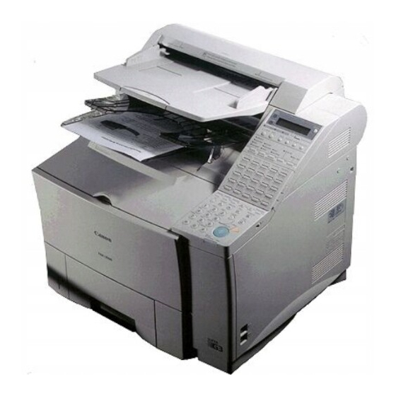
Canon FAX L1000 Service Manual (610 pages)
Canon Fax Machine User Manual
Brand:
Canon
| Category:
Fax Machine
| Size: 6 MB
Table of Contents
Table of Contents
6
Revision History
5
Duplex Unit du
10
Envelope Feeder Ef
10
Paper Feed Unit Pf
10
Illustration Index
12
Chapter 3: Technical Reference
13
Chapter 1 : Safety and Precautions
21
Danger to Personnel
21
Electric Shock
21
AC Line (AC 230V Household Current)
22
Printer High Voltage Terminal
22
Telephone Line
22
High Temperature Parts
23
Fire
24
Moving and Rotating Parts
26
Laser Beams
28
Danger to Equipment
30
Handling the FAX
30
General Precautions
30
Storage and Handling of FX6 Toner Cartridge
32
Before Unsealing the Box
32
Storing Unsealed Parts
33
Storage Environment
33
Effective Life
33
Handling
33
Precautions When Servicing
35
Damage Due to Electrostatic Discharge
35
Lubrication Points
36
Scanner Section
36
Printer Section
37
Paper Load Section
38
Control Boards
39
Replacing ROM
40
Precautions for Data Protection
41
Battery-Backed up Data
41
Backed up by Rechargeable Battery
42
Data Backed up by Rechargeable Battery
42
Reception Image Data Transfer
43
Backed up by Lithium Battery
44
Data Backed up by the Lithium Battery
44
Printing the Lithium Battery Backup Data List
46
Data Clear/Initialization Using Service Operation
48
Master Password
49
What to Do When a Problem Occurs (All Clear)
50
Please Wait
50
Protective Functions
51
Reception Image Data Transfer Function
51
Data Battery Backup Function
51
Built-In Safety Measures
52
Overcurrent Protection
52
Lightning Protection
52
Power Leakage Protection
53
Qualification Required for Installation Work
54
Main Unit Overview
57
Names of Parts and Their Functions
57
Chapter 2 : Operating Instructions
60
Operation Panel
60
Service Operation Functions
67
Service Report Output Functions
69
User Data Flowchart
82
Service Data Setting
97
Service Data Registration/Setting Method
98
Service Mode
98
Service Data Flowchart
99
Service Menu
99
Test Mode
104
Explanation of Sssw (Service Soft Switch Settings)
105
New Sssws/Parameters Added to this Model
106
Test Functions
122
Test Mode Overview
122
Test Mode Flowchart
123
D-Ram Tests
125
Print Test
126
Modem and Ncu Tests
127
Aging Test
131
Faculty Tests
132
Isdn Test
139
Facsimile Overview
145
Specifications
145
Option Overview
146
External View
147
Communications Specifications
150
Scanner Section Specifications
152
Scanning Range
154
Printer Section Specifications
155
Printing Range
157
Theory of Operations
162
Document and Recording Paper Flow
165
Mechanical Overview
165
Unit Layout Diagrams
165
Drive System Layout
167
Electrical System Layout
169
Document Feed Section
174
Scanner Section
174
Optical Section
179
Paper Feeder
187
Printer Section
188
Paper Feed/Eject Section
189
Laser/Scanner Section
192
Toner Cartridge
194
Transfer/Separation Section
200
Fixing Section
201
Ecnt Board Function Block Diagra
208
Scnt Board Component Block Diagram
211
Ecnt Board Component Block Diagram
215
Contact Sensor
218
NCU Board
220
High-Speed Transmission
221
V.8/V.34 Protocol
221
New Function
221
Single Progression Sequential Bi-Level Image Compression Method
236
Encoding Method
237
Construction of Image Data with JBIG Image Compression Encoding
244
Explanation of Bi-Level Image Header Section (Bih)
245
Explanation and Parameters for each Symbol Used in Bih
246
Explanation and Parameters for each Symbol Used in Bid
247
Explanation of Bi-Level Image Data (Bid) Section
247
Energy Save Standby (Ess)
249
Maintenance
253
Periodic Replacement Parts
257
Chapter 4 : Maintenance and Service
257
Periodic Inspections
257
Special Tools
258
Consumables Replacement
259
Recording Paper
259
Toner Cartridge
259
Stamp Ink
260
Document Eject Roller
263
Document Feed Roller
263
Document Pick-Up Roller
263
Main Unit
263
Scanning Glass (Contact Sensor)
263
Separation Roller (Lower)
263
White Sheet
263
Transfer Guide
265
Transfer Charging Roller
268
Cassette Pick-Up Roller/Feed Roller/Separation Roller
270
Multi-Purpose Tray Pick-Up Roller/Separation Pad
272
Feed Roller
274
Pre-Transfer Roller and Registration Arm
279
Paper Feed Belt and Paper Feed Guide
281
Fixing Unit Entrance Guide
283
Fixing Film
284
Delivery Guide
286
Face-Up Deflector, Fixing Delivery Roller and Lower Paper
286
Adjustment Items
287
Parts Replacement
287
Points to Grease
287
Leading Edge Margin Adjustment
288
Precautions for Troubleshooting
290
Error Codes
297
Errors Not Shown on the Display
316
Printer Error Messages
331
Wiring Diagram
332
Signal Description
335
1. Installation
359
Installation
359
Chapter 5 FAX-L1000 Chapter 5: Appendix
360
Where to Set up the Fax
360
Space Around the Fax
362
Power Requirements
363
Setting up the Fax
360
Unpacking: Have You Got Everything
364
Removing the Shipping Material
368
Removing the Packing Materials Inside the Fax Unit
368
Removing the Shipping Tapes
368
Removing the Packing Materials from Paper Cassette 1
370
Removing the Protective Plastic Sheet
371
Assembling the Fax
372
Installing the Toner Cartridge
372
Attaching the Document Feeder Tray
376
Installing Paper Feed Unit (PF-52)
377
Loading Paper in Paper Cassettes 1 and 2
381
Connecting an Extension Phone
388
Loading the Mp Tray
389
Using the MP Tray
389
Turning on and off Use Mp Tray and Setting the Paper Size in the Use Mp Tray Menu
394
Turning on the Power
396
Energy Saver
397
Processing When Trouble Occurs
398
Checking Operations
399
Communication Test
399
Copy Operation
399
Memory in Use
399
Moving the Fax Unit
400
Service Tools
401
Set Operation Mode
402
Operation
403
Scnt Board
412
STAMP Unit
423
Technical Information
561
Maintenance and Service
563
Installation
568
Advertisement
Canon FAX L1000 Portable Manual (96 pages)
Brand:
Canon
| Category:
Fax Machine
| Size: 3 MB
Table of Contents
Symbol Description
4
Symbols Used
4
Table of Contents
7
Chapter 1 Maintenance and Inspection
13
Periodically Replaced Parts
13
Durables and Consumables
13
1Durables
13
Scheduled Servicing Basic Procedure
13
1Periodeical Service Items
13
Chapter 2 Standards and Adjustments
15
Image Adjustments
15
1Image Parallelism Adjustment
15
Scanning System
16
1Action after Replacing the Contact Image Sensor
16
Electrical Adjustment
16
1Procedure after Replacing the Image Processor PCB
16
2Actions to Take before All Clearing (Backing up the User Data)
16
Adf
18
Outline
18
Preparing a Test Sheet for Adjustment
18
Adjusting the Mechanical System
18
Adjusting the Magnification
18
Adjusting the Horizontal Registration
18
Leading Edge Registration Adjustment
19
Chapter 3 Error Code
21
Jam Code
21
1Jam Codes (Main Body)
21
2Jam Codes (ADF)
21
Chapter 4 User Mode Items
23
User Mode Items
23
1Paper Settings
23
2Volume Control
23
3Common Settings
23
4Copy Settings
23
5Tx/Rx Settings
24
6Address Book Set
25
7PRINTER SETTINGS (if an Network Printer Kit Is Attached.)
26
8Timer Settings
27
9Adjust./Cleaning
27
10Report Settings
27
11System Settings
28
Chapter 5 Service Mode
33
Service Soft Switch Settings (SSSW)
33
Outline
33
Bit Switch Composition
33
Sssw-Sw01
33
List of Functions
33
Detailed Discussions of Bit 0
33
Sssw-Sw03
33
Detailed Discussions of Bit 7
34
Sssw-Sw04
34
List of Functions
34
Detailed Discussions of Bit 2
34
Detailed Discussions of Bit 3
34
Detailed Discussions of Bit 4
34
Detailed Discussions of Bit 5
35
Detailed Discussions of Bit 6
35
Detailed Discussions of Bit 7
35
Sssw-Sw05
35
List of Functions
35
Detailed Discussions of Bit 1
35
Detailed Discussions of Bit 2
35
Sssw-Sw12
35
Sssw-Sw13
36
List of Functions
36
Detailed Discussions of Bit 2
37
Sssw-Sw14
37
List of Functions
37
Detailed Discussions of Bit 4
37
Sssw-Sw25
37
Detailed Discussions of Bit 0
37
Detailed Discussions of Bit 2
38
Sssw-Sw28
38
List of Functions
38
Detailed Discussions of Bit 0
38
Detailed Discussions of Bit 1
38
Detailed Discussions of Bit 3
38
Detailed Discussions of Bit 4
38
Detailed Discussions of Bit 5
38
Sssw-Sw30
38
Detailed Discussions of Bit 5
39
Sssw-Sw33
39
List of Functions
39
Detailed Discussions of Bit 0
39
Detailed Discussions of Bit 1
39
Detailed Discussions of Bit 2
39
Menu Switch Settings (MENU)
39
1Menu Switch Composition
39
2<No.005 NL Equalizer
40
3<No.006 Telephone Line Monitor
40
4<No.007 ATT Transmission Level
40
5<No.008 V.34 Modulation Speed Upper Limit
40
6<No.009 V.34 Data Speed Upper Limit
40
7<No.010 Frequency of the Pseudo CI Signal
40
Numeric Parameter Settings (NUMERIC Param.)
40
1Numerical Parameter Composition
40
Transmission Condition (3)
41
3<005: NCC Pause Length (Pre-ID Code)
41
4<006: NCC Pause Length (Post-ID Code)
41
5<010: Line Connection Identification Length
41
6<011: T.30 T1 Timer (for Reception)
42
7<013: T.30 EOL Timer
42
8<015: Hooking Detection Time
42
9<016: Time Length to First Response at Time of Fax/Tel Switchover
42
10<017: Pseudo RBT Signal Pattern on Time Length><018: Pseudo RBT Signal Pattern off Time Length (Short)><019: Pseudo RBT Signal Pattern off Time Length (Long)
42
11<020: Pseudo CI Signal Pattern on Time Length><021: Pseudo CI Signal Pattern off Time Length (Short)><022: Pseudo CI Signal Pattern off Time Length (Long)
42
12<023: CNG Detention Level for Fax/Tel Switchover
42
13<024: Pseudo RBT Transmission Level at Time of Fax/Tel Switchover
42
14<025: Answering Machine Connection Function Signal Detection Time
42
15<027: V.21 Low-Speed Flag Preamble Identification Length
42
Scanner Function Settings (SCANNER)
46
1Numeric Parameter Functional Configuration
46
2<026:Distance from the Standby Position of CIS to the Shading Start Point
46
3<041: Vertical Scan Start Position Adjustment (When Scanning on a Document Fed from ADF)
46
4<042: Horizontal Scan Start Position Adjustment (When Scanning on a Document Fed from ADF)>34
46
5<044: Horizontal Scan End Position Correction (Superfine:scanning on ADF)
47
6<045: Horizontal Scan End Position Correction (Fine:scanning on ADF)
47
7<046: Horizontal Scan End Position Correction (Standard:scanning on ADF)
47
8<047: Vertical Scan Magnification Correction (When Scanning on a Document Fed from ADF)
47
10<054: Pickup Motor Speed Correction (When the ADF Is Used)
47
11<100: Adjustment of the Registration Loop Volume (ADF)
47
12<193: ADF Special Standard-Sized Paper: LGL Misidentification-Ready
47
13<194: ADF Special Standard-Sized Paper: LTR Misidentification-Ready
47
14<195: ADF Special Standard-Sized Paper: LTR_R Misidentification-Ready
47
15<213: XYZ Correction Value (X) of Standard White Plate> (if Equipped with SEND Functions)
48
16<214: XYZ Correction Value (Y) of Standard White Plate> (if Equipped with SEND Functions)
48
17<215: XYZ Correction Value (Z) of Standard White Plate> (if Equipped with SEND Functions)
48
Printer Function Settings (PRINTER)
48
Service Soft Switch Settings (SSSW)
48
Sssw-Sw05
48
Sssw-Sw14
49
Sssw-Sw15
50
Numeric Parameter Settings (NUMERIC Param.)
50
Numeric Parameter Functional Configuration
50
031: Top Registration Adjustment (Manual Feed Tray)
51
032: Top Registration Adjustment (Cassette)
51
033: Top Registration Adjustment (Duplex Unit)
51
034: Left-End Registration Adjustment (Manual Feed Tray)
51
035: Left-End Registration Adjustment (Cassette 1)
51
036: Left-End Registration Adjustment (Cassette 2)
51
039: Left-End Registration Adjustment (Duplex Unit)
51
040: Target Fixing Temperature Adjustment (Manual Feed Tray)
51
041: Target Fixing Temperature Adjustment (Cassette 1)
51
042: Target Fixing Temperature Adjustment (Cassette 2)
51
055: Margin Adjustment at the Right Edge of the Copy
52
056: Margin Adjustment at the Left Edge of the Copy
52
Setting of System Functions (SYSTEM)
53
1Bit Switch Settings
53
Counter Indication (COUNTER)
53
1Counters
53
2Clearing Counters
54
Report Output (REPORT)
55
1Report Output
55
2System Data List
55
3System Dump List
56
4Counter List
57
5Error Log List
57
6Spec List
59
7Service Label
60
8E-RDS Communication Error Log List
61
9Environmental Log Report
62
Data Initialization Mode (CLEAR)
62
1Clear
62
Test Mode (TEST)
63
Overview
63
Outline
63
Test Mode Menu List
63
DRAM Test
65
D-RAM Test<(1) D-RAM TEST
65
Scan Test
66
Scan Test ((2) SCAN TEST)
66
Print Test
66
Print Test ((3) PRINT TEST)
66
Modem Test
67
MODEM Test ((4) MODEM TEST)
67
Faculty Test
69
Function Test <(6) Function Test
69
Cleaning Mode
72
Roller Cleaning Mode ((0) ROLLER CLEAN)
72
Chapter 6 Outline of Components
73
Sensor
73
1List of Sensors
73
Pcbs
74
1List of Pcbs
74
Chapter 7 System Construction
77
Construction
77
1Functional Construction
77
2Functional Block Diagram
78
3Image Processor PCB
79
4DC Controller PCB
79
5Reader Controller PCB
80
6Power Supply PCB
80
7Ncu Pcb
80
8Modular Jack PCB
80
9Modem PCB
80
System Construction
82
1System Configuration
82
2System Configuration
84
Product Specifications
86
2Product Specifications
87
3ADF Specifications
89
5Fax Specifications
89
Function List
90
1Printing Speed
90
2Types of Paper
90
Chapter 8 Upgrading
93
Upgrading
93
1Overview of Upgrade
93
Canon FAX L1000 Simplified Manual (18 pages)
Brand:
Canon
| Category:
Fax Machine
| Size: 0 MB
Advertisement
Advertisement
Related Products
Canon FAX L160
Canon FAX L140
Canon FAX-L100
Canon FAX-L120
Canon FAX-L170
Canon FAX-L150
Canon FAX-L900
Canon FAX-L380S Series
Canon FAX-L380
CANON FAX-L360
Canon Categories
Printer
Digital Camera
All in One Printer
Camcorder
Scanner
More Canon Manuals
Login
Sign In
OR
Sign in with Facebook
Sign in with Google
Upload manual
Upload from disk
Upload from URL