
Related Manuals for Arista 720D Series


Summary of Contents for Arista 720D Series
- Page 1 QUICK START GUIDE 720D Series Ethernet Switch Cognitive Campus Switches CCS-720DP-48S CCS-720DT-48S CCS-720DP-24S CCS-720DT-24S CCS-720DF-48Y CCS-720DF-48Y-DC CCS-720DP-24ZS CCS-720DP-48ZS Arista Networks DOC-05297-07 Arista.com...
- Page 2 The trademarks, logos, and service marks ("Marks") displayed in this documentation are the property of Arista Networks in the United States and other countries. Use of the Marks is subject to the Arista Networks Terms of Use Policy, available at www.arista.com/en/terms-of-use. Use of marks belonging to other parties is for...
-
Page 3: Table Of Contents
Contents Contents Chapter 1: Overview..................1 1.1 Scope..............................1 1.2 Receiving and Inspecting the Equipment..................1 1.3 Installation Process..........................2 1.4 Safety Information..........................2 1.5 Obtaining Technical Assistance......................2 1.6 Product and Documentation Updates....................3 1.7 Specifications............................. 3 Chapter 2: Preparation..................9 2.1 Site Selection.............................9 2.2 Tools and Parts Required for Installation..................10 2.3 Electrostatic Discharge (ESD) Precautions..................10 Chapter 3: Rack Mounting the Switch............ - Page 4 8.8 CCS-720DF-48Y..........................31 8.9 CCS-720DF-48Y-M-S........................32 8.10 CCS-720DP-24ZS..........................32 8.11 CCS-720DP-48ZS..........................33 Chapter 9: Rear Panel...................34 9.1 CCS-720DP-48S-2F / CCS-720DP-48S-M-S-2F................34 9.2 CCS-720DP-24S-2F / CCS-720DP-24S-M-S-2F................34 9.3 CCS-720DT-48S-2F.........................35 9.4 CCS-720DT-24S-2F / CCS-720DT-24S-M-S-2F................35 9.5 CCS-720DT-24S-2R........................35 9.6 CCS-720DT-48S-2R........................36 9.7 CCS-720DF-48Y-2F / CCS-720DF-48Y-M-S-2F................36 9.8 CCS-720DF-48Y-DC-2F........................
-
Page 5: Chapter 1: Overview
Chapter 1 Overview This guide is intended for network or security professionals and technicians who need to install the required Arista 720D Series Ethernet Switch. The following topics are covered in this section: • Scope • Receiving and Inspecting the Equipment •... -
Page 6: Installation Process
Refer to the Arista Networks document Safety Information and Translated Safety Warnings available at https://www.arista.com/en/support/product-documentation Obtaining Technical Assistance Any customer, partner, reseller, or distributor holding a valid Arista Service Contract can obtain technical support in any of the following ways: •... -
Page 7: Product And Documentation Updates
• Phone: +1 866-476-0000 or +1 408-547-5502. Product and Documentation Updates To receive important news on product updates, please visit our website at https://www.arista.com/en/support/ product-documentation. Specifications This section lists the specifications of the Arista Ethernet Switches described in this guide. - Page 8 Table 1: Ethernet Switch Specifications (Dimensions and Weights) Device Size (W x H x D) Weight 440 x 43.5 x 430 mm 6.73 kg CCS-720DP-48S-2F (17.32 x 1.71 x 16.92 inches) (14.83 lbs) 440 x 43.5 x 330 mm 5.81 kg CCS-720DP-24S-2F (17.32 x 1.71 x 12.99 inches) (12.80 lbs)
- Page 9 Overview Table 2: Ethernet Switch Specifications (Operational and Storage) Operating Storage Device Operating Altitude Relative Humidity Temperature Temperature CCS-720DP-48S 0 to 40°C -25 to 70°C 0 to 3,000 meters 5 to 90% (32° to 104°F) (-13 to 158F) (0 to 10,000 feet) (non-condensing) CCS-720DT-48S 0 to 40°C...
- Page 10 Table 3: Ethernet Switch Specifications (Power Ratings) Device Input Power Rating CCS-720DP-48S-2F 100 - 240V~, 10 - 5A, 50/60 Hz CCS-720DP-48S-M-S-2F 100 - 240V~, 10 - 5A, 50/60 Hz CCS-720DP-24S-2F 100 - 240V~, 6 - 3A, 50/60 Hz CCS-720DP-24S-M-S-2F 100 - 240V~, 6 - 3A, 50/60 Hz CCS-720DT-48S-2F 100 - 240V~, 1.2-0.6A, 50/60 Hz CCS-720DT-48S-2R...
- Page 11 Overview Table 4: Ethernet Switch Specifications (PoE Power Budget) Device PoE Power Budget CCS-720DP-48S 745W CCS-720DT-48S CCS-720DP-24S 380W CCS-720DT-24S CCS-720DF-48Y CCS-720DF-48Y-DC CCS-720DP-24ZS 730W CCS-720DP-48ZS 120V: 2x700W 240V: 2x1440W CCS-720DP-48ZS 120V: 700W 240V: 1500W...
- Page 12 Table 5: Ethernet Switch Specifications (System Configurations) Device Downlink Ports Uplink Ports Airflow Power Ports Supply CCS-720DP-48S-2F 48x1G RJ45 4x10G SFP+ Front to rear CCS-720DP-48S-M-S-2F 48x1G RJ45 4x10G SFP+ Front to rear CCS-720DP-24S-2F 24x1G RJ45 4x10G SFP+ Front to rear CCS-720DP-24S-M-S-2F 24x1G RJ45 4x10G SFP+...
-
Page 13: Chapter 2: Preparation
Chapter 2 Preparation This section describes the initial set up and preparation for installing the switch. The following topics are covered in this section: • Site Selection • Tools and Parts Required for Installation • Electrostatic Discharge (ESD) Precautions Site Selection The following criteria should be considered when selecting a site to install the switch: •... -
Page 14: Tools And Parts Required For Installation
Tools and Parts Required for Installation Each device has an accessory kit containing the parts required to install the switch. In addition to the accessory kit, the following tools and equipment are required to install the switch: Two-Post Rack • #1 and #3 Phillips head screwdrivers (this may differ based on supplied accessories) •... -
Page 15: Chapter 3: Rack Mounting The Switch
Chapter 3 Rack Mounting the Switch This section provides instructions on how to to rack mount the switch. The following topics are covered in this section: • Two-Post Rack Mount Two-Post Rack Mount This section provides instructions for mounting the switch in a two-post rack. To mount the switch onto a two-post rack, assemble the mounting brackets to the chassis, then attach the brackets to the rack posts. -
Page 16: Inserting The Switch Into The Rack
1 Flat head screw M4x6mm 2 Extended L-bracket (MTL-05776) Note: For more information regarding the screw size, refer to Screw Size Details 1. Position the L-bracket or Extended L-bracket (flush, 1.5" offset, or 2.5" offset) by aligning with the chassis holes on both sides of the switch and fixing it with M4x6mm flat head screws. - Page 17 Rack Mounting the Switch 1 Screw M4x25mm (not included in the kit) 2 Two-post rack Note: For more information regarding the screw size, refer to Screw Size Details 1. Lift the chassis, attached with L-brackets, into the rack. 2. Place the switch into the rack by aligning it with the mounting bracket. 3.
-
Page 18: Chapter 4: Cabling The Switch
Chapter 4 Cabling the Switch The Cabling the Switch section includes the following topics: • Grounding the Switch • Connecting Power Cables • Connecting Serial and Management Cables Grounding the Switch This section describes the importance of grounding the device to the data center ground. Normally, the functional grounding of the switch is achieved through the input connection. -
Page 19: Grounding Lug Preparation
Cabling the Switch 4.1.1 Grounding Lug Preparation The following procedure connects the chassis to the data center ground: 1. Prepare the (stranded) copper wiring for the ground wire. 2. Use agency-approved compression (pressure) lugs for wiring terminations. 3. Slip on heat-shrink tubing on the wire end before assembling the lugs on to the wire. 4. -
Page 20: Connecting Ac Power
Cet appareil requiert une protection contre les surintensités. 4.2.1 Connecting AC Power This section describes how to connect the AC power supply to the device. The AC power supplies are internal to each switch. Power requirements vary by switch. Refer to the Specifications section for information regarding your specific device. -
Page 21: Connecting Dc Power Supply To Power Source
Cabling the Switch 4.2.3 Connecting DC Power Supply to Power Source This section describes connecting the DC power supply to the power source. Important: • Wire size must comply with local and national requirements and electrical codes. Use only copper wire. Calibre doit respecter les exigences locales et nationales et les codes de l’électricité. - Page 22 Table 7: RJ-45 to DB-9 Connections RJ-45 DB-9 RJ-45 DB-9 Figure 4-3: Front Panel Ports 1 Ethernet Management Port 2 USB Port 3 Console Serial Port Connect the front panel ports as described below: • Console (Serial) Port: Connect to a computer with the RJ-45 to DB-9 serial adapter cable. The switch uses the following default settings: •...
-
Page 23: Chapter 5: Configuring The Switch
Chapter 5 Configuring the Switch Arista switches ship from the factory in Zero Touch Provisioning (ZTP) mode. ZTP configures the switch without user intervention by downloading a startup configuration file or a boot script from a location specified by a DHCP server. To manually configure a switch, ZTP is bypassed. The initial configuration provides one username (admin) that is accessible only through the console port because it has no password. - Page 24 11. When the management port IP address is configured, use this command to access the switch from a host, using the address configured in step 9: ssh admin@192.0.2.8 Refer to the Arista Networks User Manual for complete switch configuration information.
-
Page 25: Chapter 6: Status Indicators
Chapter 6 Status Indicators This section describes the front panel LED status of the device. LED Status Indicators... - Page 27 Status Indicators Table 8: LED Status LED Name LED State Device Status System Status LED No power or in the midst of a power cycle. Blinking Green The system is powering up. Green The system is operating in a normal initialization sequence.
- Page 28 Table 9: Port LED Modes Port LEDs Normal Mode PoE Mode Speed Mode 1GE RJ45 Port link is down No PoE Blinking Amber 10M Port LED Green Port link is up Blinking Amber 100M Amber Amber Port is software Amber Green disabled 2.5GE RJ45...
-
Page 29: Chapter 7: Parts List
Chapter 7 Parts List This section lists the installation parts contained in the switch accessory kit. Each device has an accessory kit that contains the necessary parts to install the switch. Two-post Rack Mount The following accessories are available along with the device: •... - Page 30 Spare SKU Description KIT-720 Spare Accessory kit for Arista 720D Series 1RU Switches KIT-7010-4Post Spare 4-post rack mount kit for 7010 switches SKU and Product Details The following are the list of SKU numbers related to the respective product.
- Page 31 Parts List Table 10: SKU and Product Details Product Description CCS-720DP-48S-2F Arista 720DP, 48x1G PoE, 4x10G SFP+ switch, front to rear air, 2x950W AC CCS-720DP-48S-M-S-2F Arista 720DP, 48x1G POE, 4x10G SFP+ switch, expanded memory, front to rear air, 2x950W AC...
-
Page 32: Chapter 8: Front Panel
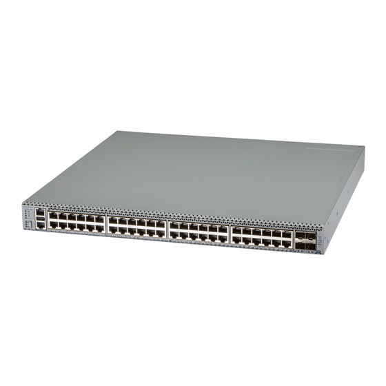
Chapter 8 Front Panel This section describes the front panel of the Ethernet Switch. CCS-720DP-48S The CCS-720DP-48S front panel includes the following key components: Figure 8-1: CCS-720DP-48S Front Panel System Status LEDs 4x10G SFP+ Ports RJ45 Ethernet Management Port SFP+ Port LEDs USB Port 48x1G PoE Ports Console Port... -
Page 33: Ccs-720Dp-24S
Front Panel System Status LEDs 4x10G SFP+ Ports RJ45 Ethernet Management Port SFP+ Port LEDs USB Port 48x1G PoE Ports Console Port Mode Button Port LEDs 10 Mode Status LEDs CCS-720DP-24S The CCS-720DP-24S front panel includes the following key components: Figure 8-3: CCS-720DP-24S-M-S Front Panel System Status LEDs 4x10G SFP+ Ports... -
Page 34: Ccs-720Dt-48S
CCS-720DT-48S The CCS-720DT-48S front panel includes the following key components: Figure 8-5: CCS-720DT-48S Front Panel System Status LEDs 4x10G SFP+ Ports RJ45 Ethernet Management Port SFP+ Port LEDs USB Port 48x1G PoE Ports Console Port Mode Button Port LEDs 10 Mode Status LEDs CCS-720DT-24S The CCS-720DT-24S front panel includes the following key components: Figure 8-6: CCS-720DT-24S Front Panel... -
Page 35: Ccs-720Dt-24S-M-S
Front Panel CCS-720DT-24S-M-S The CCS-720DT-24S-M-S front panel includes the following key components: Figure 8-7: CCS-720DT-24S-M-S Front Panel System Status LEDs 4x10G SFP+ Ports RJ45 Ethernet Management Port SFP+ Port LEDs USB Port 24x1G Ports Console Port Mode Button Port LEDs 10 Mode Status LEDs CCS-720DF-48Y The CCS-720DF-48Y front panel includes the following key components:... -
Page 36: Ccs-720Df-48Y-M-S
CCS-720DF-48Y-M-S The CCS-720DF-48Y-M-S front panel includes the following key components: Figure 8-9: CCS-720DF-48Y-M-S Front Panel System Status LEDs 4x25G SFP28 Ports RJ45 Ethernet Management Port SFP28 Port LEDs USB Port 48x1G SFP Ports Console Port Mode Button Port LEDs 10 Mode Status LEDs 8.10 CCS-720DP-24ZS The CCS-720DP-24ZS front panel includes the following key components:... -
Page 37: Ccs-720Dp-48Zs
Front Panel 8.11 CCS-720DP-48ZS The CCS-720DP-48ZS front panel includes the following key components: Figure 8-11: CCS-720DP-48ZS Front Panel System Status LEDs 4x10G SFP+ Ports RJ45 Ethernet Management Port SFP+ Port LEDs USB Port 48x2.5G PoE Ports Console Port Mode Button Port LEDs 10 Mode Status LEDs... -
Page 38: Chapter 9: Rear Panel
Chapter 9 Rear Panel The section describes the rear panel of the Ethernet Switch. CCS-720DP-48S-2F / CCS-720DP-48S-M-S-2F The CCS-720DP-48S-2F / CCS-720DP-48S-M-S-2F rear panel includes the following key components: Figure 9-1: CCS-720DP-48S-2F / CCS-720DP-48S-M-S-2F Rear Panel Power supply 1 (PS1) Fan 3 Functional Grounding Point Fan 4 Fan 1... -
Page 39: Ccs-720Dt-48S-2F
Rear Panel CCS-720DT-48S-2F The CCS-720DT-48S-2F rear panel includes the following key components: Figure 9-3: CCS-720DT-48S-2F Rear Panel Power supply 1 (PS1) Fan 2 Functional Grounding Point Power Supply 2 (PS2) Fan 1 CCS-720DT-24S-2F / CCS-720DT-24S-M-S-2F The CCS-720DT-24S-2F / CCS-720DT-24S-M-S-2F rear panel includes the following key components: Figure 9-4: CCS-720DT-24S-2F / CCS-720DT-24S-M-S-2F Rear Panel Power supply 1 (PS1) Fan 2... -
Page 40: Ccs-720Dt-48S-2R
CCS-720DT-48S-2R The CCS-720DT-48S-2R rear panel includes the following key components: Figure 9-6: CCS-720DT-48S-2R Rear Panel Power supply 1 (PS1) Fan 2 Functional Grounding Point Power Supply 2 (PS2) Fan 1 CCS-720DF-48Y-2F / CCS-720DF-48Y-M-S-2F The CCS-720DF-48Y-2F / CCS-720DF-48Y-M-S-2F rear panel includes the following key components: Figure 9-7: CCS-720DF-48Y-2F / CCS-720DF-48Y-M-S-2F Rear Panel Power supply 1 (PS1) Fan 2... -
Page 41: Ccs-720Dp-24Zs-2F
Rear Panel Power supply 1 (PS1) Fan 2 Functional Grounding Point Fan 3 Fan 1 Power Supply 2 (PS2) CCS-720DP-24ZS-2F The CCS-720DP-24ZS-2F rear panel includes the following key components: Figure 9-9: CCS-720DP-24ZS-2F Rear Panel Power supply 1 (PS1) Fan 3 Functional Grounding Point Fan 4 Fan 1... -
Page 42: Appendix A: Operating Mode Button
Appendix A Operating Mode Button This section describes the functionality of the mode button located on the front panel of the switch. Figure A-1: Mode Button States The mode button port LEDs will transition to different modes as listed below when the user presses the mode button for less than 2 seconds, and the same is indicated by the corresponding mode status LED. -
Page 43: Appendix B: Regulatory Model Numbers
Appendix B Regulatory Model Numbers This section lists the Regulatory Model Numbers (RMNs) of the Ethernet switches described in this guide. Table 11: Regulatory Model Numbers Product Number Regulatory Model Number (RMN) CCS-720DP-48S-2F AN1755 CCS-720DP-48S-M-S-2F CCS-720DP-24S-2F AN1756 CCS-720DP-24S-M-S-2F CCS-720DT-48S-2F AN1784 CCS-720DT-48S-2R AN1784 CCS-720DT-24S-2F... -
Page 44: Appendix C: Screw Size Details
Appendix C Screw Size Details This section describes the detailed screw size information required for mounting the switch. Refer to Rack Mounting the Switch... -
Page 45: Appendix D: Bsmi Class A Statement
Appendix D BSMI Class A Statement This appendix provides Taiwan BSMI Class A Statement information for switches described in this guide. Figure D-1: Taiwan BSMI Class A Statement... -
Page 46: Appendix E: Rohs Information
Appendix E RoHS Information This appendix provides Taiwan and China RoHS information for the Ethernet switches described in this guide. - Page 47 RoHS Information...
- Page 49 RoHS Information...
- Page 51 RoHS Information...
Need help?
Do you have a question about the 720D Series and is the answer not in the manual?
Questions and answers