
Related Manuals for Arista 7500N Series


Summary of Contents for Arista 7500N Series
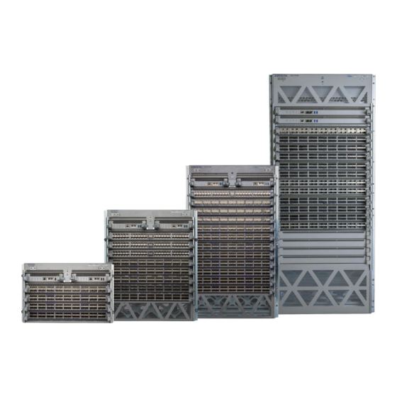
- Page 1 Quick Start Guide 7500N Series Modular Data Center Switch Arista Networks www.arista.com PDOC-00114-14...
- Page 2 © Copyright 2020 Arista Networks, Inc. The information contained herein is subject to change without notice. Arista Networks and the Arista logo are trademarks of Arista Networks, Inc in the United States and other countries. Other product or service names may be trademarks or service marks of others.
-
Page 3: Table Of Contents
Cabling the DC Power Supply ......................27 4.4.1 DC Power Supplies........................27 4.4.2 Wire and Lug Preparation ......................27 4.4.3 PWR-3K-DC-RED Power Supply..................... 28 DC Power Adapter Installation for PWR-2700-DC-R................29 9 March 2020iii Quick Start Guide: 7500N Series Modular Switches... - Page 4 F.2.1 Removing Fabric Module ......................76 F.2.2 Removing Fabric Module Blank ....................76 F.2.3 Installing Fabric Module ......................76 F.2.4 Removing Service Provider 7500N Series Fan and Safety Guard .......... 76 9 March 2020Quick Start Guide: 7500N Series Modular Switches...
- Page 5 F.4.3 Installing Supervisor Module....................78 Linecards .............................. 78 F.5.1 Removing Linecard ........................79 F.5.2 Removing Linecard Blank ......................79 F.5.3 Installing Linecard ........................79 Appendix G Taiwan RoHS Information ................81 9 March 2020v Quick Start Guide: 7500N Series Modular Switches...
- Page 6 9 March 2020Quick Start Guide: 7500N Series Modular Switches...
-
Page 7: Chapter 1 Overview
Inspect the packing list and confirm that you received all listed items. Compare the packing list with your purchase 7500N Series Modular Switches order. Appendix B provides a list of components included with the switch. -
Page 8: Safety Information
Aucune pièce réparable par l'utilisateur à l'intérieur. Confiez toute réparation à un technicien qualifié. Safety Information Refer to the Arista Networks document Safety Information and Translated Safety Warnings available at: https://www.arista.com/en/support/product-documentation Obtaining Technical Assistance Any customer, partner, reseller or distributor holding a valid Arista Service Contract can obtain... -
Page 9: Specifications
Chapter 1: Overview Specifications Specifications Table 1-1 lists the specifications of Arista Data Center modular switches covered by this guide. Table 1-1 Modular switch specifications DCS-7504N DCS-7508N DCS-7512N DCS-7516N Height 7RU: 312 mm (12.25 13RU: 578 mm (22.75 18RU: 801 mm (31.53 29RU: 1289 mm (50.75... - Page 10 7504N Series System Full chassis loaded with 3150 W / 3400 W 2 DCS-7500E-SUP 4 DCS-7504E-FM 4 DCS-7500E-36Q-LC Full chassis loaded with 3500 W / 4500 W 2 DCS-7500-SUP2 4 DCS-7504R-FM 4 DCS-7500E-36CQ-LC Quick Start Guide: 7500N Series Modular Switches...
- Page 11 Chapter 1: Overview Specifications Table 1-2 7500N Series power specifications (Continued) Power Draw (Typical / Module Type Part Number {Hot}Maximum) 7508N Series System Full chassis loaded with 5500 W / 6400 W 2 DCS-7500E-SUP 6 DCS-7508E-FM 8 DCS-7500E-36Q-LC Full chassis loaded with...
- Page 12 Specifications Chapter 1: Overview Table 1-2 7500N Series power specifications (Continued) Power Draw (Typical / Module Type Part Number {Hot}Maximum) 7516N Series System Full chassis loaded with 16000 W / 19000 W / 21000 W 2 DCS-7516-SUP, Note: 7516N systems...
-
Page 13: Chapter 2 Preparation
88.6 cm (34.9 in.) 36.8 cm (14.5 in.) DCS-7512N 60 cm (24 in.) 94.0 cm (37.0 in.) 50.8 cm (20.0 in.) DCS-7516N 60 cm (24 in.) 94.8 cm (37.3 in.) 50.8 cm (20.0 in.) Quick Start Guide: 7500N Series Modular Switches... -
Page 14: Tools And Parts Required For Installation
The accessory kit provides the required mounting brackets or shelf for each switch. Power Requirements: • Arista switches require a minimum number of operating power supplies in the top section of all chassis, AC or DC and for each power domain of switches with multiple power domains. Refer to Power Supply Specifications for more details regarding your switch. -
Page 15: Electrostatic Discharge (Esd) Precautions
Minimize handling of assemblies and components. • Keep replacement parts in their original static-free packaging. • Remove all plastic, foam, vinyl, paper, and other static-generating materials from the work area. • Use tools that do not create ESD. Quick Start Guide: 7500N Series Modular Switches... - Page 16 Electrostatic Discharge (ESD) Precautions Chapter 2: Preparation Quick Start Guide: 7500N Series Modular Switches...
-
Page 17: Chapter 3 Rack Mounting The Switch
12). Position the flanges that attach to the rack posts toward the rear of the chassis. Step 2 Attach both center-mount brackets to the chassis. Each bracket requires ten M4x8 pan-head Phillips screw. Quick Start Guide: 7500N Series Modular Switches... -
Page 18: Inserting The Switch Into The Rack
Step 2 Lift the chassis into the rack. Position the flanges against the rack posts (Figure 3-2). Figure 3-2: Lifting the chassis into the two post rack Step 3 Select mounting screws that fit your equipment rack. Quick Start Guide: 7500N Series Modular Switches... -
Page 19: Four-Post Rack Mount
Attach the front bracket to the post with screws that can be threaded through the rack post. Step 2 Secure the shelf support to the post with nuts that fit the screws threaded through the post. Quick Start Guide: 7500N Series Modular Switches... - Page 20 Attach the parts as displayed in Figure 3-5-left. Threaded rack holes: Attach the shelf support to the post with screws that thread into the rack post. The back bracket is not required on threaded racks. Quick Start Guide: 7500N Series Modular Switches...
- Page 21 Step 8 Install the right shelf on the right front and right rear rack posts by repeating step 5 and step 6 to obtain the rack configuration shown in Figure 3-8. Figure 3-6: Adjusting the left shelf Rear rack post Left shelf Front rack post Quick Start Guide: 7500N Series Modular Switches...
-
Page 22: Inserting The Switch Into The Rack
Step 1 Move the chassis to the rack using a mechanical lift (Figure 3-8). Note If modules are inserted in the chassis, use the lift carefully to avoid damaging any components. Step 2 Lift the chassis into the rack. Figure 3-8: Lifting the chassis Quick Start Guide: 7500N Series Modular Switches... -
Page 23: 7512N And 7516N Shelf Rack Mount Installation
The rack mounting assembly is for the 7512N and 7516N Series switch. 3.2.1 Assembling the Shelf Step 1 For threaded racks, remove the plastic alignment spacers and use the 3 mm diameter alignment pins (Figure 3-10). Figure 3-10: Alignment spacer Quick Start Guide: 7500N Series Modular Switches... - Page 24 7512N and 7516N Shelf Rack Mount Installation Chapter 3: Rack Mounting the Switch Figure 3-11: Rack mount shelf orientation 7512N Top (Front) Cage nut locations 7516N Top (Front) Switch Bottom Rack (Rear - both switches) Quick Start Guide: 7500N Series Modular Switches...
- Page 25 Attach the front bracket to the post with screws that can be threaded through the rack post. Step 3 Hook the alignment pin to the bottom hole of the 6th U from bottom (Figure 3-12 on page 20). Quick Start Guide: 7500N Series Modular Switches...
- Page 26 Unthreaded rack holes: Use the M6 screws and cage nuts supplied in the accessory kit. Threaded rack holes: Attach the shelf support to the post with screws that thread into the rack post. Quick Start Guide: 7500N Series Modular Switches...
- Page 27 (Figure 3-14 on page 22). Step 7 Rear: Fasten screws to all holes • Front: Fasten screws only where indicated with arrows (2x). • Rear: Fasten screws to all holes. Quick Start Guide: 7500N Series Modular Switches...
-
Page 28: Inserting The Switch Into The Rack
3.2.2 Inserting the Switch into the Rack The rack mounting assembly is identical for all 7500N Series switches. Illustrations in this chapter depict the mounting of an unpopulated 12- or 16-slot chassis. Step 1 Move the chassis to the rack using a mechanical lift... - Page 29 Chapter 3: Rack Mounting the Switch 7512N and 7516N Shelf Rack Mount Installation Figure 3-15: Lifting the 12-slot chassis Step 2 Carefully install the switch into the rack. Figure 3-16: Installing the switch into the rack Quick Start Guide: 7500N Series Modular Switches...
- Page 30 Step 4 Secure the chassis by use of 10 rack screws attaching the ears of the chassis to the front flanges of the rack posts (Figure 3-17). Step 5 After completing the Shelf Rack Mount Installation, proceed to Chapter Quick Start Guide: 7500N Series Modular Switches...
-
Page 31: Chapter 4 Cabling The Modular Switch
Chapter 4 Cabling the Modular Switch Cabling the Power Supplies Before you begin, refer to the Arista Networks document Compliance and Safety Guide available at: https://www.arista.com/en/support/product-documentation. Important! Power down the switch: Remove all power cords from the power inlets. Mettez le commutateur: Retirez tous les cordons d'alimentation des prises d'alimentation. -
Page 32: Cabling Secondary Ground
Important! This equipment must be grounded. Never defeat the ground conductor. This unit requires over-current protection. Cet équipement doit être mis à la terre. Ne jamais modifier le conducteur de terre. Cet appareil nécessite de protection contre les surintensités. Quick Start Guide: 7500N Series Modular Switches... -
Page 33: Cabling The Ac Power Supply
Le - 48V et câbles de batterie-retour sont une paire courir à côté de l'autre et doivent être à peu près la même longueur. 4.4.1 DC Power Supplies The 7500N Series chassis supports two DC power supplies. • PWR-3K-DC-RED Power Supply •... -
Page 34: Pwr-3K-Dc-Red Power Supply
• The tubing should extend over the lug’s barrel and the wire's insulator. Step 4 Shrink the tubing with a heat gun. 4.4.3 PWR-3K-DC-RED Power Supply Figure 4-4 displays the PWR-3K-DC-RED power supply. Quick Start Guide: 7500N Series Modular Switches... -
Page 35: Dc Power Adapter Installation For Pwr-2700-Dc-R
Connecting the Ground to PWR-2700-DC-R Power Supply The primary ground on the system requires a 2 – 4 AWG 5/16 inch lug per power supply. Figure 4-5 displays the PWR-2700-DC-R power supply without the DC adapter. Quick Start Guide: 7500N Series Modular Switches... -
Page 36: Connecting The Power Cable Lug To The Terminal Studs
Section 4.4.2. Step 2 Remove the clear plastic cover protecting the terminal studs on the adapter by lifting the small center tab while sliding the cover off the adapter. Plastic lid Center tab Quick Start Guide: 7500N Series Modular Switches... - Page 37 Attach the positive (+) DC source power cable lug to the RTN (return) terminal. • Attach the negative (–) DC source power cable lug to the –48V (input) terminal. • Torque the four flange locking nuts to 2.7 N-m (24 in.-lbs.). Compression lugs -48V Compression lugs Quick Start Guide: 7500N Series Modular Switches...
- Page 38 Step 8 Attach the power cable to the DC power source. Important! Apply the ground connection first during installation and remove last when removing power. Appliquer le motif connexion tout d'abord pendant l'installation et supprimer dernière lors du retrait de puissance. Quick Start Guide: 7500N Series Modular Switches...
-
Page 39: Power Supply Specifications
Table 4-2, in the top section behind the supervisors. • For 8- & 12-slot chassis, (grouped power supplies top and bottom) Arista recommends equal number of power supplies in the top and bottom groups. • For the 16-slot chassis with 2 power domains, the power domain with the lowest number of power supplies prescribes the total power available, therefore, Arista recommends equal number of PSUs in each domain. -
Page 40: Power Supply Redundancy
The following appendices display the location of the following component on all switches described in this guide. Appendix C displays the front panel location of the supervisor modules. Appendix D displays the rear panel location of power supplies and fabric modules. Quick Start Guide: 7500N Series Modular Switches... -
Page 41: Connecting Supervisor Cables
Figure 4-6: Supervisor DCS-7500E-SUP Status LED Fan module status LED Active LED USB ports Fabric module status LED Ethernet management Linecard status LED ports Serial console port Power supply status LED Quick Start Guide: 7500N Series Modular Switches... - Page 42 • No parity bits • 8 data bits The DCS-7516-SUP supervisor cards must be installed in one of the two slots designated for them in the DCS-7516N switch as shown in Figure 4-9. Quick Start Guide: 7500N Series Modular Switches...
- Page 43 • Connect to 10/100/1000 management network with RJ-45 cable. USB Port: • May be used for software or configuration updates. Clock Input Port: Port type is MCX connector, 2-5.5V, 50 ohm termination. • Quick Start Guide: 7500N Series Modular Switches...
-
Page 44: Connecting Line Card Modules And Cables
Flexion excessive peut endommager les câbles d'interface, en particulier les câbles optiques. Note You must ensure that any open slots for modules, power supplies, etc. are covered by the appropriate “blank” plates. Check with your local Arista Networks representative if you have questions. Quick Start Guide: 7500N Series Modular Switches... -
Page 45: Chapter 5 Configuring The Modular Switch
Chapter 5 Configuring the Modular Switch Arista switches ship from the factory in Zero Touch Provisioning (ZTP) mode. ZTP configures the switch without user intervention by downloading a startup configuration file or a boot script from a location specified by a DHCP server. To manually configure a switch, ZTP is bypassed. The initial configuration... - Page 46 Step 11 When the management port IP address is configured, use this command to access the switch from a host, using the address configured in step 9: ssh admin@192.0.2.8 Arista Networks User Manual Refer to the for complete switch configuration information. Quick Start Guide: 7500N Series Modular Switches...
-
Page 47: Appendix A Status Indicators
Figure A-1: Supervisor 7500E-SUP Status LED Fan module status LED Active LED USB ports Fabric module status LED Ethernet management Linecard status LED ports Serial console port Power supply status LED Quick Start Guide: 7500N Series Modular Switches... - Page 48 Table A-1 interprets the states of these two LEDs. Table A-1 Supervisor activity LED states LED Name LED State Supervisor State Status No power, failed, or improperly inserted. Green Operating normally. Supervisor failed. Quick Start Guide: 7500N Series Modular Switches...
-
Page 49: Line Card Module Indicators
LEDs on each line card. Figure A-4: Line card Status LED Status LED QSFP port 2 LEDs QSFP port 4 LEDs QSFP port 1 LEDs QSFP port 3 LEDs 10G / 40G /100G QSFP port LEDs Quick Start Guide: 7500N Series Modular Switches... -
Page 50: Fabric Status Indicators
Figure A-5 on page 44 displays fan status and fabric status LEDs on the switch. Note Gen 1 Fabric modules are not supported. Figure A-5: 7504N (left) and 7508N fan status and fabric status LEDs Quick Start Guide: 7500N Series Modular Switches... -
Page 51: Power Supply Status Indicators
The power supply LEDs are on the power supply modules.The position of the LEDs are on the rear of each switch. Figure A-7 on page 46 displays all the power supply modules supported on the 7500N. Quick Start Guide: 7500N Series Modular Switches... - Page 52 Appendix A: Status Indicators Figure A-7: 7500N power supplies Note The LEDs for the power supplies with three-LED status indicators are: DC Good Fault and Vin Good from top to bottom as shown above. Quick Start Guide: 7500N Series Modular Switches...
- Page 53 Green No Input Power DC Good Supply installed in Fault chassis Vin Good Input power DC Good Blinking Amber, 0.5 present Fault sec on/off Supply not seated Vin Good Blinking Green in chassis Quick Start Guide: 7500N Series Modular Switches...
- Page 54 Power Supply Status Indicators Appendix A: Status Indicators Quick Start Guide: 7500N Series Modular Switches...
-
Page 55: Appendix B Parts List
Section B.4 Number of Power cords (C19 - C20 type) included Warning All provided power cables are for use only with Arista products. Câbles d’alimentation doivent être utilisés uniquement avec des produits de Arista Quick Start Guide: 7500N Series Modular Switches... -
Page 56: Parts Used In All Rack Mount Configurations
The following sections list the parts provided for the two-post rack mount installation. Table B-3 Two-Post rack mount parts Quantity Description Center-mount brackets M4x8 pan-head Phillips screws Figure B-1: Two-Post rack mount parts Center-mount brackets (DCS-7508N only) Center-mount brackets (DCS-7504N only) M4x8 pan-head Phillips screws Quick Start Guide: 7500N Series Modular Switches... -
Page 57: Four-Post Rack Mount Parts For 4-Slot And 8-Slot Chassis
11 (17) #12-24 pan-head Phillips screws. #10-32 Hex Nuts. 11 (17) #10-32 pan-head Phillips screws. Adjustable Wrench 1. Quantities in parentheses “()” are for the 7508N where the quantities differ from the 7504N. Quick Start Guide: 7500N Series Modular Switches... - Page 58 Front brackets (DCS-7504N Left shelf M6 hex nuts only) Front brackets (DCS-7508N Right shelf M6x16 pan-head Phillips only) screws Shelf support M6 cage nuts Back brackets (not needed for racks with threaded holes) Quick Start Guide: 7500N Series Modular Switches...
-
Page 59: Four Post Rack Mount For 12-Slot And 16-Slot Chassis
Table B-5 Four-Post rack mount parts for the 12- and 16-slot chassis Quantity Description Shelf (or cradle) Left shelf support Right shelf support M6 cage nuts square hole M6X16 pan-head Phillips screws M5X16mm pan-head Phillip screws 12-24X5/8 pan-head Phillip screws 10-32X5/8 pan-head Phillip screws Quick Start Guide: 7500N Series Modular Switches... - Page 60 12- and 16-slot chassis Cradle #10-32X5/8 pan-head Phillip M6 cage nuts (for square hole screws racks) Left telescoping arm #12-24X5/8 pan-head Phillip M6x16 pan-head Phillips screws screws Right telescoping arm M5X16mm pan-head Phillip screws Quick Start Guide: 7500N Series Modular Switches...
-
Page 61: Appendix C Front Panel
All devices are designed to fit in a 19” rack. Illustrations are not to scale. Figure C-1: DCS-7504N front panel (fully populated) Linecard ejector button Supervisor ejector button Ground Linecard ejector handle Supervisor ejector handle Quick Start Guide: 7500N Series Modular Switches... - Page 62 Appendix C: Front Panel Figure C-2: DCS-7508N front panel (fully populated) Linecard ejector button Supervisor ejector button Ground Linecard ejector handle Supervisor ejector handle Quick Start Guide: 7500N Series Modular Switches...
- Page 63 Appendix C: Front Panel Figure C-3: DCS-7512N front panel (fully populated) Linecard ejector button Supervisor ejector button Ground Linecard ejector handle Supervisor ejector handle Quick Start Guide: 7500N Series Modular Switches...
- Page 64 Appendix C: Front Panel Figure C-4: DCS-7516N front panel (fully populated) Linecard ejector button Supervisor ejector button Ground Linecard ejector handle Supervisor ejector handle Quick Start Guide: 7500N Series Modular Switches...
-
Page 65: Appendix D Rear Panel
This appendix displays the rear panel of all switches covered by this guide. Figure D-1: DCS-7504N rear panel (fully populated) Fabric module screw Chassis ground Ground Fabric module ejector handle Ejector button Fabric module status LEDs Release lever Status LEDs Quick Start Guide: 7500N Series Modular Switches... - Page 66 Power cord clip (optional) Fabric module ejector handles 12 Status LEDs (PS1) Status LEDs (PS5) Chassis ground (secondary) Ejector button Ejector button Fabric module status LEDs Release lever Release lever PSU top row (PS1) Quick Start Guide: 7500N Series Modular Switches...
- Page 67 Power cord clip (optional) Fabric module ejector handles 12 Status LEDs (PS1) Status LEDs (PS7) Chassis ground (secondary) Ejector button Ejector button Fabric module status LEDs Release lever Release lever PSU top row (PS1) Quick Start Guide: 7500N Series Modular Switches...
- Page 68 Appendix D: Rear Panel Figure D-4: DCS-7516N rear panel (fully populated) Power domain 2 (PSU11-PSU20) Fabric module Fabric module ejector handles Fabric module status LEDs Chassis ground (secondary) Power domain 1 (PSU1-PSU10) Quick Start Guide: 7500N Series Modular Switches...
-
Page 69: Appendix E Line Cards
2 MPO ports for up to 72 10Gb Ethernet ports. The two 100G MTP/MPO ports provide 100G capability using Arista Multi-speed Ports (MXP) with integrated optics. MXP ports use 100GBASE-SR10 (Short Range) transceivers and are fully compatible with any standards compliant 100GBASE-SR10 ports. - Page 70 The 48 port 1/10GbE SFP+ line card has 48 SFP+ ports. Having 48 ports of SFP+ ports allows this line card the flexibility to utilize any existing Arista SFP+ optic or direct attach cables, and to support both 1Gb and 10Gb speeds.
- Page 71 100GbE the card allows each port to operate in a choice of 4 x 10GbE (using 40GbE optics), 40GbE, or 100GbE. Status LED 40/100G port LEDS DCS-7500E-48T-LC The 48 port RJ45 10GBASE-T wire-speed line card has 48 ports of RJ45 ports that supports 10Gb speeds. Quick Start Guide: 7500N Series Modular Switches...
- Page 72 25G Ethernet or 2 x 50G Ethernet. This flexibility allows for a choice of 5 speeds on all ports and allow for simple migration from 10G to 100G and a wide range of combinations. Status LED Port LEDS Quick Start Guide: 7500N Series Modular Switches...
- Page 73 Each Packet Processor connects to 6 ports of 100G with 4GB of deep packet buffer, the 100G ports support either QSFP100 (100G) or QSFP+ (40G). Status LED 100G MACsec port LEDS Quick Start Guide: 7500N Series Modular Switches...
- Page 74 The 36 port QSFP100 line card allows 36 x 100G of wire rate performance. Status LED Port LEDS DCS-7500R2A-36CQ-LC The 36 port QSFP100 line card allows 36 x 100G of wire rate performance. Status LED 100G ports Quick Start Guide: 7500N Series Modular Switches...
- Page 75 The 36 port QSFP100 line card allows 36 x 100G of wire rate performance. Status LED 100G port LEDs DCS-7500R2AK-36CQ-LC The 36 port QSFP100 line card allows 36 x 100G of wire rate performance. Status LED 100G ports Quick Start Guide: 7500N Series Modular Switches...
- Page 76 The 8 port tunable coherent DWDM with MACsec line card allows 200G of performance for long haul data. Status LED CFP2 port DCS-7500R3-36CQ-LC and DCS-7500R3K-36CQ-LC The line card can support up to 36 100G ports or 72 50G ports. Quick Start Guide: 7500N Series Modular Switches...
- Page 77 The line card can support 24, wire speed 400G OSFP ports or up to 96 100G ports with breakout cables and optics. The line card can support 10G, 25G, and 50G speeds with optics or cables. Status LED 400G ports 400G port LEDs Quick Start Guide: 7500N Series Modular Switches...
- Page 78 Appendix E: Line Cards Quick Start Guide: 7500N Series Modular Switches...
-
Page 79: Appendix F Maintenance And Field Replacement
Removing AC Power Supply Perform the following steps to remove an AC power supply. Step 1 Put on a grounded, anti-static ESD strap. Step 2 Lift the retaining clip up and unplug the cable (if present). Quick Start Guide: 7500N Series Modular Switches... -
Page 80: Removing Dc Power Supply
Make sure to remove the ground connection last when removing power. F.1.3 Removing Power Supply Blank The power supply blank is screwed on. Use the appropriate screw driver for your switch. Step 1 Put on a grounded, anti-static ESD strap. Quick Start Guide: 7500N Series Modular Switches... -
Page 81: Installing Ac Power Supply
D). You must take into account that the module you are inserting is compatible with the switch and the module that you are replacing. Perform the following steps to remove and replace a fabric and fan module, or a fan-only module, if your switch supports one. Quick Start Guide: 7500N Series Modular Switches... -
Page 82: Removing Fabric Module
Step 8 Use the show environment cooling command to further verify normal operation. F.2.4 Removing Service Provider 7500N Series Fan and Safety Guard ESD GROUNDING STRAP ADDITION This product must be grounded. Never defeat the ground conductor or operate the equipment in the absence of a suitably installed ground conductor. -
Page 83: Touch Point Shield (Optional)
Step 2 Match the six screws on the Touch Point Shield to the holes on the chassis and screw in the Touch Point Shield as shown in (Figure F-2). Figure F-2: Installing the Touch Point Shield (7512N) ESD port Ground cable going up Ground cable going down Quick Start Guide: 7500N Series Modular Switches... -
Page 84: Supervisor Module
Use the following procedure to remove and replace a linecard. If you are adding a new linecard, remove the blank from the linecard slot and install the new linecard. For the linecard locations on your switch, refer to Appendix Quick Start Guide: 7500N Series Modular Switches... -
Page 85: Removing Linecard
Step 5 Slide the linecard into the slot. Step 6 Push ejector buttons on the handles of the linecard. Step 7 Verify that the linecard is operating normally (Table A-3 on page 44). Quick Start Guide: 7500N Series Modular Switches... - Page 86 Linecards Appendix F: Maintenance and Field Replacement Quick Start Guide: 7500N Series Modular Switches...
-
Page 87: Appendix G Taiwan Rohs Information
Appendix G Taiwan RoHS Information This appendix provides Taiwan RoHS information for switches covered by this guide. For Taiwan BSMI RoHS Table, go to https://www.arista.com/assets/data/pdf/AristaBSMIRoHS.pdf. Quick Start Guide: 7500N Series Modular Switches... - Page 88 Appendix G: Taiwan RoHS Information Quick Start Guide: 7500N Series Modular Switches...
Need help?
Do you have a question about the 7500N Series and is the answer not in the manual?
Questions and answers