
Subscribe to Our Youtube Channel
Related Manuals for Arista DCS-7508


Summary of Contents for Arista DCS-7508
- Page 1 Quick Start Guide Modular Data Center Switches DCS-7508 / 7508E DCS-7504 / 7504E Arista Networks www.aristanetworks.com PDOC-00015-04...
- Page 2 © Copyright 2013 Arista Networks, Inc. The information contained herein is subject to change without notice. Arista Networks and the Arista logo are trademarks of Arista Networks, Inc in the United States and other countries. Other product or service names...
-
Page 3: Chapter 1 Overview
Chapter 1: Overview Chapter 1 Overview Scope This guide is intended for properly trained service personnel and technicians who need to install the following Arista Networks Data Center Switches: • DCS-7504 / 7504E • DCS-7508 / 7508E Important! Only qualified personnel should install, service, or replace this equipment. -
Page 4: Specifications
Chapter 1: Overview Specifications Table 1 lists the specifications of Arista Data Center modular switches covered by this guide. Table 1: Modular Switch Specifications DCS-7508 / DCS-7508E DCS-7504 / DCS-7504E Height 11U: 483 mm (19.05 inches) 7 U: 308 mm (12.13 inches) Width 446 mm (17.56 inches) -
Page 5: Chapter 2 Preparation
Chapter 2: Preparation Chapter 2 Preparation Site Selection The following criteria should be considered when selecting a site to install the switch: • Temperature and Ventilation: For proper ventilation, install the switch where there is ample airflow to the front and back of the switch. The temperature should not go below 0° or exceed 40° C. Important! To prevent the switch from overheating, do not operate it in an area where the ambient temperature exceeds 40°C (104°F). -
Page 6: Tools Required For Installation
Minimize handling of assemblies and components. • Keep replacement parts in their original static-free packaging. • Remove all plastic, foam, vinyl, paper, and other static-generating materials from the work area. • Use tools that do not create ESD. Arista Networks Copyright 2013... -
Page 7: Chapter 3 Rack Mounting The Switch
Section 3.2 provides instructions for mounting the switch in a four-post rack. The rack mounting procedure is identical for all modular switches. Illustrations in this chapter depict the mounting of an unpopulated DCS-7508 chassis. After completing the instructions for your rack type, proceed to Chapter 4. -
Page 8: Inserting The Switch Into The Rack
Step 4 Attach the bracket flanges to the rack posts (Figure 3). Space the screws evenly along the flange. Figure 3: Attaching Flanges to the Rack Post After completing the two-post installation, proceed to Chapter 4. Arista Networks Copyright 2013... -
Page 9: Four-Post Rack Mount
Chapter 3: Rack Mounting the Switch Four-Post Rack Mount The switch is mounted onto a four-post rack by assembling a shelf into the rack, then placing the switch on the shelf. The accessory kit provides the following four-post mounting parts: •... - Page 10 Press down firmly on the shelf to ensure it is seated securely on the rack posts.. Step 6 Install the right shelf on the right front and right rear rack posts by repeating step 4 and step 5 to obtain the rack configuration shown in Figure 8. Arista Networks Copyright 2013...
- Page 11 Chapter 3: Rack Mounting the Switch Figure 7: Seating the Left Shelf Figure 8: Both Switch Shelves Installed 3.2.2 Inserting the Switch into the Rack Step 1 Move the chassis to the rack using a mechanical lift (Figure 9). If modules are inserted in the chassis, use the lift carefully to avoid damaging any components. Step 2 Lift the chassis into the rack.
- Page 12 Step 3 Secure the chassis by tightening the four thumbscrews on the front flanges into the rack posts (Figure 10). Figure 10: Inserting the Switch onto the Rack Shelf After completing the Four-Post Installation, proceed to Chapter 4. Arista Networks Copyright 2013...
-
Page 13: Chapter 4 Cabling The Modular Switch
Chapter 4: Cabling the Modular Switch Chapter 4 Cabling the Modular Switch Grounding the Switch After mounting the switch into the rack, connect the switch to the data center ground. Figure 11 displays the location of the grounding pads located on both sides of the power input sockets. Figure 11: Grounding Pad and ESD Grounding Port Sockets After the switch is grounded, ESD wrist straps can be grounded by connecting them to one of the ESD grounding ports located between the power input sockets, (Figure 11) or the rear panel (Figure 12... -
Page 14: Connecting Power Cables
VAC, 50 or 60 Hz, and 20 A. • DCS-7508 / 7508E requires the connection of at least two power supplies to active circuits. • DCS-7504 / 7504E requires the connection of one power supply to an active live circuit. -
Page 15: Connecting Supervisor Cables
Chapter 4: Cabling the Modular Switch Connecting Supervisor Cables Supervisor modules contain console, management, and USB ports. Figure 14 displays port locations on the Supervisor-1 module. Figure 14: Supervisor-1 Ports Figure 15 displays port locations on the Supervisor-E module. Figure 15: Supervisor-E Ports •... -
Page 16: Chapter 5 Configuring The Modular Switch
Chapter 5: Configuring the Modular Switch Chapter 5 Configuring the Modular Switch Arista switches ship from the factory in Zero Touch Provisioning (ZTP) mode. ZTP configures the switch without user intervention by downloading a startup configuration file or a boot script from a location specified by a DHCP server. -
Page 17: Appendix A Status Indicators
Appendix A: Status Indicators Appendix A Status Indicators This appendix describes modular switch modules and interprets the LEDs on each module. Supervisor Module While the front panel of each switch can house two supervisors, switch operations require only one. Supervisors display switch component status and contain Ethernet management and console ports. Appendix D displays the supervisor location on each switch. - Page 18 All powered modules are operating normally. Fabric Module At least one module has failed. Amber At least one fan is missing or has failed. Fan Modules Green All modules are operating normally. There are insufficient functional fans installed in the switch. Arista Networks Copyright 2013...
-
Page 19: Linecard Module Indicators
Appendix A: Status Indicators Linecard Module Indicators Each linecard module provides one status LED plus LEDs for each port on the card. The figures in Appendix F indicate the location of the LEDs on each linecard. Figure 19 displays the status LED and Port LEDs on the left side of the DC-7548S-LC linecard. -
Page 20: Fan And Fabric Status Indicators
Appendix A: Status Indicators Fan and Fabric Status Indicators Fan and Fabric Status LEDs are on fan modules (DCS-7508-FAN) or fan-fabric modules (DCS-7504-FM, DCS-7504E-FM, DCS-7508E-FM). Appendix E displays the location of these LEDs on each switch. Figure 20 displays Fan Status and Fabric Status LEDs on DCS-7508-FAN and DCS-7504-FM modules. -
Page 21: Appendix B Important Safety Instructions
Appendix B: Important Safety Instructions Appendix B Important Safety Instructions The following safety instructions and warnings apply to the installation and operation of this product. Statement 1001 — Installation Instructions. Warning Read the installation instructions before connecting the system to the power source. Attention Avant de brancher le système sur la source d'alimentation, consulter les directives d'installation. - Page 22 La combinaison de prise de courant doit être accessible à tout moment parce qu'elle fait office de système principal de déconnexion. Warnung Der Netzkabelanschluß am Gerät muß jederzeit zugänglich sein, weil er als primäre Ausschaltvorrichtung dient. Arista Networks Copyright 2013...
- Page 23 Warnung Enthält keine Teile, die vom Benutzer gewartet werden müssen. Bitte nicht öffnen. Statement 1036 — Any power cords provided by Arista are intended for use with Arista products only. Warning Any power cords provided by Arista are intended for use with Arista products only.
- Page 24 Ne pas fixer le faisceau des yeux, ni l'observer directement à l'aide d'instruments optiques. Warnung Nicht direkt in den Strahl blicken und ihn nicht direkt mit optischen Geräten prüfen. Refer also to the Arista Networks document Safety Information and Translated Safety Warnings available at: http://www.aristanetworks.com/media/system/pdf/7000_Series_Safety_Information.pdf Arista Networks...
-
Page 25: Appendix C Parts List
Appendix C: Parts List Appendix C Parts List Each switch provides an accessory kit that contains parts that are required to install the switch. The following sections list the installation parts provided by the accessory kit. Two-Post Rack Mount Parts Table 10: Two-Post Rack Mount Parts Quantity Description Center-mount brackets. -
Page 26: Four-Post Rack Mount Parts
Table 11: Four-Post Rack Mount Parts Quantity Description Front brackets. Shelf supports. Back brackets. Left shelf. Right shelf. M6X16 panhead Phillips screws. M6 Cage Hex Nuts. M6 Cage Nut Square Hole Racks. Figure 23: Four-Post Rack Mount Parts Arista Networks Copyright 2013... -
Page 27: Parts Used In All Rack Mount Configurations
Appendix C: Parts List Parts Used in All Rack Mount Configurations C.3.1 Cables Table 12: Cables Provided in Accessory Kit Quantity Description power cables: 14 AWG, C19-C20, 2 meters. RJ-45 Patch Panel Cables, 2 meters. RJ-45 to DB9 Adapter Cable, 2 meters. C.3.2 Equipment Table 13: Installation Equipment Provided in Accessory Kit... -
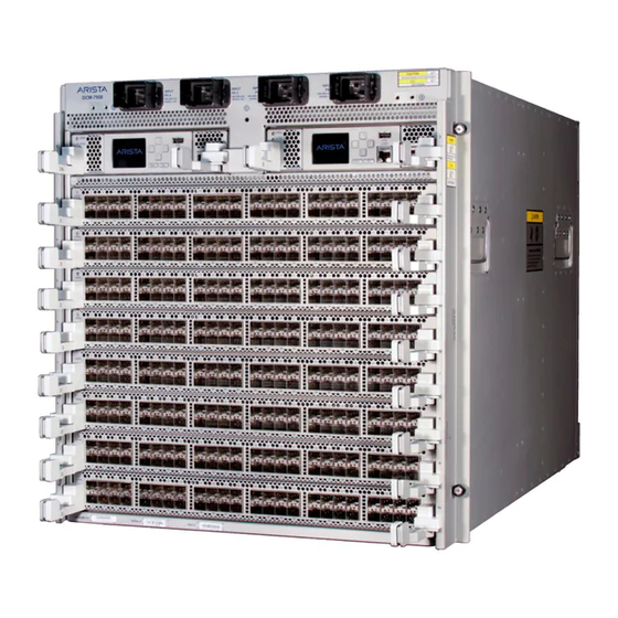
Page 28: Appendix D Front Panels
Appendix D: Front Panels Appendix D Front Panels This appendix displays the front panel of all switches covered by this guide. DCS-7508 Front Panel with Supervisor-1 DCS-7504 Front Panel with Supervisor-1 Arista Networks Copyright 2013... - Page 29 Appendix D: Front Panels DCS-7508 Front Panel with Supervisor-E and E-Series Linecards DCS-7504 Front Panel with Supervisor-E and E-Series Linecards Modular Switch Quick Start Guide PDOC-00015-04...
-
Page 30: Appendix E Rear Panel
Appendix E: Rear Panel Appendix E Rear Panel This appendix displays the rear panel of all switches covered by this guide. DCS-7508 Rear Panel with DCS-7508-FAN Modules DCS-7504 Rear Panel with DCS-7504-FM Modules Arista Networks Copyright 2013... - Page 31 Appendix E: Rear Panel DCS-7508 Rear Panel with DCS-7508E-FM Modules DCS-7504 Rear Panel with DCS-7504E-FM Modules Modular Switch Quick Start Guide PDOC-00015-04...
-
Page 32: Appendix F Line Cards
Appendix F: Line Cards Appendix F Line Cards This appendix displays the line cards supported by modular switches covered by this guide. DCS-7548S-LC DCS-7500E-36Q-LC DCS-7500E-72S-LC DCS-7500E-48S-LC Arista Networks Copyright 2013...
Need help?
Do you have a question about the DCS-7508 and is the answer not in the manual?
Questions and answers