Table of Contents
Advertisement
Quick Links
Advertisement
Table of Contents

Related Manuals for Sensitron MULTISCAN 8+


Summary of Contents for Sensitron MULTISCAN 8+
- Page 1 MULTISCAN 8+ ATEX and SIL 1 certified MANUAL FOR INSTALLATION AND USE SENSITRON S.r.l. Viale della Repubblica, 48 20010 CORNAREDO MI - Italy Tel: + 39 02 93548155 Fax: + 39 02 93548089 E-MAIL: sales@sensitron.it MT4412E Rev.3 15/10/2019 Page 1 of 30...
- Page 2 Technical manual MULTISCAN 8+ Warning THIS MANUAL MUST BE CAREFULLY READ BY ALL PERSONS WHO ARE OR WILL BE RESPONSIBLE FOR INSTALLING, USING OR SERVICING THIS PRODUCT. Like any equipment, this product will perform as designed only if installed, used and serviced in accordance with the manufacturer’s instructions. OTHERWISE, IT COULD FAIL TO PERFORM AS DESIGNED AND PERSONS WHO RELY ON THIS PRODUCT FOR THEIR SAFETY COULD SUFFER SEVERE PERSONAL INJURY OR DEATH.
- Page 3 Technical manual MULTISCAN 8+ THIS TECHNICAL MANUAL DESCRIBES THE PRODUCT IN ITS COMPONENTS, THE INSTALLATION AND THE OPERATION OF THE SYSTEM. THE CONFIGURATION SOFTWARE IS NOT INCLUDED, SO PLEASE REFER TO THE PROPER MANUAL. MT4412E Rev.3 15/10/2019 Page 3 of 30...
-
Page 4: Table Of Contents
Technical manual MULTISCAN 8+ INDEX INTRODUCTION ........................... 5 1.1) ............. 6 LOCK DIAGRAM SYSTEM WITH ULTISCAN CENTRAL UNIT 1.2) ......................6 ECHNICAL SPECIFICATIONS INSTALLATION ............................ 7 2.1) ......................7 SSEMBLY AND CONNECTIONS 2.1.1) ................... 8 NIT DIAGRAM AND PART IDENTIFICATION 2.1.2) ..................... -
Page 5: Multiscan 8
INTRODUCTION The highly innovative and versatile MULTISCAN 8+ central units the ideal solution for small systems with up to 16 gas detectors. The system provides for the direct connection of 8 detectors to the central unit (4-20mA) and to additional 8 detectors that can be connected directly to the RS485 bus or via a remote module with 8 x STG/IN8-S inputs. -
Page 6: Block Diagram System With Multiscan 8+ Central Unit
1.1) Block diagram system with Multiscan 8+ central unit LOOP Rs485 16 relay option: the detectors could be connected MULTISCAN 8+ directly on the loop in daisy-chain mode (1) RILEVATORI GAS ANALOGICI 4-20 mA / 4-20 mA ANALOG GAS DETECTORS (2) MODULO 8 INGRESSI ANALOGICI ST.G/IN8-S / ANALOG 8 INPUT MODULE ST.G/IN8-S (3) CAVO 2 FILI TWISTATI PER Rs485 + 2 FILI PER ALIMENTAZIONE (12-24 Vdc) /... -
Page 7: Installation
INSTALLATION 2.1) Assembly and connections Remove the 4 screws at the 4 corners of the box and remove the front part of the central unit box. It is now possible to choose where to place the cables. We recommend placing the cable for entry by using a suitable cable press. -
Page 8: 1) Unit Diagram And Part Identification
2.1.1) Unit diagram and part identification 1- Power Supply (27 Vdc 4A) 5- Relay outputs (6) 2- 2 x 12V 7Ah batteries (not included) 6- 8 inputs, 4-20mA 3- RS232 serial port and USB 7- RS485 bus connection 4- RS485 serial card 8- Central unit card Fig. -
Page 9: 2) Central Unit Card Layout
2.1.2) Central unit card layout Rs232 FOR PC SWITCH USB / SERIAL USB FOR PC CONNECTION (OPTIONAL) Fig. 2.1.2) Central unit card layout MT4412E Rev.3 15/10/2019 Page 9 of 30... -
Page 10: 3) 16-Relay Card Layout (Optional)
2.1.3) 16-relay card layout (optional) 12Vdc POWER SUPPLY SOLO CENTR. Pl4+ / ONLY Pl4+ PANEL CONNECTORS FOR MULTISCAN 8+ CONTROL PANEL FOR Pl4+ CONTROL PANEL (PL4/ESP BOARD REQUIRED) JUMPER FOR NORMALLY ENERGIZED RELAY NORMALLY NOT ENERGIZED RELAY C NC NO C NC NO C NC NO C NC NO... - Page 11 2.1.4) Setting of the communication bus, RS232 PC serial and central unit language The series of D2 dip-switches are used to set the following: • Baud Rate (communication speed) and RS485 bus protocol with field devices (detectors and IN/OUT modules). •...
-
Page 12: Field Device Connections
Dip-switch 1: Baud Rate Bus RS485 Position Bus communication speed Detector and module compatibility Smart “S” gas detectors; ST.G/IN8-S and 115200 ST.G/OUT16-S modules Smart “3G” gas detectors; ST.G/IN8-S and 9600 ST.G/OUT16-S modules Dip-switches 2 and 3: RS485 bus communication protocol Detector and module Sw 2 Sw 3... -
Page 13: 1) Detector Connection
-) The RS485 serial bus must be connected with an EIA RS 485 connection wire: No. 2 wires with 0.22/0.35 mm2 section with shield (TWISTED PAIR). Nominal capacity between conductors < 50 pF/m, nominal impedance 120 ohm. Total line length with this type of connection must not exceed 1,000 metres. - Page 14 Detectors with 4-20mA output Detectors with 4-20mA analogue output are either connected to the central unit, directly on the main board or via one remote 8-input STG/IN8-S module. The module may be connected remotely to the central unit. For connection, a detector with a 4-20mA analogue output requires a 3-conductor cable: 2 conductors for the power supply (usually from 12 to 28 Vdc - refer to the gas detector technical manual) and one conductor for the 4-20mA signal.
- Page 15 Detectors with RS485 output Gas detectors provided with RS485 serial communication are connected directly to the RS485 bus of the MULTISCAN 8+ central unit. The STG/IN8-S input module and STG/OUT16-S output module are also connected to the RS485 bus. 4 conductors are needed for this type of connection: 2 for the RS485 serial and 2 for the power supply of devices.
- Page 16 Fig. 2.2.1 c) Direct connection of detectors on the RS485 bus MT4412E Rev.3 15/10/2019 Page 16 of 30...
- Page 17 SCHEDA CENTRALE / PANEL MAIN BOARD STG/IN8 MODULE + s - 4-20mA GAS DETECTOR (up to 8) Fig. 2.2.1 d) Detector connection by STG/IN8-S MT4412E Rev.3 15/10/2019 Page 17 of 30...
-
Page 18: Stg/In8-Sremote Input Modules
2.3) STG/IN8-S remote input modules STG/IN8-S remote modules are field mounted and connected to the central unit via RS485 buses. They are used to connect 8 x 4-20mA analogue gas detectors. Each module must be addressed using the rotary switches on the PCB. The address must be univocal and between 1 and 255 (1-247 for Modbus protocol). -
Page 19: Stg/Out16-Sremote Output Modules
2.4) STG/OUT16-S remote output modules STG/OUT16-S remote modules are field mounted and connected to the central unit via RS485 buses. They provide 16 Open Collector outputs (negative switch) with a programmable function for the remote activation of sirens, solenoid valves, relays, etc. Up to 2 8-relay boards can be connected to each STG/OUT16-S module, transforming the output from Open Collector to a voltage-free exchange contact. -
Page 20: 1) Stg/8Rel Relay Expansion Board
2.4.1) STG/8REL relay expansion board The STG/8REL 8-relay expansion board converts the O/C outputs of the STG/OUT16-S output module into voltage-free exchange contacts. Up to two relay boards can be connected to each output module. A relay board is directly connected to the output module (J1 connector) and a second relay board is connected to the former. - Page 21 Example If the two switches are positioned as above, RSW2 on 0 and RSW1 on D, the corresponding address in decimals is 13 (see table 1) If the address switches are set in this mode, RSW2 at 0 and RSW1 at D, the corresponding address in decimal numbers would be 13 (see table 1).
-
Page 22: Programming From Apc
2.5) Programming from a PC The Multiscan 8+ central unit is fully programmable from a personal computer by means of special software. The software has been designed for simple and fast programming. Connection to the PC takes place via the RS232 serial port or USB, available on the main board of the central unit. -
Page 23: Tcp/Ip Optional Module
• Remote management of the central unit, via third party software, by using the ModBus protocol • Remote management of the central unit, via a monitoring software made by Sensitron (available in the future) For technical features and use of TCP/IP module, please consult the product documentation. -
Page 24: Power On
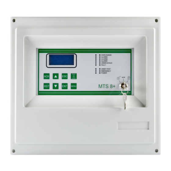
3.1) Power ON After ensuring correct installation of the system, the Multiscan 8+ central unit can be switched on. When first switched on, after the “Warm Up” time (3 minutes by default), the display will be blank as the central unit needs to be programmed. Fig. - Page 25 3.2) System status The central unit communicates with the operator by means of the LCD display and LEDs on the front panel. Different information is displayed during different states of the system. A few general rules apply at any level as follows: On the front is a key switch with three positions, which determine system operation Closed padlock: it is not possible to operate the central unit ACK it is possible to acknowledge the event by silencing the buzzer of...
- Page 26 ALARM The Alarm status is activated when one or more gas detectors measure a gas concentration higher than the alarm threshold set during the configuration of the central unit. Programming of alarm thresholds and other parameters of each channel can be set during PC configuration.
- Page 27 1. Short circuit, open circuit, or channel malfunction 2. Removal or malfunction of a ST.G/IN8 or ST.G/OUT16 module 3. Detector in Under-scale (signal below "0") 4. Detector in over-range (signal over 100% of the scale) Fig. 3.2.1.d) Screen in Fault status By pressing the Enter key with a fault event selected, a screen opens that shows the event details: Fig.
-
Page 28: System Status Menu
Warning: a gas detector in OFF status does not generate an alarm. EMERGENCY This is a particular malfunction status that can occur for the following two reasons: • Malfunctioning of the Vcc power supply of the central unit • Lack of 230 Vac primary power supply 3.3) MENU In normal status, the list of gas detectors managed by the central unit appears on the... - Page 29 It is possible to perform 3 operations for active events: - press ENT per additional details about the event - press ACK to acknowledge the event and silence the buzzer of the central unit - press RST (Reset) to restore the central unit to its normal status (this is only possible if ACK was pressed before and if the gas detector is no longer in the alarm and/or fault status) When an event occurs (alarm or fault), the buzzer of the central unit will sound and the...
- Page 30 The aforementioned information does not bind the manufacturer, which reserves the right to make any changes that it deems useful for product improvement. For further information contact: Tel: +39 02 935.48.155 Sensitron S.r.l. Fax: +39 02 935.48.089 e-mail: sales@sensitron.it MT4412E Rev.3 15/10/2019...
Need help?
Do you have a question about the MULTISCAN 8+ and is the answer not in the manual?
Questions and answers