Table of Contents
Advertisement
Quick Links
Advertisement
Table of Contents

Related Manuals for Sensitron MULTISCAN++/S1-32B


Summary of Contents for Sensitron MULTISCAN++/S1-32B
- Page 1 I N S T A L L A T I O N A N D U S E M A N U A L SENSITRON S.r.l. Viale della Repubblica, 48 20010 CORNAREDO MI - Italy Tel: + 39 02 93548155 Fax: + 39 02 93548089 E-MAIL: sales@sensitron.it...
- Page 2 FAIL TO PERFORM AS DESIGNED AND PERSONS WHO RELY ON THIS PRODUCT FOR THEIR SAFETY COULD SUFFER SEVERE PERSONAL INJURY OR DEATH. The warranties made by Sensitron s.r.l. with respect to this product are voided if the product is not installed, used and serviced in accordance with the instructions in this user guide.
- Page 3 Technical Manual MULTISCAN++S1/32B THIS TECHNICAL MANUAL DESCRIBES THE PRODUCT IN ITS COMPONENTS, THE INSTALLATION AND THE OPERATION OF THE SYSTEM. THE CONFIGURATION SOFTWARE IS NOT INCLUDED, SO PLEASE REFER TO THE PROPER MANUAL. MT3896E Rev.1 15/10/2019 Pagina 3 di 45...
-
Page 4: Table Of Contents
Technical Manual MULTISCAN++S1/32B INDEX INTRODUCTION ........................... 5 1.1) ........................6 YSTEM CONFIGURATION 1.2) ......................6 ECHNICAL SPECIFICATIONS INSTALLATION ............................ 7 2.1) ..................7 OUNTING AND ELECTRICAL CONNECTIONS 2.1.1) ................... 8 IAGRAM AND PART IDENTIFICATION 2.1.2) ....................... 9 AYOUT SCHEDA CENTRALE 2.1.3) .................... -
Page 5: Introduction
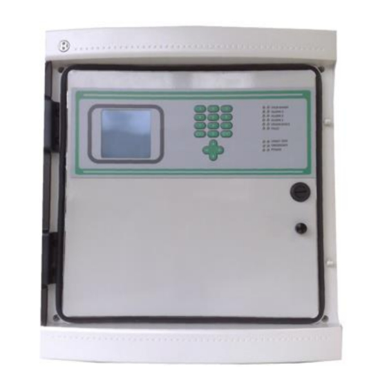
INTRODUCTION The MULTISCAN++S1/32B is a gas control unit designed to offer the widest range of flexibility required by the market. The control panel is based on a powerful microprocessor which provides a wide range of self- diagnostic procedures to detect and locate possible faults. Extremely flexible and reliable, it can manage up to 40 detectors, 8 directly connectable to the panel and 32 gas detectors on the 2 serial lines the panel comes complete with. -
Page 6: System Configuration
1.1) System configuration 16 O/C BUS 1 BUS 2 E’ possibile realizzare il sistema con 2 BUS aperti oppure 1 Loop chiuso It is possible to make the system with 2 oper BUS or 1 closed Loop MULTISCAN ++ S1 32B CONTROL PANEL (1) RILEVATORI GAS ANALOGICI 4-20 mA / 4-20 mA ANALOG GAS DETECTORS (2) MODULO 8 INGRESSI ANALOGICI ST.G/IN8-S / ANALOG 8 INPUT MODULE ST.G/IN8-S... -
Page 7: Installation
INSTALLATION 2.1) Mounting and electrical connections After opening the transparent unit door, also open the front panel by rotating the black lock to UNLOCK. Disconnect the two wires that lead from the unit board (JP47 and JP51 connectors) to the bottom of the box for power connections (see fig. -
Page 8: 1) Diagram And Part Identification
Power Supply BATTERIES Fig. 2.1 b) Power supply 2.1.1) Diagram and part identification Box version 1- Power Supply (27 Vdc 4A) 5- Relay outputs (8) 2- 2 x 12V 7Ah batteries (not included) 6- 8 detectors 4-20 mA inputs 3- RS232 serial port (PC connection) 7- Bus RS485 bus connections 4- RS485 serial boards 8- Panel main board... -
Page 9: 2) Layout Scheda Centrale
2.1.2) Layout scheda centrale Fig. 2.1.2) Layout main board MT3896E Rev.1 15/10/2019 Pagina 9 di 45... -
Page 10: 3) Power Supply Connections
2.1.3) Power supply connections Selezionare 110/220V con 110/220V is selected by switch lo switch all’interno. Verificare Before power ON please check 100-120 Vac prima di dare alimentazione, Input voltage avoiding damage 200-240 Vac per evitare danneggiamenti. select the input voltage 27,6 Vdc/ 4 A power supply Fig. -
Page 11: Field Device Connections
Dip-switch 1: Baud Rate Bus RS485 Positione Velocità comunicazione bus Detector and Module compatibility Smart “S” gas detectors and ST.G/IN8-S / 115.200 ST.G/OUT16-S modules Smart “3G” gas detectors and ST.G/IN8-S / 9.600 ST.G/OUT16-S modules Dip-switches 2 and 3: RS485 bus communications protocol Compatibilità... -
Page 12: 1) Detectors Connection
4 conductors are required for device connections: 2 for the RS485 serial bus and two for power supply. For this reason, two different wires must be used or a single wire that has suitable characteristics, described below. -) The RS485 serial bus must be connected with an EIA RS 485 connection wire: No. 2 conductors with 0.22/0.35 mm section + shield (TWISTED PAIR). - Page 13 Detectors with 4-20mA output Detectors with 4-20mA analog output are connected to the unit via remote 8-input modules STG/IN8-S. The modules are connected on the panel's bus to be field mounted far from the control panel. A 4-20mA transmitter requires a 3-core wire for connections: 2 wires for power supply (usually 12 to 28 Vdc but refer to the gas detector technical manual) and one wire for the 4-20mA signal.
- Page 14 Detectors with RS485 output Detectors with RS485 digital outputs are directly connected to the RS485 bus. 4 wires are required in this type of connection: 2 for the RS485 serial bus and 2 for device power supply. For this reason we suggest you use two different wires or a single wire with suitable features as described below.
- Page 15 Fig. 2.2.1 c) RS485 bus devices connection (Open bus) MT3896E Rev.1 15/10/2019 Pagina 15 di 45...
- Page 16 Fig. 2.2.1 d) RS485 bus devices connection (Closed bus) MT3896E Rev.1 15/10/2019 Pagina 16 di 45...
-
Page 17: Stg/In8-Sremote Input Module
2.3) STG/IN8-S remote input module STG/IN8-S remote modules are field mounted and are connected to the panel via RS485 buses. They are used to connect 8 x 4-20mA analog gas detectors. Each module must be addressed using the rotary switches on the PCB. The address must be univocal and between 1 and 255. -
Page 18: Stg/Out16-Sremote Output Module
2.1) STG/OUT16-S remote output module STG/OUT16-S remote modules are field mounted and connected to the panel via RS485 buses. They provide 16 Open Collector outputs (negative switch) with programmable functions to remotely trigger Sirens, Solenoid valves, Relays, etc. Each STG/OUT16-S module can be connected to up to 2 boards of 8 relays that convert the Open Collector output to a powerless exchange contact. -
Page 19: 1) Stg/8Rel Relay Expansion Board
2.1.1) STG/8REL relay expansion board The STG/8REL 8-relay expansion board converts STG/OUT16-S O/C outputs into voltage free changeover contact. Up to two relay boards can be connected to each output module. A relay board is directly connected to the output module (J1 connector) and a second relay board is connected to the first. - Page 20 Example Se i due commutatori sono posizionati come sopra, RSW2 su 0 ed RSW1 su D, l’indirizzo corrispondente in decimale è 13 (vedi tabella 1) If the address switches are set in this manner, RSW2 at 0 and RSW1 at D, the corresponding address in decimal number would be 13 (see table 1).
-
Page 21: 3) Detector Identification
2.1.3) Detector identification Every detector connected to the control panel is identified by a code which allows its configuration and contains all the principle data required to physically identify it. For example: Numero bus (1-4) (bus number (1-4)) 02001 Indirizzo modulo IN/8 o rilevatore gas (Module IN/8 or detector address) da 0 a 255 (from 0 to 255) Posizione rilevatore da 01 a 08 se modulo... -
Page 22: System Power Up And Operation
• Remote management of the control panel, via third parties supervising software, by using the Modbus protocol • Remote management of the control panel, via a supervising software made by Sensitron (future availability) For technical features and use of TCP/IP module, please consult the product documentation. -
Page 23: Power On
3.1) Power ON After ensuring correct installation of the MULTISCAN++S1/32B, the unit can be switched on. When first switched on, after the “Warm Up” time (3 minutes by default), the display will show an empty picture without any indication because, at the first switch ON, the control panel needs programming. -
Page 24: System States And Operation
3.2) System states and operation The LCD display provides the user with details about the various system states. A few general rules apply at any level as follows: • Should there be a list displayed, the page scrolling can be done using the UP/DOWN arrow keys. - Page 25 ALARM When one or more detectors exceed the preset thresholds, the control unit enters in the Alarm status. The alarm condition will be activated according to the settings for each and every input In the alarm window the following info is available: Fig.
- Page 26 Fig. 3.2.1.c) ALARM details screen. At any access level, by selecting in the main window the 1—Menu and than ACTIVE EVENTS sub menu, it is possible to see the gas detectors in alarm state, or not yet reset. FAULT The fault condition will be activated in the following situations: 1.
- Page 27 Fig. 3.2.1.e) FAULT details screen TEST/MAINTENANCE This state is meant for testing and maintenance purpose. This testing function requires an operation sequence and can be activated for each detector being connected. An user with the OPERATOR or MAINTENANCE level cannot put under TEST/MAINTENANCE more than 50% of the system’s channels and outputs.
-
Page 28: User Levels
EMERGENCY This is a special defined state into which the system switches when one of the following two situations occurs: 1- Malfunctioning of the control panel power supply 2- AC Fail (230 Vac or 110 Vac missed) 3.3) User levels The system offers three user levels and, depending on these, various options are available. -
Page 29: 1) Operator Level
3.3.1) OPERATOR LEVEL The “Operator” user may only see the system’s configuration. He may browse the system through channels and relays. The “Operator” cannot put under Test or get out of Test mode any detector or parts of the system, nor he can Unset parts of the system, or Set parts of the system previously unset. -
Page 30: 2) Maintenance Level
3.3.2) MAINTENANCE level The “Maintenance” level is the middle user level. Like the “Operator” user, the “Maintenance” user may see the system’s configuration. He may also browse the system through channels and relays. Unlike the “Operator” the “Maintenance” user may also put under Test or take out of Test mode any systems part, and he can Unset parts of the system, or Set parts of the system previously unset. -
Page 31: Active Events
Operator level (O) Maintenance level (M) Engineer level (E) ACTIVE EVENT (*) ACTIVE EVENT (*) ACTIVE EVENT (*) EVENT LOG EVENT LOG EVENT LOG PRINT SET PRINTER MODE SET PRINTER MODE ABORT PRINT PRINT PRINT SYSTEM INFO ABORT PRINT ABORT PRINT SYSTEM INFO SYSTEM INFO (*) available just if some active event is present... - Page 32 Fig. 3.5.1 b) Active Events screen with alarm only Or in case just Fault situation is present: Fig. 3.5.1 c) Active events screen with fault only In case of a new event, the screen will automatically switch to the Active Events list and the buzzer will sound.
-
Page 33: 2) Event Log
By pressing 1 ACK with the cursor on the active event, this will get acknowledged. There are two situations: 1. the user is already logged in. In this case by pressing 1 ACK the screen image will simply refresh and an “X” mark will appear on the “A”... - Page 34 Fig. 3.5.2 a) Event detail screen - Using the up/down arrow keys one may scroll through the list. - Using the keys 2 and 4, one may refine the search - Pressing the ESCAPE key instead will switch back to the main window. Should 3 minutes pass without any key pressed, the view switches to the Operator main window.
-
Page 35: 3) Print
complete end date. In the end, pressing ENTER, the window will next show only the selected period events. Using the up/down arrow keys one may scroll through the new list. To exit this view and go back to the main window press ESCAPE key. Filter In any of the events screens, by pressing the key 2 Filter, it is possible to enter in a sub-menu of the Event Log. -
Page 36: 4) System Info
pressing ENT one starts the printout of the system detector list with all the programming data (Zone, detector description, Alarm levels etc.). ABORT PRINT To stop and cancel the printout SET PRINTER MODE (Users level “M” and “E”) This parameter is used to select the print mode. ON REQUEST In this case, the control panel only prints specific details (Event Log, detector list etc.) at the user’s request, in the different menu. -
Page 37: 2-Logout
Fig. 3.5.3) System Info window 3.6) 2-LOGOUT From the normal mode screen, pressing 2-LOGOUT key, the actual user will logout. 3.7) 4-LOGIN Pressing 4-LOGIN key a login window will ask for the user password, to allow entering one of the three user levels: OPERATOR, MAINTENANCE or ENGINEER level (see the related chapter 3.3 User levels). -
Page 38: 3-System
be displayed what user level is it: “O” for Operator, “M” for Maintenance and “E” for Engineer. Fig. 3.7 b) NORMAL state screen with the “E” in the right and upper corner 3.8) 3-SYSTEM In the main window in Normal mode, at any user level, one may view the system’s configuration details, by pressing 3-System. - Page 39 Fig. 4.8 1 ) Zones screen and options available pressing 3-Zone SET / UNSET Pressing 3-Zone in the Maintenance or the Engineer level it is possible to Set or Unset parts of the system. The number of channels that may be Unset will never exceed 50% of the total channels/relays number or 64 channels/relays, whatever happens first.
-
Page 40: 2) Modules
In the main window, close to each channel (detector) its status will appear: TST (under TEST) or FLT (fault). Now it will be easy to verify, directly in field, which modules or detectors are not communicating on the RS485 bus and so fix the issues. When these fault are fixed, the channels status in the main window will change from FLT to TEST. - Page 41 Put in Test/Maintenance and take out of Test/Maintenance the selected relay SET / UNSET Pressing 3-Relay in the Maintenance or the Engineer level it is possible to Set or Unset parts of the system. An user with the MAINTENANCE level cannot UNSET more than 50% of the system’s channels and relays.
-
Page 42: 4) Detectors (Channels)
This screen is the same for “Operator” and “Maintenance” level, allowing only to view the relay configuration details. Fig. 3.8.3 c) Screen with the output operative details Unlike the above, this screen seen as “Engineer” level, allows changing the relay’s timings. - Page 43 Put in Test/Maintenance and take out of Test/Maintenance the selected channel SET / UNSET Pressing 3-Channel in the Maintenance or the Engineer level it is possible to Set or Unset parts of the system. An user with the MAINTENANCE level cannot UNSET more than 50% of the system’s channels and relays.
- Page 44 Fig. 3.8.3 c) Detector details screen in “Engineer“ level Unlike the above, this screen seen as “Engineer” level, allows changing the Detector’s details. See chapter 4-PC Configuration for more details. MT3896E Rev.1 15/10/2019 Pagina 44 di 45...
- Page 45 The above information does not make the manufacturer liable, and the manufacturer reserves the right to make any changes that it retains will be useful to improve the product. For further information contact: Tel: +39 02 935.48.155 Sensitron S.r.l. Fax: +39 02 935.48.089 e-mail: sales@sensitron.it MT3896E Rev.1 15/10/2019...
Need help?
Do you have a question about the MULTISCAN++/S1-32B and is the answer not in the manual?
Questions and answers