
Related Manuals for Aerotech ECO115SL Series


Summary of Contents for Aerotech ECO115SL Series
-
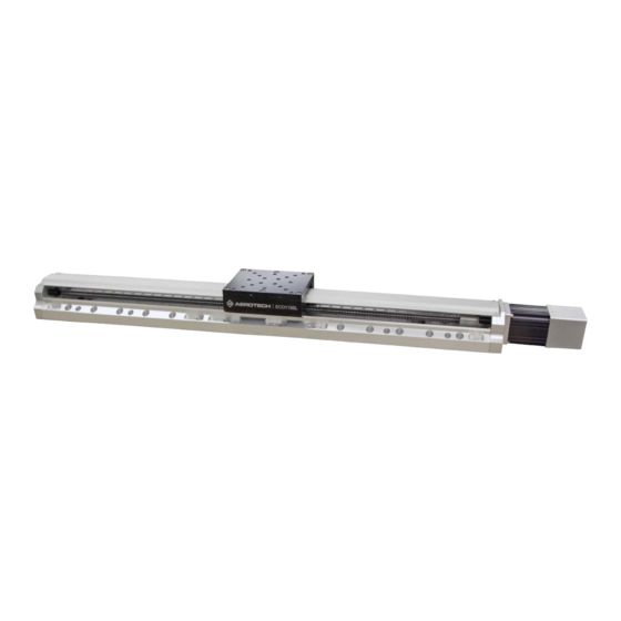
Page 1: Eco115Sl Series Mechanical Bearing, Ball-Screw Stage
ECO115SL Series Mechanical Bearing, Ball-Screw Stage HARDWARE MANUAL Revision 2.00... - Page 2 This manual contains proprietary information and may not be reproduced, disclosed, or used in whole or in part without the express written permission of Aerotech, Inc. Product names mentioned herein are used for identification purposes only and may be trademarks of their respective companies.
-
Page 3: Table Of Contents
ECO115SL Hardware Manual Table of Contents Table of Contents ECO115SL Series Mechanical Bearing, Ball-Screw Stage Table of Contents List of Figures List of Tables Safety Procedures and Warnings EU Declaration of Incorporation Chapter 1: Overview 1.1. Environmental Specifications 1.2. Accuracy and Temperature Effects 1.3. -
Page 4: List Of Figures
Attach the Coupling Adapter to the Motor Shaft Figure 4-5: Attach the Motor the Stage Figure 4-6: Tighten the Shaft Coupling to the Drive Screw Figure 4-7: Foldback Motor Cover Removal Figure 4-8: Foldback Motor Part Callouts Figure 4-9: Lubricate the Pulley Flanges www.aerotech.com... -
Page 5: List Of Tables
List of Tables Table 1-1: Model Numbers and Ordering Options Table 1-2: Environmental Specifications Table 1-3: ECO115SL Series Specifications (-050 to -250) Table 1-4: ECO115SL Series Specifications (-300 to -600) Table 2-1: Stage Mounting Surface Flatness Requirement Table 2-2: Stage to Mounting Surface Hardware... - Page 6 List of Tables ECO115SL Hardware Manual This page intentionally left blank. www.aerotech.com...
-
Page 7: Safety Procedures And Warnings
To find the newest information about this product, refer to www.aerotech.com. If you do not understand the information in this manual, contact Aerotech Global Technical Support. IMPORTANT: This product has been designed for light industrial manufacturing or laboratory environments. - Page 8 DANGER: System travel can cause crush, shear, or pinch injuries. Restrict access to all motor and stage parts while your system is connected to a power source. Do not put yourself in the travel path of machinery. Motors are capable of very high speeds and acceleration rates. www.aerotech.com...
- Page 9 Use it to shut down the drive if the motor overheats. Make sure that the product is securely mounted before you operate it. Use care when you move the ECO115SL or you could negatively affect the performance of it. WARNING: Securely mount and position all system cables. www.aerotech.com...
- Page 10 Safety Procedures and Warnings ECO115SL Hardware Manual This page intentionally left blank. www.aerotech.com...
-
Page 11: Eu Declaration Of Incorporation
ECO115SL Hardware Manual EU Declaration of Incorporation EU Declaration of Incorporation Manufacturer Aerotech, Inc. 101 Zeta Drive Pittsburgh, PA 15238-2811 herewith declares that the product: ECO115SL Linear Stage is intended to be incorporated into machinery to constitute machinery covered by the Directive 2006/42/EC as amended;... - Page 12 EU Declaration of Incorporation ECO115SL Hardware Manual This page intentionally left blank. www.aerotech.com...
-
Page 13: Chapter 1: Overview
Foldback Kit with Brake for .375 Inch Diameter Shaft NEMA 23 Motor Motor Orientation (Optional) Bottom cable exit (optional orientation) Left side cable exit (standard orientation) Top cable exit (optional orientation) Right side cable exit (optional orientation) Right side foldback (standard orientation) Left side foldback (optional orientation) www.aerotech.com... - Page 14 XZ or YZ assembly with L-bracket; 5 arc second orthogonality; alignment to within 5 µm ALIGN-PA5Z orthogonality for short travel stages Right angle L-bracket for 50 mm, 100 mm, and 150 mm travels only; HDZ115 NOTE: Requires a tabletop when mounting to an ECO series stage www.aerotech.com...
-
Page 15: Environmental Specifications
1.2. Accuracy and Temperature Effects The accuracy specification of ECO115SL series stages is measured 25 mm above the table with the stage in an unloaded condition. The stage is assumed to be fully supported by a mounting surface meeting or exceeding the specification in Section 2.3. -
Page 16: Basic Specifications
6. Specifications are for single-axis systems measured 25 mm above the tabletop; performance of multi-axis system is payload and workpoint dependent. Consult the Aerotech factory for multi-axis or non-standard applications. 7. Specifications listed are non-foldback kit options. Contact the factory for specifications when a foldback kit (-FBx) is used. -
Page 17: Table 1-4: Eco115Sl Series Specifications (-300 To -600)
6. Specifications are for single-axis systems measured 25 mm above the tabletop; performance of multi-axis system is payload and workpoint dependent. Consult the Aerotech factory for multi-axis or non-standard applications. 7. Specifications listed are non-foldback kit options. Contact the factory for specifications when a foldback kit (-FBx) is used. -
Page 18: Vacuum Operation
Teflon cables. Aerotech recommends that customers bake out vacuum systems when first installing them in the vacuum chamber. Contact Aerotech to discuss your application and the recommended bakeout procedure. -
Page 19: Chapter 2: Installation
Before you operate the stage, let it stabilize at room temperature for at least 12 hours. This will ensure that all of the alignments, preloads, and tolerances are the same as they were when they were tested at Aerotech. Each stage has a label listing the system part number and serial number. These numbers contain information necessary for maintenance or system hardware and software updates. -
Page 20: Dimensions
2.2. Dimensions ECO115SL Hardware Manual 2.2. Dimensions Figure 2-1: ECO115SL Dimensions www.aerotech.com... -
Page 21: Figure 2-2: Tabletop Accessory Dimensions (-Tt3 Option)
ECO115SL Hardware Manual 2.2. Dimensions Figure 2-2: Tabletop Accessory Dimensions (-TT3 Option) www.aerotech.com... -
Page 22: Figure 2-3: Z-Axis Bracket Dimensions
2.2. Dimensions ECO115SL Hardware Manual Figure 2-3: Z-Axis Bracket Dimensions www.aerotech.com... -
Page 23: Securing The Stage To The Mounting Surface
Refer to Section 2.2. for mounting locations and dimensions. Table 2-2: Stage to Mounting Surface Hardware Mounting Hardware Typical Screw Torque M6 x 18 mm (or 1/4" x 3/4") SHCS with flat washers 7 N·m [5 ft·lb] www.aerotech.com... -
Page 24: Attaching The Payload To The Stage
If you start the ECO115SL without a payload, the servo gains provided by Aerotech with the shipment may not be appropriate and servo instability can occur. Refer to the controller help file for tuning assistance. -
Page 25: Figure 2-4: Stage Orientations
ECO115SL Hardware Manual 2.4. Attaching the Payload to the Stage Figure 2-4: Stage Orientations Figure 2-5: Cantilevered Load Capability www.aerotech.com... -
Page 26: Figure 2-6: Load Torque Equation
2.4. Attaching the Payload to the Stage ECO115SL Hardware Manual The approximate amount of torque required to turn the ball screw of ECO115SL series stages can be found from Figure 2-7 or the following equation: (AxialLoad) (LeadofScrew) Torque π (Efficiency) -
Page 27: Chapter 3: Electrical Installation
Electrical installation requirements will depend on the ordered product options. Installation instructions in this section are for Aerotech stages equipped with standard Aerotech motors intended for use with an Aerotech motion control system. Contact Aerotech for further information on products that are otherwise configured. -
Page 28: Motor And Feedback Connectors
Stages equipped with standard motors and encoders come from the factory completely wired and assembled. IMPORTANT: Refer to the other documentation accompanying your Aerotech equipment. Call your Aerotech representative if there are any questions on system configuration. IMPORTANT: If using standard Aerotech motors and cables, motor and encoder connection adjustments are not required. -
Page 29: Table 3-1: Brushless Motor Connector Pinout [-M1 To -M8]
Reserved Reserved Reserved Reserved Reserved Frame Ground (motor protective ground) Table 3-2: Mating Connector Part Numbers for the Brushless Motor Connector Mating Connector Aerotech P/N Third Party P/N Backshell ECK00656 Amphenol #17E-1726-2 Sockets [QTY. 4] ECK00659 ITT Cannon #DM53744-6 Connector... -
Page 30: Table 3-5: Brushless Motor Feedback Connector Pinout [-M1 To -M8]
Common ground Reserved Reserved Reserved Reserved Brake + (with Brake Option) Table 3-6: Mating Connector Part Numbers for the Brushless Motor Feedback Connector Mating Connector Aerotech P/N Third Party P/N 25-Socket D-Connector ECK00300 FCI DB25S064TLF Backshell ECK00656 Amphenol 17E-1726-2 www.aerotech.com... -
Page 31: Table 3-7: Stepper Motor Feedback Connector Pinout [-M9 And -M10]
SIN+ (Encoder Sine+) SIN- (Encoder Sine-) Reserved Common Common Reserved Reserved Reserved Reserved Table 3-8: Mating Connector Part Numbers for the Stepper Motor Feedback Connector Mating Connector Aerotech P/N Third Party P/N 25-Socket D-Connector ECK00300 FCI DB25S064TLF Backshell ECK00656 Amphenol 17E-1726-2 www.aerotech.com... -
Page 32: Table 3-9: Limit Connector Wiring
+Limit/CW (Positive/Clockwise Travel Limit) Home Limit -Limit/CCW (Negative/Counterclockwise Limit) Reserved Common ground Reserved Reserved Table 3-10: Mating Connector Part Numbers for the Limit Connector Mating Connector Aerotech P/N Third Party P/N 9-Pin D-Connector ECK00340 FCI DE09S064TLF Backshell ECK01021 Amphenol 17E-1724-2 www.aerotech.com... -
Page 33: Motor And Feedback Wiring
ECO115SL Hardware Manual 3.2. Motor and Feedback Wiring 3.2. Motor and Feedback Wiring Shielded cables are required for the motor and feedback connections. Figure 3-1: Brushless Motor and Feedback Wiring [-M1 through -M8 Options] www.aerotech.com... -
Page 34: Figure 3-2: Stepper Motor And Feedback Wiring [-M9 And -M10 Options]
3.2. Motor and Feedback Wiring ECO115SL Hardware Manual Figure 3-2: Stepper Motor and Feedback Wiring [-M9 and -M10 Options] www.aerotech.com... -
Page 35: Motor And Feedback Specifications
Note: If the ECO115SL is driven beyond the electrical limit, it will encounter a mechanical stop. Impacting the mechanical stop could cause damage to the stage even at low speeds. Table 3-15: Brake Specifications Specification Supply Voltage 24 VDC Supply Current (typical) 250 mA (current required to release the brake and allow motion) www.aerotech.com... -
Page 36: Table 3-16: Eco115Sl Motor Specifications (Bms60)
5. All performance and electrical specifications ±10% 6. Maximum winding temperature is 100 °C (thermistor trips at 100 °C) 7. Ambient operating temperature range 0 °C - 25 °C; consult Aerotech for performance in elevated ambient temperatures 8. All Aerotech amplifiers are rated A ;... -
Page 37: Table 3-17: Eco115Sl Motor Specifications (Bm75)
5. Torque constant and motor constant specified at stall 6. Maximum winding temperature is 130 °C 7. Ambient operating temperature range 0 °C - 25 °C; consult Aerotech for performance in elevated ambient temperatures 8. All Aerotech amplifiers are rated A ;... -
Page 38: Table 3-18: Eco115Sl Motor Specifications (Sm60-Vt2)
-M3, -M4, -M7, -M8 with 1000x Interpolation 5 µm 5 nm (1000 line 1Vpp Amplified Sine signal) -M3, -M4, -M7, -M8 with 4000x Interpolation 5 µm 1.25 nm (1000 line 1Vpp Amplified Sine signal) 1. Quadrature decoding included in interpolated resolution calculations www.aerotech.com... -
Page 39: Limits, Marker, And Machine Direction
3.4. Limits, Marker, and Machine Direction 3.4. Limits, Marker, and Machine Direction Aerotech stages are configured to have positive and negative "machine" directions. The machine direction defines the phasing of the feedback and motor signals and is dictated by the stage wiring (refer Section 3.2.). -
Page 40: Motor And Feedback Phasing
3.5. Motor and Feedback Phasing ECO115SL Hardware Manual 3.5. Motor and Feedback Phasing Motor phase voltage is measured relative to the virtual wye common point. Figure 3-4: Hall Phasing Diagram www.aerotech.com... -
Page 41: Figure 3-5: Encoder Phasing Reference Diagram (Standard/Square Wave)
ECO115SL Hardware Manual 3.5. Motor and Feedback Phasing Figure 3-5: Encoder Phasing Reference Diagram (Standard/Square Wave) Figure 3-6: Encoder Phasing Reference Diagram (Analog/Sine Wave) www.aerotech.com... - Page 42 3.5. Motor and Feedback Phasing ECO115SL Hardware Manual This page intentionally left blank. www.aerotech.com...
-
Page 43: Chapter 4: Maintenance
Visually inspect the stage and cables. Re-tighten loose connectors. Replace or repair damaged cables. Clean the ECO115SL and any components and cables as needed. Repair any damage before operating the ECO115SL. Inspect and perform an operational check on all safeguards and protective devices. www.aerotech.com... -
Page 44: Cleaning And Lubrication
5. We recommend that you do not disassemble the stage beyond the instructions given in this manual. Proper assembly and calibration can only be done at the factory. Contact Aerotech for more information. For stages equipped with foldback motors, you should check the belt tension when you clean or lubricate the stage. - Page 45 7. Clean the linear bearing guides with a clean, lint-free cloth or swab. 8. Apply a thin, continuous film of lubricant to the ball-screw threads and linear bearing guides. Aerotech recommends that you use a good quality, natural bristle artist's brush.
-
Page 46: Figure 4-1: Hardcover Screw Removal
4.2. Cleaning and Lubrication ECO115SL Hardware Manual Figure 4-1: Hardcover Screw Removal www.aerotech.com... -
Page 47: Figure 4-2: Hardcover Removal
ECO115SL Hardware Manual 4.2. Cleaning and Lubrication Figure 4-2: Hardcover Removal www.aerotech.com... -
Page 48: Motor Mounting
4-3). Loctite products are printed with an expiration date. Before use, be sure that the expiration date is legible and the product has not expired. If your stage is used in a vacuum or cleanroom environment, contact Aerotech. Figure 4-3:... -
Page 49: Figure 4-4: Attach The Coupling Adapter To The Motor Shaft
6. Attach the Motor to the Stage in the correct orientation (Figure 4-5). Use a hex wrench to ensure that the motor flange is fully seated and the hardware is tight. The motor housing prevents the use of a torque wrench. Figure 4-5: Attach the Motor the Stage www.aerotech.com... -
Page 50: Figure 4-6: Tighten The Shaft Coupling To The Drive Screw
Tighten the Shaft Coupling to the Drive Screw 8. Rotate the drive screw by hand to ensure that the drive screw rotates freely. IMPORTANT: You must reapply Loctite to the mounting hardware if the Motor or Shaft Coupling screws are removed, adjusted, loosened, or replaced. www.aerotech.com... -
Page 51: Belt Adjustment
11. Check the pulley flanges for lubrication. 12. Add small amounts of Parker Super O-Lube lubricant around the circumference of both pulley flanges (Figure 4-9). 13. Replace the foldback cover and mounting screws. 14. Restore power to the stage and resume normal use. www.aerotech.com... -
Page 52: Figure 4-7: Foldback Motor Cover Removal
4.4. Belt Adjustment ECO115SL Hardware Manual Figure 4-7: Foldback Motor Cover Removal IMPORTANT: If the stage has been calibrated (-PL2 option), note the orientation of the two pulleys with regard to each other or recalibration might be required. www.aerotech.com... -
Page 53: Figure 4-8: Foldback Motor Part Callouts
ECO115SL Hardware Manual 4.4. Belt Adjustment Figure 4-8: Foldback Motor Part Callouts Figure 4-9: Lubricate the Pulley Flanges www.aerotech.com... -
Page 54: Troubleshooting
Chapter 3: Electrical Installation and Controller documentation). Stage moves uncontrollably Motor Connections (refer to Chapter 3: Electrical Installation and the Controller documentation). Gains misadjusted (refer to the Controller documentation). Stage oscillates or squeals Encoder signals (refer to the Controller documentation). www.aerotech.com... -
Page 55: Appendix A: Warranty And Field Service
Aerotech’s products are specifically designed and/or manufactured for buyer’s use or purpose. Aerotech’s liability on any claim for loss or damage arising out of the sale, resale, or use of any of its products shall in no event exceed the selling price of the unit. - Page 56 Aerotech's approval. On-site Warranty Repair If an Aerotech product cannot be made functional by telephone assistance or by sending and having the customer install replacement parts, and cannot be returned to the Aerotech service center for repair, and if Aerotech determines the problem could be warranty-related, then the following policy applies:...
-
Page 57: Appendix B: Revision History
ECO115SL Hardware Manual Appendix B: Revision History Appendix B: Revision History Revision Description Section 4.3. Motor Mounting 2.00 New Section: 1.02 Dimensions updated: Section 2.2. 1.01 Product updates 1.00 New Manual www.aerotech.com... - Page 58 Appendix B: Revision History ECO115SL Hardware Manual This page intentionally left blank. www.aerotech.com...
-
Page 59: Index
23-24 Cleaning cleaning solvent part number Possible Cause Protection Rating Dimensions protective ground connection Directive 2006/42/EC Rotary Encoder Specifications Electrical Installation EN 60204-1 2010 EN ISO 12100 2010 serial number Encoder Specifications shimming EU 2015/863 SM60-VT2 www.aerotech.com... - Page 60 Thermistor Specifications stabilizing stage stage distortion stabilizing Symptom Table of Contents Temperature Effects thermal expansion coefficient Thermistor Specifications torque Troubleshooting Unpacking and Handling the Stage vacuum guidelines vacuum lubricant (Braycote 602EF) Vacuum Operation Vibration Warnings Warranty and Field Service www.aerotech.com...
Need help?
Do you have a question about the ECO115SL Series and is the answer not in the manual?
Questions and answers