Table of Contents
Advertisement
Quick Links
Advertisement
Table of Contents

Related Manuals for Aerotech ECO115SL Series


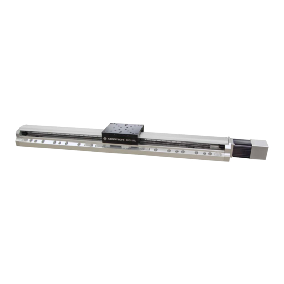
Summary of Contents for Aerotech ECO115SL Series
-
Page 1: Eco115Sl Hardware Manual
ECO115SL Hardware Manual Revision: 1.02.00... - Page 2 This manual contains proprietary information and may not be reproduced, disclosed, or used in whole or in part without the express written permission of Aerotech, Inc. Product names mentioned herein are used for identification purposes only and may be trademarks of their respective companies.
-
Page 3: Table Of Contents
3.4. Limits, Marker, and Machine Direction 3.5. Motor and Feedback Phasing Chapter 4: Maintenance 4.1. Service and Inspection Schedule 4.2. Cleaning and Lubrication 4.3. Belt Adjustment 4.4. Troubleshooting Appendix A: Warranty and Field Service Appendix B: Revision History Index www.aerotech.com... -
Page 4: List Of Figures
Analog Encoder Phasing Reference Diagram Figure 3-6: Encoder Phasing Reference Diagram (Standard) Figure 4-1: Hardcover Screw Removal Figure 4-2: Hardcover Removal Figure 4-3: Foldback Motor Cover Removal Figure 4-4: Foldback Motor Part Callouts Figure 4-5: Lubricate the Pulley Flanges www.aerotech.com... -
Page 5: List Of Tables
List of Tables Table 1-1: Model Numbers and Ordering Options Table 1-2: Environmental Specifications Table 1-3: ECO115SL Series Specifications (-050 to -250) Table 1-4: ECO115SL Series Specifications (-300 to -600) Table 2-1: Stage Mounting Surface Flatness Requirement Table 2-2: Stage to Mounting Surface Hardware... -
Page 6: Safety Procedures And Warnings
N O T E : Aerotech continually improves its product offerings; listed options may be superseded at any time. All drawings and illustrations are for reference only and were complete and accurate as of this manual’s release. -
Page 7: Eu Declaration Of Incorporation
ECO115SL Hardware Manual Table of Contents EU Declaration of Incorporation Manufacturer: Aerotech, Inc. 101 Zeta Drive Pittsburgh, PA 15238-2811 herewith declares that the product: ECO115SL Linear Stage is intended to be incorporated into machinery to constitute machinery covered by the Directive 2006/42/EC as amended;... - Page 8 Table of Contents ECO115SL Hardware Manual This page intentionally left blank. www.aerotech.com...
-
Page 9: Chapter 1: Overview
Foldback Kit with Brake for .375 Inch Diameter Shaft NEMA 23 Motor Motor Orientation (Optional) Bottom cable exit (optional orientation) Left side cable exit (standard orientation) Top cable exit (optional orientation) Right side cable exit (optional orientation) Right side foldback (standard orientation) Left side foldback (optional orientation) www.aerotech.com Chapter 1... - Page 10 XZ or YZ assembly with L-bracket; 5 arc second orthogonality; alignment to within 5 ALIGN-PA5Z µm orthogonality for short travel stages Right angle L-bracket for 50 mm, 100 mm, and 150 mm travels only; HDZ115 NOTE: Requires a tabletop when mounting to an ECO series stage Chapter 1 www.aerotech.com...
-
Page 11: Environmental Specifications
1.2. Accuracy and Temperature Effects The accuracy specification of ECO115SL series stages is measured 25 mm above the table with the stage in an unloaded condition. The stage is assumed to be fully supported by a mounting surface meeting or exceeding the specification in Section 2.3. -
Page 12: Basic Specifications
Resolution is dependent on pitch, encoder resolution, and controller interpolation. N O T E : Aerotech continually improves its product offerings; listed options may be superseded at any time. All drawings and illustrations are for reference only and were complete and accurate as of this manual’s release. -
Page 13: Table 1-4: Eco115Sl Series Specifications (-300 To -600)
1. Certified with -PL1 / -PL2 option. 2. Achieved with Aerotech rotary motor with amplified sine encoder. 3. Achieved with Aerotech rotary motor with 2500 counts/rev digital encoder. 4. Requires the selection of an appropriate amplifier with sufficient voltage and current. -
Page 14: Vacuum Operation
Overview ECO115SL Hardware Manual 1.4. Vacuum Operation Aerotech can specially prepare the ECO115SL for operation in vacuum environments. Aerotech offers two vacuum preparation options; one for low vacuum (for use in atmospheric pressures to 10 torr) and one for high vacuum (preparation for environments from 10 to 10 torr). -
Page 15: Chapter 2: Installation
Allowing it to stabilize to room temperature will ensure that all of the alignments, preloads, and tolerances are the same as they were when tested at Aerotech. Use compressed nitrogen or clean, dry, oil-less air to remove any dust or debris that has collected during shipping. -
Page 16: Dimensions
Mechanical Specifications and Installation ECO115SL Hardware Manual 2.2. Dimensions Figure 2-1: ECO115SL Dimensions Chapter 2 www.aerotech.com... -
Page 17: Figure 2-2: Eco115Sl Accessory Tabletop Dimensions (-Tt3 Option)
ECO115SL Hardware Manual Mechanical Specifications and Installation Figure 2-2: ECO115SL Accessory Tabletop Dimensions (-TT3 Option) www.aerotech.com Chapter 2... -
Page 18: Figure 2-3: Eco115Sl Z-Axis Bracket Dimensions
Mechanical Specifications and Installation ECO115SL Hardware Manual Figure 2-3: ECO115SL Z-Axis Bracket Dimensions Chapter 2 www.aerotech.com... -
Page 19: Securing The Stage To The Mounting Surface
Section 2.2. for specific model mounting locations and dimensions. Table 2-2: Stage to Mounting Surface Hardware Typical Screw Mounting Hardware Torque M6 x 18 mm (or 1/4" x 3/4") SHCS with flat washers 7 N·m [5 ft·lb] www.aerotech.com Chapter 2... -
Page 20: Attaching The Payload To The Stage
N O T E : If your ECO115SL was purchased with Aerotech controls, it might have been tuned with a representative payload based on the information provided at the time of order. If the ECO115SL is started up without a payload, the servo gains provided by Aerotech with the shipment may not be appropriate and servo instability can occur. -
Page 21: Figure 2-4: Cantilevered Load Capability
ECO115SL Hardware Manual Mechanical Specifications and Installation Figure 2-4: Cantilevered Load Capability www.aerotech.com Chapter 2... -
Page 22: Figure 2-5: Stage Orientations
Mechanical Specifications and Installation ECO115SL Hardware Manual Figure 2-5: Stage Orientations The approximate amount of torque required to turn the ball screw of ECO115SL series stages can be found from Figure 2-7 or the following equation: (AxialLoad) (LeadofScrew) Torque π... -
Page 23: Figure 2-7: Torque Required To Turn Ball Screw In Vertical Orientation
ECO115SL Hardware Manual Mechanical Specifications and Installation Figure 2-7: Torque Required to Turn Ball Screw in Vertical Orientation www.aerotech.com Chapter 2... - Page 24 Mechanical Specifications and Installation ECO115SL Hardware Manual This page intentionally left blank. Chapter 2 www.aerotech.com...
-
Page 25: Chapter 3: Electrical Installation
Electrical installation requirements will vary depending on product options. Installation instructions in this section are for ECO115SL stages equipped with standard Aerotech motors intended for use with an Aerotech motion control system. Contact Aerotech for further information regarding products that are otherwise configured. -
Page 26: Motor And Feedback Connectors
N O T E : Refer to the other documentation accompanying your Aerotech equipment. Call your Aerotech representative if there are any questions on system configuration. N O T E : If using standard Aerotech motors and cables, motor and encoder connection adjustments are not required. -
Page 27: Table 3-1: Brushless Motor Connector Pinout [-M1 Through -M8]
Reserved Reserved Reserved Reserved Reserved Frame Ground (motor protective ground) Table 3-2: Mating Connector Part Numbers for the Brushless Motor Connector Mating Connector Aerotech P/N Third Party P/N Backshell ECK00656 Amphenol #17E-1726-2 Sockets [QTY. 4] ECK00659 ITT Cannon #DM53744-6 Connector... -
Page 28: Table 3-5: Brushless Motor Feedback Connector Pinout [-M1 Through -M8]
Reserved Brake + 1. BMS motors only (otherwise Reserved) 2. With -BK (Brake) option only Table 3-6: Mating Connector Part Numbers for the Brushless Motor Feedback Connector Mating Connector Aerotech P/N Third Party P/N Backshell ECK00656 Amphenol #17E-1726-2 Connector ECK00300 FCI DB25S064TLF Chapter 3 www.aerotech.com... -
Page 29: Table 3-7: Stepper Motor Feedback Connector Pinout [-M9 And -M10]
Sine-N Reserved Common ground Common ground Reserved Reserved Reserved Reserved Table 3-8: Mating Connector Part Numbers for the Stepper Motor Feedback Connector Mating Connector Aerotech P/N Third Party P/N Backshell ECK00656 Amphenol #17E-1726-2 Connector ECK00300 FCI DB25S064TLF www.aerotech.com Chapter 3... -
Page 30: Table 3-9: Limit Connector Wiring [-Li1 And -Li2]
Signal indicating stage maximum travel produced by negative/CCW stage direction Reserved Common ground Reserved Reserved Table 3-10: Mating Connector Part Numbers for the Limit Connector Mating Connector Aerotech P/N Third Party P/N 9-Pin D-Connector ECK00340 FCI DE09S064TLF Backshell ECK01021 Amphenol 17E-1724-2 Chapter 3... -
Page 31: Motor And Feedback Wiring
ECO115SL Hardware Manual Electrical Specifications and Installation 3.2. Motor and Feedback Wiring Shielded cables are required for the motor and feedback connections. Figure 3-1: Brushless Motor and Feedback Wiring [-M1 through -M8] www.aerotech.com Chapter 3... -
Page 32: Figure 3-2: Stepper Motor And Feedback Wiring [-M9 And -M10]
Electrical Specifications and Installation ECO115SL Hardware Manual Figure 3-2: Stepper Motor and Feedback Wiring [-M9 and -M10] Chapter 3 www.aerotech.com... -
Page 33: Motor And Feedback Specifications
Note: If the ECO115SL is driven beyond the electrical limit, it will encounter a mechanical stop. Impacting the mechanical stop could cause damage to the stage even at low speeds. Brake Specifications Supply Voltage 24 VDC Supply Current (typical) 250 mA (Current required to release the brake and allow motion.) www.aerotech.com Chapter 3... -
Page 34: Table 3-12: Eco115Sl Motor Specifications (Bms60)
Electrical Specifications and Installation ECO115SL Hardware Manual N O T E : Aerotech continually improves its product offerings; listed options may be superseded at any time. All drawings and illustrations are for reference only and were complete and accurate as of this manual’s release. -
Page 35: Table 3-13: Eco115Sl Motor Specifications (Bm75)
5. Torque constant and motor constant specified at stall 6. Maximum winding temperature is 130 °C 7. Ambient operating temperature range 0 °C - 25 °C; consult Aerotech for performance in elevated ambient temperatures 8. All Aerotech amplifiers are rated A ;... -
Page 36: Table 3-14: Eco115Sl Motor Specifications (Sm60-Vt2)
-M3, -M4, -M7, -M8 with 1000x Interpolation 5 µm 5 nm (1000 line 1Vpp Amplified Sine signal) -M3, -M4, -M7, -M8 with 4000x Interpolation 5 µm 1.25 nm (1000 line 1Vpp Amplified Sine signal) 1. Quadrature decoding included in interpolated resolution calculations Chapter 3 www.aerotech.com... -
Page 37: Limits, Marker, And Machine Direction
Electrical Specifications and Installation 3.4. Limits, Marker, and Machine Direction Aerotech stages are configured to have positive and negative "machine" directions. The machine direction defines the phasing of the feedback and motor signals and is dictated by the stage wiring (refer to Section 3.5. -
Page 38: Motor And Feedback Phasing
Electrical Specifications and Installation ECO115SL Hardware Manual 3.5. Motor and Feedback Phasing Motor phase voltage is measured relative to the virtual wye common point. Figure 3-4: Hall Phasing Chapter 3 www.aerotech.com... -
Page 39: Figure 3-5: Analog Encoder Phasing Reference Diagram
ECO115SL Hardware Manual Electrical Specifications and Installation Figure 3-5: Analog Encoder Phasing Reference Diagram Figure 3-6: Encoder Phasing Reference Diagram (Standard) www.aerotech.com Chapter 3... - Page 40 Electrical Specifications and Installation ECO115SL Hardware Manual This page intentionally left blank. Chapter 3 www.aerotech.com...
-
Page 41: Chapter 4: Maintenance
Re-tighten loose connectors. Replace or repair damaged cables. Clean the ECO115SL and any components and cables as needed. Repair any damage before operating the ECO115SL. Inspect and perform an operational check on all safeguards and protective devices. www.aerotech.com Chapter 4... -
Page 42: Cleaning And Lubrication
Cleaning If a solvent is necessary for cleaning the stage, Aerotech recommends using isopropyl alcohol. Harsher solvents, such as acetone, may damage the plastic and rubber seals on the ball screw and bearing trucks. - Page 43 9. Repeat steps 3 through 9 for any areas covered by the original table position. 10. Refasten the hardcover. 11. Restore power to the stage; drive the stage table back to its original position to redistribute lubricants. www.aerotech.com Chapter 4...
-
Page 44: Figure 4-1: Hardcover Screw Removal
Maintenance ECO115SL Hardware Manual Figure 4-1: Hardcover Screw Removal Chapter 4 www.aerotech.com... -
Page 45: Figure 4-2: Hardcover Removal
ECO115SL Hardware Manual Maintenance Figure 4-2: Hardcover Removal www.aerotech.com Chapter 4... -
Page 46: Belt Adjustment
11. Check the pulley flanges for lubrication. 12. Add small amounts of Parker Super O-Lube lubricant around the circumference of both pulley flanges (Figure 4-5). 13. Replace the foldback cover and mounting screws. 14. Restore power to the stage and resume normal use. Chapter 4 www.aerotech.com... -
Page 47: Figure 4-3: Foldback Motor Cover Removal
ECO115SL Hardware Manual Maintenance Figure 4-3: Foldback Motor Cover Removal www.aerotech.com Chapter 4... -
Page 48: Figure 4-4: Foldback Motor Part Callouts
N O T E : If the stage has been calibrated (-PL2 option), note the orientation of the two pulleys with regard to each other or recalibration might be required. Figure 4-4: Foldback Motor Part Callouts Figure 4-5: Lubricate the Pulley Flanges Chapter 4 www.aerotech.com... -
Page 49: Troubleshooting
Chapter 3 and Controller Stage moves uncon- documentation). trollably Motor Connections (refer to Chapter 3 and the Controller documentation). Stage oscillates or Gains misadjusted (refer to the Controller documentation). squeals Encoder signals (refer to the Controller documentation). www.aerotech.com Chapter 4... - Page 50 Maintenance ECO115SL Hardware Manual This page intentionally left blank. Chapter 4 www.aerotech.com...
-
Page 51: Appendix A: Warranty And Field Service
Aerotech makes no warranty that its products are fit for the use or purpose to which they may be put by the buyer, whether or not such use or purpose has been disclosed to Aerotech in specifications or drawings previously or subsequently provided, or whether or not Aerotech’s... - Page 52 Aerotech's approval. On-site Warranty Repair If an Aerotech product cannot be made functional by telephone assistance or by sending and having the customer install replacement parts, and cannot be returned to the Aerotech service center for repair, and if Aerotech determines the problem could be warranty-related, then the following policy applies:...
-
Page 53: Appendix B: Revision History
ECO115SL Hardware Manual Revision History Appendix B: Revision History Revision Description 1.02.00 Dimensions updated: Section 2.2. 1.01.00 Product updates 1.00.00 New Manual www.aerotech.com Appendix B... - Page 54 Revision History ECO115SL Hardware Manual This page intentionally left blank. Appendix B www.aerotech.com...
-
Page 55: Index
Cleaning securing stage cleaning solvent multiaxis combinations Dimensions NEMA23 34-35 ECO115SL part number Motor Specifications (BM75) Possible Cause Motor Specifications (BMS60) Protection Rating Electrical Installation protective ground connection EN 60204-1 EN ISO 12100 serial number www.aerotech.com Index... - Page 56 ECO115SL Hardware Manual shimming SM60-VT2 Solution Specifications stabilizing stage stage distortion stabilizing Support Symptom Technical Support Temperature Effects thermal expansion coefficient Thermistor Specifications torque Troubleshooting Unpacking and Handling the Stage vacuum vacuum guidelines Vacuum Operation Vibration Warranty and Field Service Index www.aerotech.com...
Need help?
Do you have a question about the ECO115SL Series and is the answer not in the manual?
Questions and answers