
Related Manuals for NKT Photonics Koheras ADJUSTIK HP


Summary of Contents for NKT Photonics Koheras ADJUSTIK HP
- Page 1 Koheras ADJUSTIK (HP) Low Noise Single Frequency Laser System PRODUCT GUIDE Item 800-611-01...
- Page 2 PRODUCT GUIDE This guide includes the following NKT Photonics lasers: Koheras ADJUSTIK Low Noise Single Frequency Laser System Koheras ADJUSTIK HP High Power Low Noise Single Frequency Laser System Koheras ADJUSTIK Product Guide Release 1.0 04-2021 W-10456...
-
Page 3: Guide Overview
Koheras ADJUSTIK Safety, Handling and Regulatory Information – or – Koheras ADJUSTIK HP Safety, Handling and Regulatory Information Note: The paper copy of this document is included with your laser; however, it can also be downloaded from: https://www.nktphotonics.com/lasers-fibers/support/product-manuals/... - Page 4 September 2020 – First release - the document has been rewritten and overhauled from earlier releases. March 2021 – Release 1.1 added the Koheras ADJUSTIK HP April 2021 – Release 1.0 revision rolled back to 1.0 due to internal system...
-
Page 5: Table Of Contents
CONTENTS Guide Overview ........................3 Safety ........................3 Terminology ......................3 TABLES ........................11 FIGURES ........................13 PROCEDURES ......................17 Section 1 KOHERAS ADJUSTIK (HP) DESCRIPTION 1 Laser Description .......................21 Chassis and front panel style ................21 Terminology ......................21 Features and Options ..................22 High power variants ................... - Page 6 Amplitude modulation ..................29 Operating mode ....................29 Trigger ........................30 High temperature shutdown ................30 Power verification ....................30 Optical interface......................31 Optical fibers, connectors and adapters ............31 Laser Control ......................32 User interface ...................... 32 Status LEDs ........................ 33 Chassis labels......................
- Page 7 General operation ....................49 Menu items ........................ 50 Top menu ......................50 Wavelength ......................51 Wavelength display ..................... 51 W1 modulation ...................... 51 W1 mod. Gain ....................... 52 W1 mod. source ....................52 W1 mod. Coupling ....................52 W1 mod. Range ....................53 Power /current mode ..................
- Page 8 Relocating panels ....................70 Toggling panels .....................71 Connecting to the laser ..................71 Device Selector .....................71 Status panel ....................... 72 Status indicators ....................72 System info ......................73 Measurements ......................73 WL mod button and indicator ................73 Amp mod button and indicator ................73 Emission button ....................73 CONTROL settings....................
- Page 9 Operating and storage environment ............. 89 8 Connecting the Laser ......................91 Connecting the safety interlock ................91 Simplified Interlock operation ................91 Interlock alarm ..................... 92 Acknowledging interlock alarms ..............92 Connecting an interlock switch ..............92 Bus defeater ......................93 Connecting power ....................
- Page 10 E Part numbers ........................113...
-
Page 11: Tables
Table 9: CONTROL panels and menu items ..............69 Table 10: Power specifications..................93 Table 11: Koheras ADJUSTIK optical specifications............. 99 Table 12: Koheras ADJUSTIK HP optical specifications ...........100 Table 13: Mechanical dimensions ..................100 Table 14: Operating and storage environment ............100 Table 15: Electrical.......................100... -
Page 13: Figures
FIGURES Figure 1: ADJUSTIK front panel ..................21 Figure 2: ADJUSTIK HP front panel ................. 21 Figure 3: ADJUSTIK HP front panel layout ..............27 Figure 4: ADJUSTIK rear panel layout ................28 Figure 5: Top panel label locations ................34 Figure 6: Rear panel label location ................. - Page 14 Figure 30: Watchdog timer setting ................. 54 Figure 31: Setting the intensity level of the LCD panel back light ......54 Figure 32: IP address setting .................... 55 Figure 33: GUI panel navigation ..................69 Figure 34: Panel dragged to a new location in the main window - ....... 70 Figure 35: Panels dragged outside the main window ..........
- Page 15 Figure 63: Lint-free wipe example .................. 96 Figure 64: Example of a fiber cleaning cartridge ............96 Figure 65: Warranty seal ....................103 white...
-
Page 17: Procedures
PROCEDURES Procedure 1: Connecting a PC to the laser using a USB cable ....... 57 Procedure 2: Connecting a PC to the laser using Ethernet ........59 Procedure 3: Turning on the laser using CONTROL..........63 Procedure 4: Turning on the laser using the front panel controls ......65 Procedure 5: Relocating panels .................. -
Page 19: Koheras Adjustik (Hp) Description
SECTION 1 KOHERAS ADJUSTIK (HP) DESCRIPTION This section provides a description of the following topics: “Laser Description” on page 21 • “Module variants” on page 24 • “Laser features” on page 28 • “Miscellaneous” on page 30 • “Optical interface” on page 31 •... -
Page 21: Laser Description
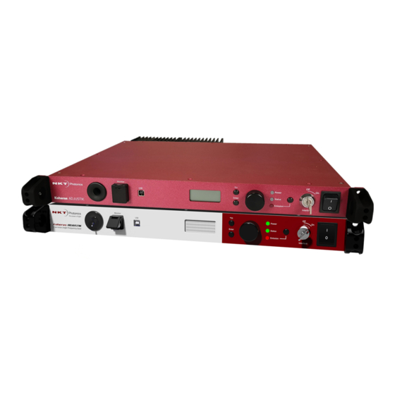
Laser Description The Koheras ADJUSTIK and ADJUSTIK HP are single frequency distributed feedback (DFB) fiber lasers with passive vibration reduction. The systems are housed within a rack mount control chassis which includes a front panel operational interface. Their optical output is defined by an ultra-narrow line width in the Hertz range and exceptionally low frequency and intensity noise. -
Page 22: Features And Options
Features and The laser series includes the following features and options: Options Thermal Tuning – varies the wavelength using coarse thermal control of the • laser substrate. Piezo Tuning – achieves fast wavelength modulation with finer control. • Polarization-maintaining (PM) fiber – To maintain polarization, the optical •... -
Page 23: Theory Of Operation
Koheras ADJUSTIK Safety, Handling and Regulatory Information – or – Koheras ADJUSTIK HP Safety, Handling and Regulatory Information A paper copy of this document is included with your laser. If you do not have access it, you can download a copy from:... -
Page 24: Module Variants
For ADJUSTIK HP lasers, the output power is variable from 10-100% of its maximum power output. Support contact details on Contact NKT Photonics support for more information - see page 104. -
Page 25: Tuning Types
Module variants Tuning types The laser’s variants can be further specified with different tuning options. The options include narrow and wide thermal tuning for coarse adjustment, Piezo tuning for finer adjustment and output power tuning. The tuning options must be specified when the laser is ordered from the factory. -
Page 26: Front And Rear Panels
Front and rear panels Front and rear panels Front panel shows the front panel of the laser. On the front panel are two optical Figure 3 outputs, main and monitor. The front panel also includes controls to turn on and operate the laser autonomously without using a CONTROL PC. -
Page 27: Rear Panel
Front and rear panels Figure 3 ADJUSTIK HP front panel layout Optical output (main fiber output) Keyswitch Monitor optical output Rack mounting flange and finger-grip USB serial connector Menu button LCD display panel 10 Selection dial Menu return button Emission button Status LEDs 12 AC mains switch Rack mounting... -
Page 28: Optical Specifications
Optical specifications always be placed on the External bus connector to loop back the interlock safety circuit – see “Connecting the safety interlock” on page Figure 4 ADJUSTIK rear panel layout AC mains inlet 10/100 BASE-T Ethernet port LEMO door interlock connector External bus Modulation (input and output) Cooling fins... -
Page 29: External Cavity Stabilization
Laser features Input circuits Section provides examples of fast “Fast wavelength modulation” on page 37 wavelength modulation circuits and performance. Wavelength+/- Signal To modulate the laser’s wavelength, you can apply an external differential signal to the modulation connector pins on the rear panel. As the input signal varies and increases its positive potential, the wavelength of the laser increases. -
Page 30: Trigger
Laser features Power mode – the power out of the fiber laser is held at a fixed level. • The mode set, depends on both the variant and the application. lists the Table 2 characteristics of the modes for each of the laser variants. Table 2 Characteristics of power modes ADJUSTIK Power mode... -
Page 31: Optical Interface
Fiber Mode Field Diameter Numerical Aperture 0.14 0.12 0.125 Mode field diameter is approximate - contact NKT Photonics Support for more Support contact details on page 104 information – see Example specifications listed are design intent and are subject to change. Support... -
Page 32: Laser Control
User interface The laser and any associated accessories are controlled using either from a PC using NKT Photonics CONTROL management software or the front panel interface. As an option, the laser can also be controlled using NKTP’s Software Development Kit (SDK) for custom applications. For further information regarding the SDK refer to the software and drivers link at NKTP’s support webpage:... -
Page 33: Status Leds
Note: the laser until you are familiar with the controls and have taken O NOT OPERATE all precautions necessary as described in the document: Koheras ADJUSTIK Safety, Handling and Regulatory Information or Koheras ADJUSTIK HP Safety, Handling and Regulatory Information. -
Page 34: Chassis Labels
Chassis labels Chassis labels The laser chassis has a number of labels on it that indicate hazards, regulatory, or manufacturing information. The labels are located on the panels described in Table 5 with the panels shown in Figure 5 Figure Figure 5 Top panel label locations Figure 6 Rear panel label location... -
Page 35: Table 5 Module Labels
Chassis labels Table 5 Module labels Label Panel Description Classification - Safety information stating the laser Emission emission hazards and the laser’s class Hazards rating. WARNING- INVISIBLE LASER RADIATION AVOID EXPOSURE TO BEAM Koheras CLASS 3B LASER PRODUCT ADJUSTIK Classification - Safety information stating the laser Emission emission hazards and the laser’s class... - Page 36 Chassis labels...
-
Page 37: Modulation
Modulation This section presents further information on how to implement: Wavelength modulation (fast) – “Fast wavelength modulation” on page 37 • Amplitude modulation – “Amplitude modulation” on page 44 • External cavity stabilization – “External cavity stabilization” on page 46 •... -
Page 38: Wavelength+/- Signal
Fast wavelength modulation Table 6 Wavelength modulation settings Setting Function For CONTROL see For SDK see External wavelength Sets wavelength page 74 page 84 modulation modulation to external signal mode. Internal function Sets wavelength page 75 page 84 generator modulation to internal function generator mode. -
Page 39: Differential Input
Fast wavelength modulation Differential input When configured as an input, the Wavelength+/- interface can be connected to a differential signal with an amplitude up to 2x 5 Vpp as shown in Figure Figure 7 Differential input signal for wavelength modulation Note: To prevent noise being induced that could create undesired phase noise, it is recommended to disable the wavelength modulation setting when it is not in... -
Page 40: Figure 9: Single-Ended Input Signal With 2.5 V
Fast wavelength modulation 2.5 V or AGND. A single-ended 5 Vpp signal generates half the modulation compared to a differential 2x5 Vpp input. Figure 9 Single-ended input signal with 2.5 V shows the Wavelength- pin connected to the same potential as the Figure 10 common mode voltage of the Wavelength+ signal, the optical output will be modulated around its center wavelength. -
Page 41: Wavelength- To Agnd
Fast wavelength modulation Wavelength- to 12, the Wavelength- signal is connected to AGND and the Wavelength+ Figure AGND signal is modulated between 0 and 5 V as shown in 11, the optical output Figure is modulated above its thermally controlled wavelength. Figure 11 Single-ended input signal with GND on an unused branch Figure 12 Single-ended input connections with 0 V on an unused branch... -
Page 42: Differential Output
Fast wavelength modulation Differential output If the Wavelength+/- pins are configured as an output, a differential signal will be present at the pins as shown in 13. The differential signal amplitude can Figure be up to 2x 5 Vpp with a common mode voltage of 2.5 V. Figure 13 Differential output signal The differential output signal can be used for example, as the input signal for other Koheras ADJUSTIK or ADJUSTIK HP lasers. -
Page 43: Frequency Response
Fast wavelength modulation Frequency For X15 variants, the frequency response of the wavelength modulation feature response differs from that of the E15/C15/Y10 variants. The graphs in (X15) and Figure 14 (E15/C15/Y10) shows the response when the modulation signal varies Figure 15 from 1 to 100 kHz. -
Page 44: Amplitude Modulation
Amplitude modulation Narrow – 10x (times) less with a 3 dB cut-off at 1 kHz • Figure 15 E15/C15/Y10 variant wavelength modulation response Amplitude modulation If the laser includes the amplitude modulation option, the output emission power level can be modulated. The power amplitude can be modulated with either an electrical input signal or the built-in function generator. -
Page 45: Figure 16 Differential Input For Amplitude Modulation
Amplitude modulation when the summation exceeds 0V and reaches its maximum (the power setpoint) +5 V separation. Figure 16 Differential input for amplitude modulation Alternatively, shows the Amplitude+/- negative pin connected to Figure 17 • ground with the positive branch connected to a signal that varies between 0 V and +5 V. -
Page 46: External Cavity Stabilization
External cavity stabilization External cavity stabilization The lasers can be locked to an external cavity to obtain lower low-frequency phase noise by using the Pound-Drever-Hall technique. depicts a Figure 18 general layout of the devices in a Pound-Drever-Hall configuration used with the laser. -
Page 47: Operating The Laser
SECTION 2 OPERATING THE LASER This section describes how to manage and operate the laser and includes the chapters: “Front Panel Menu” on page 49 • “Communicating with the Laser” on page 57 • “Turning ON the Laser” on page 61 •... -
Page 49: Front Panel Menu
Front Panel Menu Overview The front panel features an LCD system menu and controls that can be used to configure and operate the laser. The menu items available are listed in Table Table 8 Front panel menu items Menu Item Function Top menu Displays the wavelength, output power and... -
Page 50: Menu Items
Menu items Navigate to sub-menu’s from the top level. • Adjust parameter values when they are selected using the enter button. • Emission button - see “Emission button” on page 55 Press this button to: Enable laser emission. • Disable laser emission. •... -
Page 51: Wavelength
Menu items Wavelength Enter the Wavelength menu (Figure 20) to change the center wavelength of the laser emission. You can specify it as an absolute wavelength or specify a relative offset from the nominal wavelength. Figure 20 Wavelength setting menu Wavelength display The Wavelength display menu (Figure... -
Page 52: W1 Mod. Gain
Menu items W1 mod. Gain Use the W1 mod. Gain menu to adjust the gain of the signal used to modulate the wavelength. Enter the menu and adjust the gain from 0 to 242.5%. Figure 23 Wavelength modulation gain setting menu W1 mod. -
Page 53: W1 Mod. Range
Menu items W1 mod. Range In the W1 mod. Range menu (Figure 26), you can set the depth of the modulation range to either Narrow or Wide. Refer to “Narrow vs. Wide modulation range” on page 42 for more information on how to set the range. Figure 26 Wavelength modulation range set to Narrow Power /current The Power/current mode menu... -
Page 54: Power Unit
Menu items Power unit Power can be set and displayed in either milliwatts (mW) or decibel-milliwatts (dBm). Select this menu item and turn the selection dial left or right to set the power units to either mW or dBm. Figure 29 Power unit menu - set to mW Watchdog timer If the communications link between the laser and the CONTROL GUI on a PC is lost, you can enable the watchdog timer to disable emission. -
Page 55: Ip Address
Ensure to observe and implement all safety regulations, warnings and cau- tions in this guide and in either the Koheras ADJUSTIK Safety, Handling and Regulatory Information or Koheras ADJUSTIK HP Safety, Handling and Regulato- ry Information document before continuing. - Page 56 Menu items...
-
Page 57: Communicating With The Laser
CONTROL communications to the laser using either an USB or Ethernet connection. CONTROL software The laser is shipped with the NKT Photonics CONTROL software installer on a USB key. You can also download the most recent CONTROL software from the following link: https://www.nktphotonics.com/lasers-fibers/support/software-drivers/... -
Page 58: Ethernet Connection
Connecting the laser to a CONTROL PC Action Launch the CONTROL software by either: • clicking on Windows – Start – Programs – NKT Photonics –CONTROL – or – • double clicking the CONTROL shortcut on the desktop The CONTROL window opens. -
Page 59: Procedure 2 Connecting A Pc To The Laser Using Ethernet
Connecting the laser to a CONTROL PC Procedure 2 Connecting a PC to the laser using Ethernet Action Configure the ADJUSTIK IP address using either CONTROL connected over USB (Ethernet on page 78 or the front panel controls (IP Address on page 55). - Page 60 Connecting the laser to a CONTROL PC Action To delete or modify a configured port: Delete button 1 Highlight the port and Click the delete button - or - 2 Click the edit button 3 Click Save when finished. Edit button Using a CAT5 or better Ethernet cable, connect the laser’s Ethernet port either directly to a CONTROL PC Ethernet port or to a subnet accessible by the PC.
-
Page 61: Turning On The Laser
Koheras ADJUSTIK Safety, Handling and Regulatory Information – or – Koheras ADJUSTIK HP Safety, Handling and Regulatory Information You must follow all safety regulations required at the location where the laser will be operated. Preparation The laser is ready to be turned on when the following steps are completed. -
Page 62: Back Reflection
Enabling and disabling emission Caution: Do not turn on the laser if it has been exposed to temperature and hu- midity beyond the operating specifications. The laser is designed to operate in a non-condensing environment from +15°C to +60°C. Before turning on the laser, al- low it at least 30 minutes to stabilize at the operating room temperature. -
Page 63: Procedure 3 Turning On The Laser Using Control
Enabling and disabling emission Procedure 3 Turning on the laser using CONTROL Action 1 Connect to the laser using the procedures in Communicating with the Laser on page 2 If the indicator for Interlock in the status panel is RED and Status is AMBER, check the following: a. -
Page 64: Enable Emission (Front Panel)
Enabling and disabling emission Action 5 Observe that the status panel is shown with indicators in the emission enabled state. Status indicators lit GREEN and Emission Enabled lit RED 6 a. Set the reference wavelength offset for the λ module using the slider in the Wavelength λ... -
Page 65: Procedure 4 Turning On The Laser Using The Front Panel Controls
Enabling and disabling emission Procedure 4 Turning on the laser using the front panel controls Action 1 Connect to the laser using the procedures in Communicating with the Laser on page 2 a. If the interlock circuit is in an open state or not terminated with the included External bus defeater –... - Page 66 Enabling and disabling emission Action 5 The Laser off message indicates laser emission can be enabled. To enable emission, press the emission button on the front panel – see Figure Laser is ready to enable emission 6 Emission ENABLED message – the emission wavelength and power level is displayed.
- Page 67 Enabling and disabling emission Action 8 a. Adjust wavelength – Press the enter button and using the selection dial, select the Wavelength setting menu. Once selected, use the selection dial and enter button to adjust the wavelength (λ). Wavelength and b.
- Page 68 Enabling and disabling emission...
-
Page 69: Using Control
Using CONTROL CONTROL overview The CONTROL interface includes multiple panels and a selection of menu drop down items in the upper left corner. Using the Window drop down menu, you can add or remove the displayed panels and panels can be dragged within the main window or into separate windows. -
Page 70: Relocating Panels
CONTROL overview Relocating panels The window panels displayed by CONTROL can be dragged to other positions within the main interface or into a separate floating panel. Procedure 5 describes how to move a panel: Procedure 5 Relocating panels Action Left click hold the top title bar of a panel. While holding the left mouse button down, drag the panel to another position in the main window. -
Page 71: Toggling Panels
CONTROL overview Toggling panels Use the Menu > Window drop down menu to check and uncheck panels to be displayed. A blue check mark indicates the panel is displayed. Figure 36 Panels dragged outside the main window Check the panels to display them Note: Clicking the ‘X’... -
Page 72: Status Panel
Status panel Status panel The Status Panel provides status indicators, error messages, emission control function and a settings drop down menu. Figure 39 Status panel Click Status indicators The panel includes the following indicators: Interlock Indicates the status of the interlock circuit. ON Green –... -
Page 73: System Info
Status panel ON Amber – The laser is in the process of warming up or an error is detected. • System info The System Info section shows the following: Laser serial number • Laser firmware version • Measurements Displays the system temperature. WL mod button and Button indicator... -
Page 74: Control Settings
CONTROL settings CONTROL settings The GUI settings are accessible by clicking the gear icon in the upper right corner of the Status panel. Clicking the gear icon, drops down a menu of setting items as shown in Figure Figure 40 GUI settings Click the gear icon to access the menu Function... -
Page 75: Figure 41 Wavelength Modulation - Internal Source
CONTROL settings You can connect an external signal to either the laser’s interface board connectors as described in “Connecting modulation signals” on page 94 directly to the main electrical interface pins. The pin assignments are described Table 18 on page 105. - Page 76 CONTROL settings coupling. Refer to “Wavelength modulation coupling” on page 42 for further information. Note: When using wavelength modulation with an X15 laser, and the Modulation range parameter is set to Narrow, the modulation signal will be AC-coupled, and the DC-component enters a software integrating function that tunes the wave- length up or down when the DC-voltage varies either positive or negative re- spectively.
-
Page 77: Amplitude Modulation
CONTROL settings Narrow and Wide modulation gain You can use this slider to increase the gain of an external modulation signal input applied to the Wavelength+/- pins. Increasing the gain will directly increase the wavelength modulation achievable with the signal. Internal generator power Level You can set the output power level of the internal function generator to between 0 and 100%. -
Page 78: Ethernet
CONTROL settings Internal amplitude modulation To modulate the output power using an internal generator, set the amplitude modulation source to internal. Figure 46 shows the Internal generator settings. Figure 46 Internal amplitude modulation settings Type – Select the modulation waveform type: Sinusoidal, Triangle, Sawtooth, or Inverse Sawtooth. -
Page 79: Watchdog
CONTROL settings the same port for transmission as for reception (i.e. as configured under the System port). Default setting is 0. If Local port in CONTROL’s Ethernet connection is configured different than the Remote port, the computer’s port should match the Remote port. -
Page 80: Clock
CONTROL settings Figure 48 Watchdog setting Enables the Watchdog Clock Within the Clock setting menu, the system date and time can be automatically read or set by updating the settings from a connected PC. Date Displays the system date in the format DD/MM/YYYY. Time Displays the system time in 24 hour format: HH:MM:SS. -
Page 81: View
CONTROL menu items View Check the System info box to display the laser serial number, firmware release number or system temperature within the status panel. You can also input the name of your system in the User text input field. The text is displayed next to the laser’s icon in the Device Selector panel. -
Page 82: Serial Monitor
Serial monitor Serial monitor You can view the real time RS-232 serial communication messaging to and from the laser using the Serial monitor panel. The panel can be used for: Debugging communication with the laser. • Issuing CLI commands to the laser using the command input field. •... -
Page 83: Control - Control Panel
CONTROL – Control panel CONTROL – Control panel The control panel for the laser can be configured to present different operating mode controls for either Power or Current mode. The modes are selected by clicking on the Settings drop down menu (gear icon) in the status panel. See “CONTROL settings”... - Page 84 CONTROL – Control panel...
-
Page 85: Installing The Laser
SECTION 3 INSTALLING THE LASER This section provides information on how to install the laser and includes the chapters: “Mechanical Installation” on page 87 • “Connecting the Laser” on page 91 •... -
Page 87: Mechanical Installation
Mechanical Installation The laser chassis is designed to be installed on a flat surface or rack-mounted in a standard 19-inch rack. This section describes how to mount the laser module to ensure optimal function and ensure that heat generated by the laser, is adequately dissipated. -
Page 88: Rack Mounting The Laser
Rack mounting the laser Rack mounting the laser The laser can be mounted in a standard 19-inch rack using rack mounting screws and cage nuts. shows the laser’s flange on the right side being affixed Figure 56 to a standard rack. Use the finger grips on the flange to help balance the laser when you are mounting it in a rack. -
Page 89: Operating And Storage Environment
Placing the laser on a table or shelf Figure 57 Rubber mounting feet Rubber feet Figure 58 Table or shelf mounting Operating and details the required ambient operating and storage environment Appendix A storage specifications. environment Warning: A Koheras ADJUSTIK laser is either a Class 3B or Class 4 laser prod- uct, and its operation facility and conditions must comply with the standards list- ed below or similar:... - Page 90 Placing the laser on a table or shelf...
-
Page 91: Connecting The Laser
Connecting the Laser Before operating the laser, follow the procedures in this chapter to ensure its correct and safe operation. For information on how to connect: The safety interlock – see “Connecting the safety interlock” on page 91 • Power – see “Connecting power”... -
Page 92: Interlock Alarm
Caution: Do not short-circuit the Interlock input. Short-circuiting the interlock cir- cumvents safety regulations and NKT Photonics does not take liability for any in- juries or damage caused by doing so. Caution: The switch connected to the interlock must be of an approved type. -
Page 93: Bus Defeater
Connecting power Procedure 6 Connecting the door interlock circuit Action Install a switch that opens when the door accessing the laser installation enclosure is opened. The switch must comply with safety regulations. Using a cable with a maximum wire length of five meters and at a minimum 26 AWG, connect the switch to a LEMO connector. -
Page 94: Connecting Modulation Signals
Connecting modulation signals Connecting modulation signals Input and output wavelength modulation signals are described in chapter 2: “Modulation”. Input modulation signals are connected to the DB-9 pin connector on th rear panel, see “Modulation input/output” on page 105. Connecting the trigger input or output The laser includes a trigger logic input/output signal as part of the Modulation connector (see 18). -
Page 95: Connecting The Optical Output
Using the microscope, check for any de- formities, damage, residue or other contaminants at the optical tip of the connec- tor. Either clean the connector or contact NKT Photonics support if a replacement is necessary. -
Page 96: Cleaning Of Fiber Facets
Cleaning of fiber facets Before using the laser, inspect the fiber and it’s facets for damage and • contaminants - if they need cleaning see “Cleaning of fiber facets” on page Cleaning of fiber facets The facets of the system fiber connectors may occasionally require cleaning. Particularly for ADJUSTIK HP variants, as any contaminants might be susceptible to the system’s higher output power. -
Page 97: Appendices
APPENDICES The appendices include: Specifications Appendix A on page 99 • Service and Support Appendix B on page 103 • Interface Pin Assignments Appendix C on page 105 • CONTROL Installation Appendix D on page 107 • Configuration ID cross-reference Appendix E on page 113 •... -
Page 99: A Specifications
Specifications Table 11 Koheras ADJUSTIK optical specifications CW - inherently single frequency Laser Emission > 10 > 10 Output power (mW) < 1.05 < 1.05 < 1.05 < 1.05 Beam Quality (M2) < 0.1 < 0.1 < 15 < 20 Linewidth (kHz) -110 @ 1 Hz Max. -
Page 100: Table 12 Koheras Adjustik Hp Optical Specifications
Table 12 Koheras ADJUSTIK HP optical specifications CW - inherently single frequency Laser Emission 0.2 / 2.0 0.2 / 2.0 0.2 / 2.0 Output power (W) 1545-1565 1545-1565 1545-1565 1060-1075 Operating wavelength 10-100 10-100 10-100 10-100 Output power tuneability (%) <... -
Page 101: Table 16 Safety And Regulatory Compliances
Table 16 Safety and regulatory compliances Safety Regulatory EN 60825-1:2014: Safety of laser products EN 61326-1:2013: Electrical equipment for measurement, Part 1: Equipment classification and requirements control and laboratory use EMC requirements – Part 1: General requirements [Laser Class 4] 2004/108/EC Electromagnetic Compatibility EN 61010-1:2010:Safety requirements for electrical 2011/65/EC Restriction of the use of certain Hazardous... -
Page 103: B Service And Support Information
Service and support Information Servicing the laser The laser have no user serviceable components. In case of malfunction, contact NKT Photonics using the support channels in section “Support contact details”. Caution: Do not open the laser’s modules. The laser modules are equipped with warranty labels (see 65) on the covers of the laser chassis. -
Page 104: Support Contact Details
Support contact details Support contact details If you need help or have questions regarding your Koheras ADJUSTIK laser or its accessories, contact NKT Photonics through our support website below: Support website 1. Go to: https://www.nktphotonics.com/lasers-fibers/support/technical-support-and- customer-service/ 2. Scroll down and click or press: 3. -
Page 105: C Interface Pin Assignments
Interface Pin Assignments Modulation input/output The Modulation input/output interface on the laser is a 9 pin male DB-9 connector. The pin assignments are described in Table Table 18 Modulation connector pin assignment Pin # Signal Description Trigger Logic input/output for either control or indication of laser emission. Active high. - Page 106 External bus Pin # Signal Description Interlock Logic Outputs a logic high (5V) when the interlock circuit is closed and has Output been reset. This signal can be used to control safety related precautions on the External Bus. 5,6,13,14 0 volt ground. 7,8,15 +12 V 12 volt supply voltage for external accessories.
-
Page 107: D Control Software
CONTROL Software Installing CONTROL Download the software from: https://www.nktphotonics.com/lasers-fibers/support/software-drivers/ Follow the steps in Procedure Procedure 7 Installing CONTROL Action On the PC, launch the installer package and then click the Installer Run button. The installation wizard appears. Click Next to continue. - Page 108 Installing CONTROL Action Accept to use the default installation directory or select another directory by clicking the Browse button. Click Next to continue. Uncheck the components you do not require. By default, all components will be installed. Click Next to continue. Read the End-User License Agreement and select: “I accept the license.”.
- Page 109 Installing CONTROL Action The wizard will create a start menu folder with program short-cuts. Use the default name or enter a new name for the folder. Click Next to continue. Check the box to create a desktop shortcut to access Control.
- Page 110 Installing CONTROL Action Click Install to install NKTP Control software on your PC. Click Cancel if you want to abort the installation. The wizard displays a progress meter for the installation. Note: a normal install should only take a few seconds. Click Next to install the UART drivers for the PC USB port.
- Page 111 Installing CONTROL Action The drivers will be installed. The Silicon Labs drivers is installed successfully. Click Finish to end the installation wizard. CONTROL is now installed. Check the Run box to launch CONTROL when the Finish button is clicked. Click Finish.
- Page 112 Installing CONTROL...
-
Page 113: Table 20 Adjustik And Adjustik Hp Part Numbers
40 mW Koheras ADJUSTIK K8221 > 10 mW K8227 Koheras ADJUSTIK 22.5 mW Koheras ADJUSTIK K8220 > 10 mW Koheras ADJUSTIK HP 200 mW K82223 Koheras ADJUSTIK HP K82224 Koheras ADJUSTIK HP K82214 Koheras ADJUSTIK HP 200 mW K82213 K82274... - Page 115 Koheras ADJUSTIK Product Description Release 1.0 04-2021 W-10456...
Need help?
Do you have a question about the Koheras ADJUSTIK HP and is the answer not in the manual?
Questions and answers