
Subscribe to Our Youtube Channel
Related Manuals for NKT Photonics Koheras HARMONIK Series


Summary of Contents for NKT Photonics Koheras HARMONIK Series
- Page 1 Koheras HARMONIK Low Noise Single Frequency 2nd Harmonic Laser System PRODUCT GUIDE...
- Page 2 PRODUCT GUIDE This guide includes the following NKT Photonics products: Koheras HARMONIK Low Noise Single Frequency 2nd Harmonic Laser System Koheras HARMONIK Product Description Revision 1.0 01-2020 W-10456...
-
Page 3: Guide Overview
GUIDE OVERVIEW This product guide is intended to provide functional, operational and installation information for the Koheras HARMONIK laser systems. The guide is divided into three sections: Koheras HARMONIK Description - introduces the Koheras HARMONIK • system, its functionality, interfaces and variants. Installation –... - Page 4 — The appendices contain system specifications and service and Appendices • support information. Added information Lasers are highly dangerous devices that can cause serious injury and property and safety notices damage. This guide use the following symbols to either highlight important safety information or provide further information in relation to a specific topic.
-
Page 5: Table Of Contents
CONTENTS Guide Overview ........................3 TABLES ........................7 FIGURES ........................9 1 HARMONIK System Description ..................11 Models ........................11 Installation .......................11 Optical .......................... 12 Emission beam quality ..................12 Free-space or fiber output ................12 Control module ......................12 Front panel ......................12 Rear panel ......................13 Optical module ...................... - Page 6 Installing the system ....................22 Control module ....................23 Seed and amplifier modules ................23 Connecting the system ................... 23 3 Operations ..........................27 Safety ........................... 27 Damage prevention ....................27 General ........................27 Stability ........................27 Temperature Optimization ................28 Settings Page .......................
-
Page 7: Tables
TABLES Table 1: HARMONIK system models.................. 11 Table 2: Status LED conditions..................13 Table 3: Module labels......................18 Table 4: Optical module installation requirements ............. 23 Table 5: Mechanical dimensions ..................35 Table 6: Operating and storage environment ............. 35 Table 7: Electrical ......................... -
Page 9: Figures
FIGURES Figure 1: Control module front panel ................12 Figure 2: Control module rear panel ................13 Figure 3: Optical module front panel ................14 Figure 4: Optical module rear panel ................15 Figure 5: Optical module rear panel ................16 Figure 6: BUI Ethernet connectivity ..................17 Figure 7: Label locations ........................19 Figure 8: Optical module rear panel ................ -
Page 11: Harmonik System Description
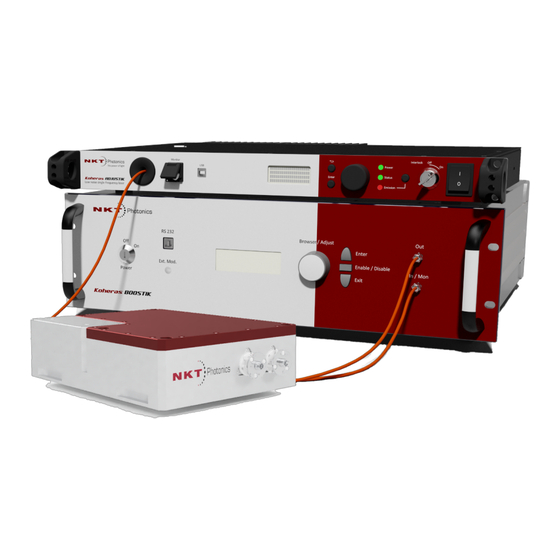
HARMONIK System Description The HARMONIK system is a high-power frequency doubled laser system. The system is modular and consists of the following modules: Optical module – the module houses the HARMONIK’s optical components • for frequency doubling the source laser beam. Specifically, this is a photonic crystal operating at 50-65°... -
Page 12: Optical
Optical Optical Emission beam The beam quality, M2 is less than 1.1 and is suitable for advanced quantum physics quality projects such as quantum sensing and laser cooling and trapping. Contact NKT Photonics to discuss the applications that are possible. Free-space or fiber By default, the HARMONIK systems are equipped with free-space output apertures. -
Page 13: Rear Panel
Control module Status LED The front panel LED indicates both when power is applied and if the second harmonic crystal oven has reached and stabilized at the set point temperature. Table 2 Status LED conditions Condition Description ON BLUE Temperature is stabilized at the setpoint ON RED Temperature has not reached or stabilized at the setpoint. -
Page 14: Optical Module
Optical module Optical module Front panel The optical module front panel houses the electrical interfaces and an optical input assembly in a cut-out along the front and right side panel as shown in Figure Figure 3 Optical module front panel Caution: DO NOT REMOVE or LOOSEN the screws marked with the Caution symbol in this image. -
Page 15: Rear Panel
Optical module Caution: Under no circumstances should the collimator assembly be disassem- bled by unscrewing the collimator clamp screws. Optical input aperture The emission from the BOOSTIK HPA is coupled through the collimator assembly to the optical input aperture from the factory aligned collimator assembly. Rear panel The rear panel houses two free-space output apertures. -
Page 16: Miscellaneous
• Note: The seed and amplifier lasers are controlled using NKT Photonics CONTROL Graphical User Interface (GUI) installed on a PC or the front panel interface. For man- aging these modules of the system refer to their respective product guides:... -
Page 17: Connectivity
CONTROL and CONFIGURATION Connectivity The Control module can connect to a PC over an IP network using Ethernet. You can connect the Ethernet port of the module either directly to a PC or to an L2 or L3 network that the PC is connected to. Figure 6 BUI Ethernet connectivity L2 or L3 Network... -
Page 18: Chassis Labels
Chassis labels Chassis labels A Koheras HARMONIK chassis has a number of labels on it that indicate hazards, regulatory, or manufacturing information. The labels are described in with the Table 3 label placements shown in Figure Table 3 Module labels Label Panel Description... -
Page 19: Figure 7 Label Locations
Chassis labels Figure 7 Label locations Rear LASER LASER APERTURE APERTURE MAXIMUM OUTPUT POWER: 15 W DANGER - INVISIBLE LASER RADIATION WAVELENGTH: 500 - 2100 nm AVOID EYE OR SKIN EXPOSURE TO EN60825-1:2014 DIRECT OR SCATTERED RADIATION CLASS 4 LASER PRODUCT Side WARRANTY VOID IF SEAL IS BROKEN OR REMOVED... - Page 20 Chassis labels...
-
Page 21: Optical And Control Module Installation
Optical and Control Module Installation General All modules types must be installed on a level surface or rack that is free from vibrations. The ambient temperature surrounding any of the optical modules should be stable and free from any sources that could cause temperature fluctuations. -
Page 22: Electrical Supply Requirements
Installing the system Electrical Supply Supply voltage is 100-240 VAC, maximum 100 W Requirements Installing the system The optical module is designed to be fastened on an optical table with M6 holes spaced apart by 25 mm. Alternatively the module can be clamped to any table using the four clamp slots available on both the left and right panels. -
Page 23: Control Module
The control module can be placed on any surface nearby the optical module such that the communications and power cable between it and the optical module is not excessively bent or stretched. Seed and amplifier Refer to the NKT Photonics documents: modules Koheras ADJUSTIK Product Guide Koheras BOOSTIK HPA Product Guide... -
Page 24: Figure 9 Removing The Optical Input Cover
ADJUSTIK laser and BOOSTIK HPA amplifier as necessary. Note: For information on Koheras ADJUSTIK and BOOSTIK HPA operations, refer to the NKT Photonics documents: Koheras ADJUSTIK Product Guide Koheras BOOSTIK HPA Product Guide 5. Remove the cover as illustrated in... -
Page 25: Figure 10 Installing The Collimator Assembly
Connecting the system Figure 10 Installing the collimator assembly Caution: DO NOT REMOVE or LOOSEN the screws marked with the Caution symbol in this image. Alignment pins 8. Replace and fasten the cover over the collimator assembly. Figure 11 Replacing the optical input cover 9. - Page 26 Connecting the system...
-
Page 27: Operations
Operations Safety Before you turn ON the Koheras HARMONIK, ensure that you are completely familiar and follow all safety information and recommendations stated within this document and the document: Koheras HARMONIK Safety, Handling and Regulatory Information You must follow all safety regulations required at the location where the system will be operated. -
Page 28: Temperature Optimization
General Temperature If the wavelength or power of the fundamental input is altered, it may be Optimization necessary to optimize the temperature setpoint to achieve the maximum second harmonic output power using the BUI controls – see “Optimizing the second harmonic output”... -
Page 29: Turning On The System
Turning on the system selected, click the Start Upgrade button and wait for the upgrade to complete and the system to reboot. Figure 13 Settings page (expanded) Turning on the system Turn on the DC power by pressing the power switch on the front panel of the Control module. -
Page 30: Setting The Ip Address
Connecting to the HARMONIK Note: The module can also be connected to either: a. a local L2 switch where the PC is also connected. b. a correctly configured IP subnet which is reachable from the PC. (Note that step 2 may not be necessary in this case.) 2. -
Page 31: Resetting The Ip Address To Default
Connecting to the HARMONIK 2. Under Connection–Address settings (see 15), either: Figure a. Check the Activate DHCP check box - this configures the HARMONIK system as a DHCP client to automatically assign it an IP address from a DHCP server. - or - b. -
Page 32: Using The System
Using the system Using the system Initial use When starting up the Koheras HARMONIK system for the first time: Set the fundamental input power from the BOOSTIK HPA amplifier to a low value i.e. P < 1 W – see document: Koheras BOOSTIK HPA Product Guide 2. -
Page 33: Auto Temperature Button
Using the system Warning: Depending on temperature setpoint optimization, almost the entire fun- damental input power is transferred to the fundamental laser output. Optimize the second harmonic emission level Turn on the system, enable emission and allow the HARMONIK crystal to warm-up until the temperature in the Temp set field stabilizes –... - Page 34 Using the system Patch cable connector cleaning Due to the high power transmitted through the single mode fiber surface of the optical connector(s), it is important to keep all connector faces extremely clean. This is particularly important for amplified systems, where the power level is high.
-
Page 35: A Specifications
Specifications Table 5 Mechanical dimensions All chassis models 48.5 x 483 x 386 mm Size (H x W x D) (1.91 x 19.02 x 15.20 in) Weight < 7 kg (< 15.4 lb) Table 6 Operating and storage environment All Chassis Models 15°... -
Page 36: Table 9 Mechanical Dimensions
Table 9 Mechanical dimensions... -
Page 37: B Service And Support Information
Service and support Information Servicing the laser The laser have no user serviceable components. In case of malfunction, contact NKT Photonics using the support channels in section “Support contact details”. “WARRANTY...” Caution: The unit is sealed with a label “WARRANTY VOID IF SEAL IS BROKEN Label OR REMOVED”. -
Page 38: Support Contact Details
Support contact details Support contact details For technical or general support, NKT Photonics can be contacted for help regarding issues and questions with your laser or its accessories. Support Email support@nktphotonics.com Online support http://www.nktphotonics.com (click on support) web-page Shipping address... - Page 39 Koheras HARMONIK Product Description Revision 1.0 02-2020 W-10456...
Need help?
Do you have a question about the Koheras HARMONIK Series and is the answer not in the manual?
Questions and answers