
Related Manuals for NKT Photonics Koheras HARMONIK


Summary of Contents for NKT Photonics Koheras HARMONIK
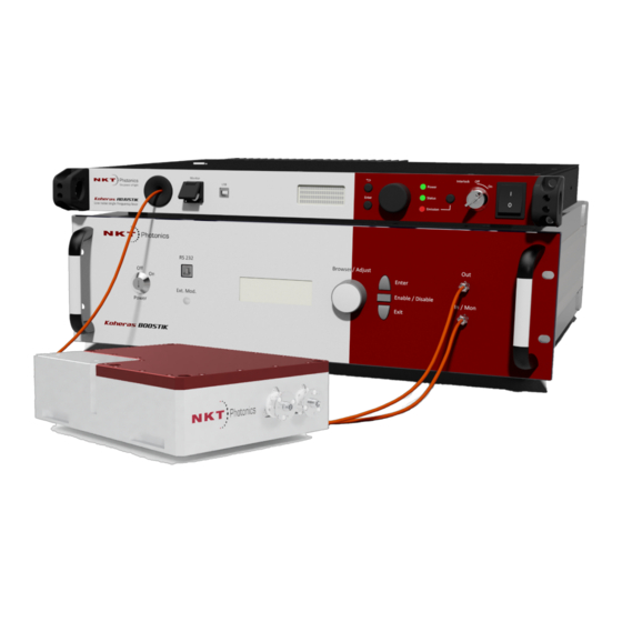
- Page 1 Koheras HARMONIK Low Noise Single Frequency 2nd Harmonic Laser System PRODUCT GUIDE Item 800-604-01...
- Page 2 PRODUCT GUIDE This guide includes the following NKT Photonics products: Koheras HARMONIK Low Noise Single Frequency 2nd Harmonic Laser System Koheras HARMONIK Product Description Release 2.1 01-2021 W-10456...
-
Page 3: Guide Overview
GUIDE OVERVIEW This product guide is intended to provide functional, operational and installation information for the Koheras HARMONIK laser systems. The guide is divided into three sections: Koheras HARMONIK Description - introduces the Koheras HARMONIK • system, its functionality, interfaces and variants. - Page 4 — The appendices contain system specifications and service and Appendices • support information. Added information Lasers are highly dangerous devices that can cause serious injury and property and safety notices damage. This guide use the following symbols to either highlight important safety information or provide further information in relation to a specific topic.
-
Page 5: Table Of Contents
CONTENTS Guide Overview ........................3 TABLES ........................7 FIGURES ........................9 PROCEDURES ......................11 1 HARMONIK System Description ..................13 Models ........................13 Installation ......................13 Optical .......................... 14 Output power and wavelengths ...............14 Emission beam quality ..................14 Free-space or fiber output .................14 Laser classification ....................14 HARMONIK module .................... - Page 6 Seed and amplifier modules ................23 Connecting the system ................... 23 3 Operations ..........................27 Safety ........................... 27 Damage prevention ....................27 General ........................27 Stability ........................27 Temperature Optimization ................28 Client software ..................... 28 Management window ....................28 Temperature/Wavelength operating mode ..........29 Power ........................
-
Page 7: Tables
TABLES Table 1: HARMONIK system models................. 13 Table 2: Optical interface parameters @ 20 W BOOSTIK HP output power..14 Table 3: Module labels......................19 Table 4: Optical module installation requirements ............. 23 Table 5: Mechanical dimensions ..................35 Table 6: Operating and storage environment ............. 35 Table 7: Electrical ......................... -
Page 9: Figures
FIGURES Figure 1: Optical module front panel ................15 Figure 2: Optical module rear panel ................16 Figure 3: Optical module rear panel ................16 Figure 4: USB connectivity ....................18 Figure 5: Label locations ........................20 Figure 6: Optical module rear panel ................22 Figure 7: Removing the optical input cover .............. -
Page 11: Procedures
PROCEDURES Procedure 1: Connecting the system................23 Procedure 2: Initial use ...................... 30 Procedure 3: Optimize second harmonic emission level using temperature ..32 Procedure 4: Optimize second harmonic emission level using wavelength..33... -
Page 13: Harmonik System Description
All modules are specifically aligned at the factory and cannot be replaced with- out NKTP support. This guide describes the Koheras HARMONIK module in detail. For details of the system’s seed and amplifier laser modules, refer to the following NKTP guides:... -
Page 14: Optical
Optical Optical Output power and lists standard wavelength and power specifications. Contact NKT Photonics Table 2 wavelengths to discuss your requirements and options available. Table 2 Optical interface parameters @ 20 W BOOSTIK HP output power Parameter Center wavelengths (nm) -
Page 15: Harmonik Module
HARMONIK module HARMONIK module Front panel The HARMONIK module front panel houses the electrical interfaces and an optical input assembly in a cut-out along the front and right side panel as shown Figure Figure 1 Optical module front panel Caution: DO NOT REMOVE or LOOSEN the screws marked with the Caution symbol in this image. -
Page 16: Rear Panel
Figure 3 Optical module rear panel Miscellaneous Safety Warning: The Koheras HARMONIK system emission is rated as Class 4 laser and is therefore hazardous. Before turning on the laser, ensure to read and under- stand all safety statements of the document:... -
Page 17: Control And Configuration
Note: The seed and amplifier lasers are controlled using NKT Photonics CONTROL Graphical User Interface (GUI) software client installed on a PC or the front panel in- terface. For managing these modules of the system, refer to their respective product... -
Page 18: Figure 4 Usb Connectivity
CONTROL and CONFIGURATION Note: The maximum cable length is typically limited to 2 m. Figure 4 USB connectivity USB2 USB type B... -
Page 19: Chassis Labels
Chassis labels Chassis labels A Koheras HARMONIK chassis has a number of labels on it that indicate hazards, regulatory, or manufacturing information. The labels are described in with the Table 3 label placements shown in Figure Table 3 Module labels... -
Page 20: Figure 5 Label Locations
Chassis labels Figure 5 Label locations Rear LASER LASER APERTURE APERTURE MAXIMUM OUTPUT POWER: 15 W DANGER - INVISIBLE LASER RADIATION WAVELENGTH: 500 - 2100 nm AVOID EYE OR SKIN EXPOSURE TO EN60825-1:2014 DIRECT OR SCATTERED RADIATION CLASS 4 LASER PRODUCT Side WARRANTY VOID IF SEAL IS BROKEN OR REMOVED... -
Page 21: Installation
Installation General Install the system modules on a level surface that is free from vibrations. The ambient temperature surrounding any of the optical modules should be stable and free from any sources that could cause temperature fluctuations. Temperature changes and vibrations may affect the laser system’s operation and result in abnormal operation. -
Page 22: Electrical Supply Requirements
Installing the system Electrical supply Supply voltage is 100-240 VAC, maximum 100 W requirements Installing the system The HARMONIK module is designed to be fastened on an optical table with M6 holes spaced apart by 25 mm. Alternatively, the module can be clamped to any table using the four clamp slots available on the left and right panels. -
Page 23: Seed And Amplifier Modules
NOTE: The module can be alternatively clamped to a table using the two clamp slots on the left and right panels. Seed and amplifier Refer to the NKT Photonics documents: modules Koheras ADJUSTIK Product Guide Koheras BOOSTIK HPA Product Guide... -
Page 24: Figure 7 Removing The Optical Input Cover
ADJUSTIK laser and BOOSTIK HPA amplifier as necessary. Note: For information on Koheras ADJUSTIK and BOOSTIK HPA operations, refer to the NKT Photonics documents: Koheras ADJUSTIK Product Guide Koheras BOOSTIK HPA Product Guide 5. Remove the cover as illustrated in... -
Page 25: Figure 8 Installing The Collimator Assembly
Connecting the system Figure 8 Installing the collimator assembly Caution: DO NOT REMOVE or LOOSEN the screws marked with the Caution symbol in this image. Alignment pins 8. Replace and fasten the cover over the collimator assembly. Figure 9 Replacing the optical input cover 9. - Page 26 Connecting the system...
-
Page 27: Operations
Operations Safety Before you connect power to the Koheras HARMONIK system, ensure that you are completely familiar with and follow all safety information and recommendations stated within this document and the document: Koheras HARMONIK Safety, Handling and Regulatory Information You must follow all safety regulations required at the location where the system will be operated. -
Page 28: Temperature Optimization
4. Open the Control Software folder on your PC and double click the executable file: Koheras Harmonik 1.1.exe Note: You can also download the Koheras HARMONIK Control Software from the NKT Photonics website, click or copy the link below into a browser: https://www.nktphotonics.com/lasers-fibers/support/software-drivers/... -
Page 29: Temperature/Wavelength Operating Mode
Management window Temperature/ Click the down arrow at the upper left of the window and from the drop down list Wavelength select either Temperature or Wavelength operating mode: operating mode Temperature: The crystal actual and setpoint temperatures are shown along •... -
Page 30: Using The System
Using the system Initial use When starting up the Koheras HARMONIK system for the first time: Procedure 2: Initial use Set the fundamental input power from the BOOSTIK HPA amplifier to a... -
Page 31: Optimizing The Shg Output - Using Temperature Control
3. ONLY increase the fundamental input power from the BOOSTIK HPA, if the beam profile and position are both satisfactory and safe. Optimizing the SHG The optical components of the Koheras HARMONIK includes an oven-controlled output - using crystal which generates the second harmonic emission. After the system is... -
Page 32: Optimizing The Shg Output - Using Wavelength Control
Using the system Procedure 3: Optimize second harmonic emission level using temperature Turn ON the system, enable emission and wait for the HARMONIK crystal to warm-up until the temperature in the Actual field stabilizes – approximately 5 minutes. 2. Ensure the power level in the Pump Input field is at the desired value. If not, make the necessary changes on either the seed or amplifier lasers of the system or the connecting emission path. -
Page 33: Figure 12 Management Client - Temperature Control
Using the system For simplicity I would propose 0.002-0.02nm Figure 12 Management client – Temperature control Autosearch button – automatically adjusts the oven temperature to the optimum. Actual – actual measured wavelength Setpoint – configured wavelength Pump Input – Fundamental input emission measured power level SHG Output –... -
Page 34: Auto Temperature Button
Using the system a. If the SHG Output decreases- adjust the Setpoint field in the opposite direction. b. If the SHG Output increases – adjust the Setpoint field in the same direction. 6. To reach the optimum setting, continue adjusting the Setpoint field incrementally increasing power up to the point just before the power decreases again. -
Page 35: A Specifications
Specifications Table 5 Mechanical dimensions All chassis models 48.5 x 483 x 386 mm Size (H x W x D) (1.91 x 19.02 x 15.20 in) Weight < 7 kg (< 15.4 lb) Table 6 Operating and storage environment All Chassis Models 15°... -
Page 36: Table 9 Mechanical Dimensions
Table 9 Mechanical dimensions... -
Page 37: B Service And Support Information
Service and support Information Servicing the laser The laser have no user serviceable components. In case of malfunction, contact NKT Photonics using the support channels in section “Support contact details”. “WARRANTY...” Caution: The unit is sealed with a label “WARRANTY VOID IF SEAL IS BROKEN Label OR REMOVED”. -
Page 38: Support Contact Details
Support contact details Support contact details If you need help or have questions regarding your Koheras HARMONIK laser or its accessories, contact NKT Photonics through our support website below: Support website 1. Go to: https://www.nktphotonics.com/lasers-fibers/support/technical-support-and- customer-service/ 2. Scroll down and click or press: 3. - Page 39 Koheras HARMONIK Product Description Release 2.1 01-2021 W-10456...
Need help?
Do you have a question about the Koheras HARMONIK and is the answer not in the manual?
Questions and answers