Table of Contents
Advertisement
Quick Links
Advertisement
Table of Contents

Related Manuals for NKT Photonics SuperK COMPACT


Summary of Contents for NKT Photonics SuperK COMPACT
- Page 1 SUPERK COMPACT White Light Laser PRODUCT GUIDE Item 800-629-01...
- Page 2 PRODUCT GUIDE This guide includes the following NKT Photonics Lasers: SuperK COMPACT model# S024-010-000 (FC/PC output connector) SuperK COMPACT model# S024-010-010 (FC/APC output connector) SuperK COMPACT model# S024-010-020 (Collimator output connector) SuperK COMPACT Product Guide Revision 1.0 06-2021 W-10456...
-
Page 3: Guide Overview
GUIDE OVERVIEW This product guide is intended to provide functional, operational and installation information for the SuperK COMPACT laser systems. The guide is divided into three sections: • SuperK COMPACT Description – introduces the laser’s theory and functionality, its features and interfaces, and describes the safety labels and their placement. - Page 4 • Appendices — The guide includes multiple appendices including laser specifications, support contact details, pinout information, fiber maintenance, laser accessory descriptions and how to install the CONTROL management platform. Added information Lasers are highly dangerous devices that can cause serious injury and property and Safety Notices damage.
-
Page 5: Table Of Contents
Guide overview ....................3 Safety ....................3 TABLES ......................11 FIGURES ...................... 13 PROCEDURES .................... 17 Section 1 SUPERK COMPACT DESCRIPTION 1 Laser Description ..................21 Terminology ..................21 Accessories ..................22 CONTROL ..................22 Temperature regulation ..............22 Safety ..................... 22 Optical output .................. - Page 6 Navigation buttons ................26 Selection dial ..................27 ON/OFF switch .................. 27 Key switch ..................27 Rear panel interfaces ................27 AC input ..................... 28 RS-232 serial port ................28 Analog pulse output ................28 Logic pulse output ................28 USB connector ...................
- Page 7 Power % ..................... 40 Burst pulses ..................41 Coax trig level ..................41 Watchdog timer .................. 42 Display backlight ................43 Serial Number ..................43 Firmware versions ................44 Emission button ..................44 3 Connecting and Turning ON the Laser ............45 CONTROL software ................
- Page 8 Log downloader ................. 59 Extensions overview ................60 Trigger mode ..................62 Internal trigger ..................62 External trigger .................. 63 Burst mode ..................63 Gated trigger ..................64 Gated trigger inverted ................ 65 Controls ....................66 Power or repetition rate selection ............66 Repetition rate ...................
- Page 9 Collimator installation ................. 79 Connecting accessories with the external bus ........80 External bus ..................80 Connecting the external bus .............. 80 Trigger input ports .................. 82 Coax trigger input ................82 Industrial trigger input ................ 83 Synchronization output ports ..............83 Analog pulse output ................
- Page 10 SuperK SPLIT..................104 SuperK CONNECT................105 Polarization spacer ................106 F Control Software ..................107 Installing CONTROL................107 G Collimator Output Beam Properties ............113 Beam parameter definitions ..............113 Definitions: ..................113 Waist location .................. 113 Beam diameters in the visible range ............ 114 Full angle beam divergence θ1 ............
-
Page 11: Tables
Table 16: Mechanical dimensions and environment ........91 Table 17: Electrical ................... 92 Table 18: External bus pinout................95 Table 19: SuperK COMPACT accessories ............99 Table 20: VARIA specifications ..............100 Table 21: SELECT AOTF types ..............102 Table 22: LLTF Contrast Model Specifications..........103 Table 23: SPLIT Wavelength ranges.............. -
Page 13: Figures
Figure 1: SuperK COMPACT general view ............. 21 Figure 2: Supercontinuum output of the laser ..........23 Figure 3: Approximation of the SuperK COMPACT output pulse ....23 Figure 4: SuperK COMPACT collimator ............24 Figure 5: Front panel features ................. 26 Figure 6: Rear panel features and connectors .......... - Page 14 Figure 29: CONTROL settings ................ 56 Figure 30: Watchdog ..................57 Figure 31: View ....................57 Figure 32: Menu items ..................58 Figure 33: Extensions Overview ..............61 Figure 34: Trigger mode .................. 62 Figure 35: External trigger mode ..............63 Figure 36: Burst mode ..................
- Page 15 Figure 60: WARRANTY VOID LABEL ............. 93 Figure 61: WARRANTY VOID IF REMOVED - Collimator ......93 Figure 62: Lens cleaning tissue - lint free ............97 Figure 63: Optical fiber cleaning tool ............... 97 Figure 64: Correct vs incorrect beam profile ........... 98 Figure 65: SuperK VARIA ................
-
Page 17: Procedures
PROCEDURES Procedure 1: Connecting a PC to the laser using a USB cable ...... 46 Procedure 2: Turning ON the laser..............48 Procedure 3: Turning OFF the laser..............49 Procedure 4: Relocating panels ..............52 Procedure 5: Using the Key Updater tool ............58 Procedure 6: Using the Log Downloader............ -
Page 19: Superk Compact Description
SECTION 1 SUPERK COMPACT DESCRIPTION This section provides a description of the laser and its features. “Laser Description” on page 21 • “Optical output” on page 22 • “Front panel controls” on page 26 • “Rear panel interfaces” on page 27 •... -
Page 21: Laser Description
Laser Description A SuperK COMPACT laser is a white light lasers (WLL) system that can generate a pulsed supercontinuum as a class 3B laser source. Using a seed laser, light frequencies from 450 to 2400 nanometers (typical) are emitted in a single spatially coherent beam with a pulse rate that is customizable according to application requirements. -
Page 22: Accessories
Accordingly, the width of the spectral output increases with the output power. Spectral output Figure 2 shows the output spectrum (limited to 2400nm by the measurement equipment) of a SuperK COMPACT. The spectral power density is... -
Page 23: Figure 2 Supercontinuum Output Of The Laser
>20% in the visible spectrum and <80% in the IR spectrum. Note: Performance may vary between individual lasers, always refer to the factory test report for your SuperK COMPACT for specific information on its output perfor- mance. Figure 2 Supercontinuum output of the laser Output pulse The output pulse of the SuperK Compact is a dispersed pulse of the supercontinuum with a pulse length of less than 2 ns. -
Page 24: Output Fiber
SuperK accessory or an optical power meter – see “Collimator installation” on page Figure 4 SuperK COMPACT collimator Polarization spacer Output Aperture Alignment key 3.5 mm... -
Page 25: Factory Test Report
Optical output wavelengths. Note that in Appendix G, beam measurement examples are included for reference. Factory test report The specific performance of your laser is described in a factory created test- and measurement report. Refer to this report included with your laser, for its actual spectral performance. -
Page 26: Front Panel Controls
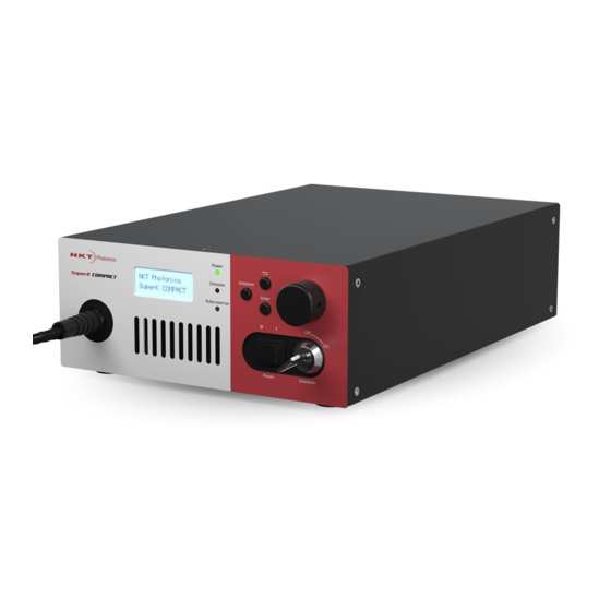
Front panel controls Front panel controls The front panel features are highlighted in Figure 5. The panel includes user controls and a display to operate the laser. Figure 5 Front panel features Optical output fiber (laser aperture) 5 Navigation buttons LCD display menu 6 Selection dial Status LEDs... -
Page 27: Selection Dial
Rear panel interfaces Enter button When pressed this button either enters a selected menu sub-level or confirms a setting or function within the menu system. Selection dial The dial is used with the display and return button to configure, operate and view the laser status. -
Page 28: Ac Input
The signal is created from the analog signal and transmits a positive logic signal when an optical pulse is emitted. USB connector Connect a PC to this port in order to manage the laser using NKT Photonics CONTROL software. Note: To connect to the port, the PC must have NKTP USB port drivers installed. -
Page 29: External Bus
Configuration and operation overview External bus This 15 pin port connects power, communications and the interlock circuit to any external accessories used with the laser. When no accessories are used with the laser, connect the interlock defeater plug onto this port – see “External bus”... -
Page 30: Laser Accessory Management
For information on connecting the bus, see "Connecting accessories with the external bus". Status LEDs Rear panel LEDs The rear panel houses four status LEDs shown in Figure 7 and described in Table Figure 7 SuperK COMPACT rear panel status LEDs... -
Page 31: Front Panel Leds
ON Red The DC supply voltage to the main controller is too low/ high. No power is connected. Flashing Green The SuperK COMPACT is transmitting serial data to a connected PC. No transmitted data detected ON Green USB serial port is connected and the driver is installed and configured correctly. -
Page 32: Chassis Labels
Chassis labels Chassis labels The SuperK COMPACT chassis includes multiple labels that indicate hazards and regulatory or manufacturing information. The labels are located on the rear panel, the armored fiber cable, and the collimator as described in Table 4 with... -
Page 33: Operating The Laser
SECTION 2 OPERATING THE LASER This section describes how to manage and operate the laser and includes the chapters: • “Front Panel Controls” on page 35 • “Connecting and Turning ON the Laser” on page 45 • “CONTROL Interface” on page 51... -
Page 35: Front Panel Controls
Front Panel Controls Overview The front panel features an LCD operations menu and controls that can be used to configure and operate the laser. The menu items available are listed in Table Table 5 Front panel LCD menu items Menu Item Function Top menu level Displays the trigger mode, laser pulse... -
Page 36: Menu Items
Menu items Menu items Top menu level The top menu level (Figure 9) displays the following: • Trigger mode (Operating mode) • Pulse Frequency • Number of burst pulses (count) At the bottom of the top menu level screen, the laser’s status is displayed. Status messages include the: •... -
Page 37: Figure 11 Interlock Circuit Open Notification
Menu items Top level menu - Interlock notification If the interlock circuit (See “Key switch and interlock safety” on page 29) is open or shorted to ground, the LCD menu displays one of the following alarms: • External interlock (Figure 11) –... -
Page 38: Operating Mode
A burst of pulses at the set repetition rate is emitted each time the laser receives a telegram to initiate the burst. To send telegrams to the laser over it’s RS-232 serial or USB interface, you must implement the NKT Photonics Software Development Kit (SDK). The SDK can be downloaded from:... - Page 39 Menu items Note: The telegram to initiate the burst is sent to register 0x34 (Burst pulses). Burst number (Burst pulses) and repetition rate (Frequency) can be set with either the front panel sub-menus or with registers 0x34 and 0x33 respectively. Note: Software burst mode is not supported using CONTROL.
-
Page 40: Frequency
Menu items Table 6 External gate modes – pulse emission truth table Operating mode COAX trig input Industrial trig input Output pulses Disabled High Continuous pulses External gate ON High Continuous pulses High High Continuous pulses Continuous pulses High Disabled External gate OFF High Disabled... -
Page 41: Burst Pulses
Menu items 3. Press the enter button to enter the Power % setting menu. 4. Turn the selection dial to set the power level. 5. Press the return button twice to return to the top level menu. Note: The laser’s frequency is directly proportional to its output power and hence automatically adjusts as the power level setting is changed. -
Page 42: Watchdog Timer
Menu items 3. Press the enter button to enter the Coax trig level setting menu. 4. One position of the trigger detection voltage level digits flashes. This indicates the selection dial can modify them. 5. Turn the selection dial to set the digit(s). 6. -
Page 43: Display Backlight
Menu items Display backlight The brightness of the display backlight can be adjusted in percent, to set it: Press the enter button to enter the laser’s sub-menus. 2. Turn the selection dial until the menu displays System menu - Display backlight. -
Page 44: Firmware Versions
Caution: Do not turn on the laser if it has been exposed to temperature and hu- midity beyond the operating specifications. The SuperK COMPACT is designed to operated in a non-condensing environment from +18 to +30°C (or 35°C). Before turning on the laser, allow it at least 30 minutes to reach room temperature. Turn- ing on a laser that is too cold or hot may lead to the system being damaged. -
Page 45: Connecting And Turning On The Laser
Connecting and Turning ON the Laser The SuperK COMPACT laser can be managed using NKTP CONTROL software installed on a PC. This chapter focuses on: • How to obtain and install the CONTROL software • Connect a PC using USB connectivity •... -
Page 46: Procedure 1 Connecting A Pc To The Laser Using A Usb Cable
If necessary, wait for the Windows device manager to install the USB drivers for the connection. Launch the CONTROL software by either: • clicking on Windows – Start – Programs – NKT Photonics –CONTROL – or – • double clicking the CONTROL shortcut on the desktop The CONTROL window opens. -
Page 47: Controlling Laser Emission
Do not turn on the laser if it has been exposed to temperature and humidity be- yond the operating specifications. The SuperK COMPACT is designed to operated in a non-condensing environment from +18 to +30°C (or 35°C). Before turning on the laser, al- low it at least 30 minutes to reach room temperature. -
Page 48: Errors
Controlling laser emission Procedure 2 Turning ON the laser Action On the front panel of the laser, turn the key switch on the laser’s front panel to the ON position. When the key is in the ON position, the laser emission can be enabled from CONTROL software. -
Page 49: Turning Off The Laser
Controlling laser emission Turning OFF the Follow the steps in Procedure 3 to turn off or disable laser emission. laser Procedure 3 Turning OFF the laser Action Turn OFF laser emission by clicking on the software Emission button. The Emission button light turns from RED (ON) to green (OFF). - Page 50 Controlling laser emission...
-
Page 51: Control Interface
CONTROL Interface CONTROL overview The CONTROL user interface includes multiple panels and a selection of menu drop down items in the upper left corner. Using the Window drop down menu, you can add or remove displayed panels. The panels can also be dragged within the main window or into separate windows. -
Page 52: Relocating Panels
CONTROL overview Relocating panels The panels displayed by CONTROL can be dragged to any location within the main interface or into a separate floating panel. Procedure 4 describes how to move a panel: Procedure 4 Relocating panels Action Left Click and hold the top title bar of the panel. While holding the left mouse button down drag the panel to another location in the main window. -
Page 53: Toggling Panels
CONTROL overview Toggling panels Use the Menu > Window drop down menu to check and uncheck panels to be viewed. Figure 26 Toggling panel visibility Check the panels to display them Note: Clicking the X in the upper right corner of any panel will also close it. Connecting to the When CONTROL is launched, the Welcome panel is displayed as in Figure... -
Page 54: Status Panel
Status panel Status panel The Status Panel provides status indicators, error messages, emission control function and a CONTROL settings menu. Figure 28 Status Panel Status indicators The panel displays the following indicators: Trigger ▲ ▼ (up) and a (down) arrow indicators display the status of the trigger signal measured at a trigger input. - Page 55 Status panel Note: If the frequency of the input trigger signal is very low i.e. 10 Hz, then the ar- row states change at roughly the rate of the trigger signal pulses. At higher trigger signal frequencies, the arrows appear steady ON. Note: Visible flashing of the arrows may also indicate that the trigger signal level is slightly low, such that only a few of the trigger signal pulses are detected.
-
Page 56: System Info
Control settings “Connecting the safety interlock” on page System info The System Info section shows the following: • Laser Serial Number • Laser Firmware Revision Note: System info is only displayed when the option is checked in “View” on page Emission button The emission button turns the laser emission ON or OFF –... -
Page 57: Figure 30 Watchdog
Control settings Figure 30 Watchdog 1 to 255 seconds 0 is OFF View The View settings control the display items in the status panel and the front LCD panel: System info – check the box next to “System info” to toggle on displaying the the system’s serial number and firmware version within the status panel. -
Page 58: Control Menu
CONTROL menu CONTROL menu There are five drop down menus in the main control window as highlighted in Figure 32. Click on the items in the menu to reveal the drop down menus. Figure 32 Menu items Menu Item Function File Exits the CONTROL program Disconnect... -
Page 59: Log Downloader
NKT Photonics support personnel. Log downloader If your laser requires support from NKT Photonics, our support engineers may request that you send the log files collected by the laser. You can use the log downloader tool to save the laser log files to your CONTROL PC. -
Page 60: Extensions Overview
This tool is used to view the installed extensions (plugins) that are included with overview CONTROL. The extensions are found in the following folder: C:\Program Files (x86)\NKT Photonics\NKTP CONTROL\Plugins To view the extensions, open the Tools menu and click on Extensions Overview. The Extensions Overview window will be launched as shown in... -
Page 61: Figure 33 Extensions Overview
CONTROL menu Figure 33 Extensions Overview Note: To show a short description of the release notes as seen in Figure 33, hover the mouse pointer over the “Release notes” text The PubCompactLib.dll details highlighted in Figure 33 shows the version of the .dll file (1.1.2.303), the included extensions and which module types they support. -
Page 62: Trigger Mode
Trigger mode Trigger mode Using NKTP CONTROL, you can select to operate the laser using one of five trigger modes. The modes determine when and how pulses are emitted. When a trigger mode is selected, the Control Panel shows the settings relevant for the mode. -
Page 63: External Trigger
Trigger mode External trigger One pulse (Figure 35) is emitted each time the leading edge (low to high transition) of a trigger signal is detected on one of the external trigger input ports. The rising edge of the trigger signal must reach the threshold for the detection voltage level set for the port. -
Page 64: Gated Trigger
Trigger mode Figure 36 Burst mode saved without PDF Content. saved without PDF Content. To Place or open this file in other To Place or open this file in other applications, it should be re-saved from applications, it should be re-saved from Adobe Illustrator with the "Create PDF Adobe Illustrator with the "Create PDF Compatible File"... -
Page 65: Gated Trigger Inverted
Trigger mode Note: When using the Front panel controls, the Gated trigger mode is set using “External gate on mode” described on page Gated trigger When a logic low level signal is detected at both of the trigger input ports, pulses inverted (Figure 38) are continuously emitted at the set repetition rate. -
Page 66: Controls
Controls Warning: Although some operating modes can stop pulses from being generated, the laser must still be regarded as having emission on. Stopping pulses by using the input trigger signals in a certain combination, is considered an unsafe method to disable emission. Table 7 Gated modes –... -
Page 67: Power
Controls Power You can set the output power in percent using the slider shown in Figure 41. You can also enter the power in percent using the text input field at the upper right corner. Figure 41 Repetition rate slider and text input field Note: Output power is modified my setting a pulse repetition rate proportional to the power level desired. -
Page 68: Application Log Panel
Application log panel The Application Log panel displays and logs the communication of status messages. The log can be used to debug connection issues between CONTROL and NKT Photonics devices. The panel displays and timestamps the following types of log messages: •... - Page 69 Device monitor Parameter Description SysType The system type, default 0 – can be used to describe system variants and is read from the module. Name The name of the connected device module. The device module part number. Mode The mode or status of the connected module: connected, disconnected, or disabled Status bits The actual status bits read from the connected module.
- Page 70 Device monitor...
-
Page 71: Installing The Laser
SECTION 3 INSTALLING THE LASER This section describes how to install the laser and includes the chapters: • “Mechanical Installation” on page 73 • “Connecting the Laser” on page 75... -
Page 73: Mechanical Installation
Mechanical Installation Caution: For reliable operation, the laser should not be exposed to corrosive agents or excessive moisture, heat or dust. General installation Installation surface The laser must be installed on a level surface that is free from vibrations. Environment The ambient temperature surrounding the laser should be stable and free from temperature fluctuations such as heat or cold sources. - Page 74 General installation...
-
Page 75: Connecting The Laser
Connecting the Laser Before operating the laser, follow the procedures in this chapter to ensure its correct and safe operation. For information on how to connect: • the Safety Interlock – see “Connecting the safety interlock” on page 75 • Power –... -
Page 76: Figure 45 Interlock Connected To A Door Switch - Laser On
Open Interlock Monitor Laser Control Circuitry Reset Shutdown Laser Caution: Do not short-circuit the Interlock input. Short-circuiting the interlock cir- cumvents safety regulations and NKT Photonics does not take liability for any in- juries or damage caused by doing so. -
Page 77: Connecting Power
Connecting power Caution: The switch connected to the interlock must be of an approved type. Fur- ther, the switch must be installed in a manner so that its operation cannot be fixed in the open state using a tool to defeat its operation. Warning: If the interlock is bypassed, personnel may be exposed to hazardous la- ser radiation. -
Page 78: Connecting The Optical Output
Connecting the optical output Procedure 8 Connecting power Action Connect the AC cable supplied with the laser to the rear 3-pin IEC power input connector. Connect the AC cable to a local AC mains supply. Press the power toggle button to the ON position. (The switch is next to the keyswitch on the front panel.) Connecting the optical output Warning:... -
Page 79: Collimator Installation
Connecting the optical output Collimator The collimator is constructed so that its sleeve is inserted into a holder or a installation receptacle of a next stage optical device such as a SuperK accessory. To install the collimator, follow the instructions in Procedure Procedure 9 Installing the Collimator Action... -
Page 80: Connecting Accessories With The External Bus
Figure 49 Collimator Installed in a Holder Receptacle Caution: NKT Photonics recommends to ensure there is firm thermal contact be- tween the collimator and its surroundings. If the thermal contact between the col- limator and its surroundings is poor, the collimator can become significantly warmer than its surroundings. -
Page 81: Table 9 External Bus Port - Connecting Accessories
Note: Appendix C for a pinout description of the External Bus Figure 51 External Bus circuit - with no accessories used SuperK COMPACT External Bus Bus Defeater Connector Figure 52 External Bus circuit - with multiple accessories in a daisy chain... -
Page 82: Trigger Input Ports
The voltage level is adjustable using either the front panel controls (“Coax trig level” on page 41) or NKT Photonics CONTROL management software (“Trigger level” on page 67). To reduce noise sensitivity, the port has a hysteresis of approximately 1%. -
Page 83: Industrial Trigger Input
Synchronization output ports Note: If the port is not in use, ensure to set the trigger level threshold (see “Trigger level” on page 67) to a level well above zero volts to avoid noise inadvertently trig- gering the laser. Industrial trigger This input is isolated electrically from the laser. -
Page 84: Logic Pulse Output
Synchronization output ports Figure 54 Analog trigger output timing advance Trigger output pulse Analog pulse output time 45-55 ns ±2 ns Optical pulse Optical ouput time Table 12 Analog pulse output Parameter Value 50 Ω[ Output impedance 2 V maximum Pulse voltage 10 ns Pulse width... -
Page 85: Table 13 Logic Pulse Output
Synchronization output ports Figure 55 Logic pulse output vs. Analog pulse output Analog pulse output time 12 ns ± 1 ns 1.8 µs ± 0.2 µs High Logic pulse output time 45-55 ns ±2 ns Optical pulse Optical ouput time Note: As mentioned for the Analog pulse output, the actual total advance can vary and is dependent on the final application setup, where the length of the trigger ca-... -
Page 86: Example Synchronization Circuit
A general diagram of a synchronization circuit is shown in Figure circuit Figure 56 Example Pulse Circuit Emission pulses SuperK COMPACT Analog output pulse Analog pulse (RG223 Cable) Synchronizer Sensor Control... -
Page 87: Figure 58 Synchronization With Pulse Burst Illumination
Synchronization output ports By using burst mode as shown in Figure 58, a subject can be illuminated by multiple pulses, increasing the dosage of light energy delivered to the subject. Figure 58 Synchronization with pulse burst illumination Trigger onset Triggers generation of a burst of optical pulses and analog trigger out pulse. COAX trig input time Analog trigger... - Page 88 Synchronization output ports...
-
Page 89: Appendices
APPENDICES The appendices include: Appendix A on page 91 Specifications • Appendix B on page 93 Service and Support • Appendix C on page 95 External Bus Pinout • Appendix D on page 97 Fiber maintenance • Appendix E on page 99 Accessories •... -
Page 91: A Specifications
Waist location @500 nm Optical Output Collimated Repetition rate dependant For ± 0.5 % contact NKT Photonics Table 15 Interfaces RS-232 serial COM - 9 Pin D-Sub Female Connector PC and micro processor interfaces USB 2.0 - Type B Female Connector Coax trigger inpt: BNC -7 to 7 V analog input –... -
Page 92: Table 17 Electrical
Table 17 Electrical Input 100-240 VAC 50-60 Hz AC Power T 2A, 250 V Fuse types 20-30 W Typical power consumption – emission ON 50 W Maximum power consumption – emission ON 100 W Maximum power consumption with accessory Repetition rate set to 20 kHz. Accessory connected to COMPACT external bus connector. -
Page 93: B Service And Support Information
Service and Support Information Servicing the laser The SuperK Extreme series lasers have no user serviceable components. In case of malfunction, contact NKT Photonics using the support website listed below under Support contact details. End of line safety tests according to EN61010-1 Annex F are performed on all Laser chassis. -
Page 94: Support Contact Details
Support contact details Support contact details If you need help or have questions regarding your SuperK COMPACT laser or its accessories, contact NKT Photonics through our support website below: Support website 1. Go to: https://www.nktphotonics.com/lasers-fibers/support/technical-support-and- customer-service/ 2. Scroll down and click or press: 3. -
Page 95: C External Bus Pinout
External Bus Pinout Table 18 External bus pinout Name Description Not connected RS485- Negative (inverted) RS485 data signal Interlock loop+ Positive connection of the safety interlock loop. Connect pin 3 to pin 4 Interlock loop- to enable laser emission. Interlock loop- Negative connection of the safety interlock loop. -
Page 97: D Fiber Maintenance
Fiber Maintenance Fiber tip cleaning Only use cleaning tools specifically designed for use with optical fibers. Always use extreme caution when cleaning fibers. Examples of appropriate cleaning tools are: Lens cleaning tissue (lint free wipes) see Figure 62 Optical fiber cleaning tool see Figure 63 Figure 62 Lens cleaning tissue - lint free Figure 63 Optical fiber cleaning tool... -
Page 98: Damaged Facet
3. Continue this "quick polish, check beam" process until a well-formed beam is obtained. If you do not obtain a good beam profile after polishing, the connector may be damaged. Return the laser to NKT Photonics for repair. Note that this type of repair is not covered by warranty. -
Page 99: E Accessories
This appendix provides a brief overview of the accessories available for your laser. Table 19 lists the accessories and their functions and provides a link to descriptions of the SuperK COMPACT advanced accessories. Table 19 SuperK COMPACT accessories Advanced accessories Function... -
Page 100: Superk Varia
SuperK VARIA The VARIA accessory acts as a bandpass filter when connected to the collimator of the SuperK COMPACT laser. A portion of the beam from the SuperK COMPACT is diverted to the VARIA’s bandpass filter which removes the light wavelengths that fall outside a variable wavelength range. -
Page 101: Superk Select
Connect, a small aperture is not required; the delivery system aperture will provide the suppression. Output beam specifications AOTF types must be specified when ordering a SuperK COMPACT. The type of AOTF determines the possible wavelength range and bandwidth that can be diffracted from the crystal. -
Page 102: Table 21 Select Aotf Types
SuperK SELECT Table 21 SELECT AOTF types AOTF type Wavelength range (nm) Bandwidth (nm) UV-VIS 400-650 1.8-8.5 VIS (1x) 430-700 0.5-1.85 VIS (4x) 450-700 2.5-8.5 VIS-nIR 500-900 3.5-14 nIR1 640-1100 1,5-5 nIR2 800-1400 2.6-9.6 1100-2000 6.4-19.8 As noted earlier, the tuned beam which is defracted from a SELECT crystal filter will also include a number of n’th order side lobes. -
Page 103: Superk Lltf
SuperK LLTF SuperK LLTF The Laser Line Tunable Filter (LLTF) Contrast accessory provides a tunable and extremely narrow bandpass filter with out-of-band (OOB) suppression in the order of 60 dB. The filter can be continuously tuned over the entire spectrum of the supercontinuum laser, converting the wide band beam to a finely tuned picoseconds laser. -
Page 104: Superk Split
SuperK SPLIT SuperK SPLIT Use the SuperK SPLIT to divide the SuperK COMPACT emission into two separate spectral outputs. The SPLIT is a passive filter and it is available in two standard models where the spectral outputs are configured as either: •... -
Page 105: Superk Connect
SuperK CONNECT SuperK CONNECT The CONNECT is a single mode fiber coupling device which can terminate to a collimator or either FC /PC or FC/APC connectors. As a fiber deliver system, CONNECT can be used with the laser or its accessories. It combines high coupling efficiency with power handling up to 500 mW over a spectrum from 400 to 2000 nm. -
Page 106: Polarization Spacer
Polarization spacer Polarization spacer This is a spacer and alignment ring that fits onto the laser collimator. It MUST be used when inserting the collimator into an accessory optical input receptacle. The ring has an alignment pin which aligns the polarization of the laser emission properly with the accessory optics. -
Page 107: F Control Software
Control Software Installing CONTROL Download the software from: https://www.nktphotonics.com/lasers-fibers/support/software-drivers/ Follow the steps in Procedure Procedure 10 Installing CONTROL Action On the PC, launch the installer package and then click the Installer Run button. The installation wizard appears. Click Next to continue. - Page 108 Installing CONTROL Action Accept to use the default installation directory or select another directory by clicking the Browse button. Click Next to continue. Uncheck the components you do not require. By default, all components will be installed. Click Next to continue. Read the End-User License Agreement, and select: “I accept the license.”.
- Page 109 Installing CONTROL Action The wizard will create a start menu folder with program short-cuts. Use the default name or enter a new name for the folder. Click Next to continue. Check the box to create a desktop shortcut to access Control.
- Page 110 Installing CONTROL Action Click Install to install NKTP CONTROL software on your Click Cancel if you want to abort the installation.. The wizard displays a progress meter for the installation. Note: a normal install should only take a few seconds. Click Next to install the UART drivers for the PC USB port.
- Page 111 Installing CONTROL Action The drivers will be installed. The Silicon Labs drivers is installed successfully. Click Finish to end the installation wizard. CONTROL is now installed. Check the Run box to launch CONTROL when the Finish button is clicked. Click Finish.
- Page 112 Installing CONTROL...
-
Page 113: G Collimator Output Beam Properties
Collimator Output Beam Properties Beam parameter definitions Figure 71 Beam parameters θ Definitions: : Beam Diameter at waist location θ : Full angle divergence after waist : Rayleigh length Waist location Figure 72 Beam waist location Waist width General Laser output definition Divergence Waist location... -
Page 114: Beam Diameters In The Visible Range
Beam diameters in the visible range Beam diameters in the visible range Full angle beam Figure 73 Full angle beam divergence θ divergence θ SuperK Compact Collimator Divergence Wavelength [nm] Beam diameter at Figure 74 Beam diameter at waist location W waist location W SuperK Compact Collimator waist width 1200 1000... - Page 115 SuperK COMPACT Product Guide Revision 1.0 06-2021 W-10456...
Need help?
Do you have a question about the SuperK COMPACT and is the answer not in the manual?
Questions and answers