Table of Contents
Advertisement
Quick Links
Advertisement
Table of Contents

Related Manuals for NKT Photonics PILAS


Summary of Contents for NKT Photonics PILAS
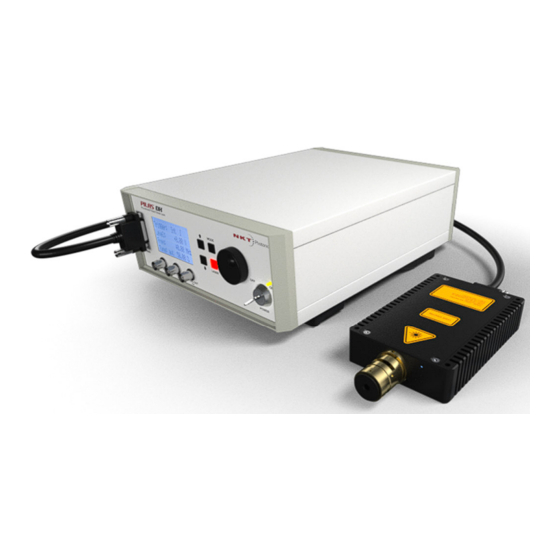
- Page 1 PILAS picosecond pulsed diode laser Product Guide sample manual only - not to be delivered with systems Advanced Laser Diode System A.L.S. GmbH, Schwarzschildstr. 6, 12489 Berlin, Germany -NKT Photonics A/S, Blokken 84, 3460 Birkeroed, Denmark...
- Page 2 Issue: 3BP3.1 Published: April 2023 Copyright © 2021 by A.L.S. GmbH / NKT Photonics A/S. All rights reserved. Reproduction or translations of any part of this work is prohibited.
-
Page 3: Table Of Contents
3.3.2 Start laser with internal triggering ......................11 3.3.3 Start laser with external triggering (TTL input) ................. 11 3.3.4 Start laser with external triggering (Adjustable input) ..............11 3.3.5 Start with remote software PILAS Serial Console................12 3.4 Controller LCD Menu ............................13 3.4.1 Start Screen ............................... 13 3.4.2 Main Menu .............................. - Page 4 Figure 10 EGI-D2-40 front panel ..........................10 Figure 11 NKTP support website ..........................12 Figure 12 PILAS serial console screenshot......................12 Figure 13 Start screen and two possible start error messages ..............13 Figure 14 Main menu (left with internal trigger, right with eternal TTL trigger) ......... 13 Figure 15 Setup menu ...............................
-
Page 5: General
The information given in this document is subject to change without notice. Copyright Advanced Laser Diode Systems A.L.S. GmbH 2021. A.L.S. GmbH is wholly owned subsidiary of NKT Photonics A/S, Blokken 84, 3460 Birkeroed, Denmark All rights reserved. Reproduction, adaptation, or translation without prior written permission is prohibited, except as allowed under the copyright laws. -
Page 6: Laser Safety
1.4.2 Laser Class This PILAS laser system is classified as class 3B laser product according to IEC 60825-1:2014 during all procedures of operation. Class 3B laser systems require wearing certified laser safety glasses. -
Page 7: Label Location
1.4.4 Label Location The shown laser head and labels are samples: Warning label for laser radiation is attached on top of the laser head near the laser emission aperture as shown in the diagram. Laser aperture label is attached on top ... -
Page 8: Introduction
Repetition rates of up to 40 MHz, very low jitter and different triggering possibilities make the PILAS a flexible and reliable system suitable for a wide range of applications. -
Page 9: Operation
3 Operation The following chapters describe controller settings. Nothing needs to be adjusted on the laser head to start operation. 3.1 Installation Set up controller and laser head in stable position. Connect the power supply cable to the controller (100V - 240V, 50Hz - 60Hz). -
Page 10: Front Elements Control Unit
11. Power LED, green 3.2 Controller button/rotary knob The digital control unit of the PILAS is operated by four keys UP, DOWN, MODE, ON and rotary knob (see image). You can select the different menus by pressing MODE keys. The UP and DOWN keys are for selections within the menus. -
Page 11: Remote Control
3.3 Remote Control Only one of the USB or the RS232 interfaces should be connected and used. Connecting via computer RS232 COM Port will not require any drivers. Connecting via USB will require the installation of a virtual com port chip set driver (VCP) from FTDI. The controller will appear as virtual COM port afterwards. Properties Connection UART interface support 8 data bits, 1 stop-bit... -
Page 12: Start With Remote Software Pilas Serial Console
3.3.5 Start with remote software PILAS Serial Console You can download a simple serial console for sending commands and receiving the output on the NKTP support website (description or look can change): This software is available for Windows in a 64 and 32 bit version. -
Page 13: Controller Lcd Menu
3.4 Controller LCD Menu The following adjustable laser parameters will be set by software menu: pulse repetition rate / frequency TUNE (pulse amplitude and width) Temperatures (only in debug mode) CW mode (only if ordered) Trigger methods a) internal 25Hz to 40 MHz b) external single shot to 40 MHz ... -
Page 14: Tune Setup
With the UP and DOWN keys, you can navigate within the setup menu. The selected menu is marked by “<” sign on right side. This is valid also for the next menus. For switching to desired menu press MODE button. The following menus are accessible from here: Main Menu <... -
Page 15: Frequency Setup
3.4.5 Frequency Setup Figure 17 Frequency menu The maximum adjustable frequency can be found in the test report or purchase information (40MHz standard). In the second row you can select between “coarse” and “fine” frequency resolution for internal triggering. Selection is done with the rotary knob. Mode coarse: With this option the frequency is adjusted in the third row in predefined steps. -
Page 16: Cw Mode
We recommend checking the controller trigger output signal because the trigger output is linear to the signal the laser diode is seeded with. Optimize the trigger threshold and (if possible) amplitude until the trigger output is clean and stable (no double or multiple pulses within a period). The impedance for all BNC plugs is 50. -
Page 17: Optical Head
4.1 Handling and Adjustment The following chapters describe the main optics shown in the picture above that can be used in conjunction with PILAS-systems. You will find the optics used for your system in the PILAS-test report attached to the manual. -
Page 18: Fiber Coupler (Removable)
4.2.2 Fiber Coupler (removable) The “FC” option is delivered with a fiber coupling unit and a single or multimode mode fiber attached to it as standard. The single mode fiber can be PM fiber (polarization maintaining) or standard single mode fiber. -
Page 19: Pilas Optical Specifications
The laser beam is linear polarized with a ratio of 100:1 or 20dB. The direction of polarization is parallel to the bottom/table plane and perpendicular to propagation axis (red arrow). The figure shows the collimated elliptical output beam of PILAS (blue ray) and the direction of polarization (red arrow). Figure 26 Polarization 4.4.3 Peak Power Calculation... -
Page 20: Timing Jitter
4.4.4 Timing Jitter The measured timing jitter reflects fluctuations of the optical pulse arrival time (at 50% amplitude) in reference to the controller electrical trigger out signal (from which also the optical signal is generated inside the laser head). be the measured time deviation from the ideal optical pulse rising flank position for measurement (sampling oscilloscopes... -
Page 21: General Specifications
5 General Specifications 5.1 Control Unit EGI-D2-40 Internal trigger: Repetition rate 25 Hz to 40 MHz Frequency resolution 1Hz to 2kHz (depends on frequency) Frequency stability max 200ppm @40MHz (depends on frequency) External trigger input (TTL): Amplitude +5 V max. Trigger level states Input impedance 50 ... -
Page 22: Rs232 Commands V1.1.Aee
6 RS232 Commands v1.1.AEe version? -> return device information (software, hardware version, serial numbers, wavelength, options) EIGserial? -> return controller serial number LHserial? -> return laser head serial number state? -> return system state information (sent at controller boot up to listening COM port) mState? ->...
Need help?
Do you have a question about the PILAS and is the answer not in the manual?
Questions and answers