
Related Manuals for NKT Photonics MIKRO C15


Summary of Contents for NKT Photonics MIKRO C15
- Page 1 Koheras MIKRO Low Noise Single Frequency Laser Module PRODUCT GUIDE Item: 800-610-01 Customer Revision: NKTP Revision: Release Date: 03-2022...
- Page 2 PRODUCT GUIDE This guide includes the following NKT Photonics Lasers: Koheras MIKRO Low Noise Single Frequency Laser Module Previously referred to as the Koheras BASIK MIKRO. W-10456...
-
Page 3: Guide Overview
GUIDE OVERVIEW This product guide is intended to provide functional, operational and installation information for the Koheras MIKRO laser modules. The guide is divided into three sections: • Koheras MIKRO Description - introduces the laser, its functionality, interfaces and chassis variants. •... - Page 4 • Chapter 5 “Software Development Kit” — Includes descriptions and procedures for certain key settings that can be configured using the SDK. • Chapter 6 “Mechanical Installation” — Includes information and procedures on how to correctly install the laser chassis. Procedures within this chapter focus on providing adequate temperature regulation.
- Page 5 Date Revision Changes 2022-01 Null change • 2022-02 1.2 Product name changed to Koheras MIKRO from Koheras BASIK MIKRO. • Added scales drop down selection description in Procedure 3 on page • Added power scale drop down selection of wavelength or offset to section “Power mode”...
-
Page 7: Table Of Contents
CONTENTS Guide Overview ....................3 Terminology ..................3 CONTENTS ....................6 TABLES ......................11 FIGURES ...................... 13 PROCEDURES .................... 15 MIKRO DESCRIPTION Section 1 1 Laser description ................... 19 Theory of operation ................19 Module variants ..................20 Configuration ID ................. 20 Center wavelength ................ - Page 8 Electrical Interfaces ................. 25 Main electrical interface ..............26 Fast wavelength modulation input ............. 26 Laser Control ..................26 User interface ..................26 Status LEDs .................... 27 Module labels ..................28 OPERATING THE LASER Section 2 2 Communicating with the Laser ..............31 CONTROL software ................
- Page 9 CONTROL menu items ................46 Key Updater tool ................46 Log Downloader ................. 47 Extensions Overview ................. 48 CONTROL – Control panel..............50 Power mode ..................50 Current mode ..................50 Device Monitor..................51 Application log ..................52 5 Software Development Kit ................53 Tuning the wavelength ................
- Page 10 Appendices A Specifications ....................67 B Service and support Information ..............69 Servicing the laser .................. 69 Opening the module casing ............... 69 WARRANTY VOID IF REMOVED Label ........... 69 Support contact details ................70 Support website ................. 70 Online support web-page ..............70 Shipping address ................
-
Page 11: Tables
TABLES Table 1: MIKRO output specifications .............. 20 Table 2: Recommended Power Modes ............22 Table 3: Optical interface specifications ............24 Table 4: Connectors ..................25 Table 5: Status LEDs..................27 Table 6: Module labels ..................28 Table 7: CONTROL panels and menu items............ 39 Table 8: Device Monitor parameters .............. -
Page 13: Figures
FIGURES Figure 1: Working panel of the MIKRO ............19 Figure 2: Frequency response using wavelength modulation ......21 Figure 3: USB-RS485 adapter ................. 24 Figure 4: MIKRO equipped with fiber cord and FC/APC connector ....24 Figure 5: Front panel electrical connections ............ 25 Figure 6: Status LEDs .................. - Page 14 Figure 29: RS-485 adapter connected to a door switch (open position) ..62 Figure 30: Power supply .................. 63 Figure 31: Mechanical dimensions ..............68 Figure 32: Warranty seal ................. 69 Figure 33: Main electrical interface PIN layoutl ..........71 Figure 34: RS-485 adapter ................
-
Page 15: Procedures
PROCEDURES Procedure 1: Connecting CONTROL to the laser ........... 32 Procedure 2: Connecting the Generic User Interface to the laser....34 Procedure 3: Enable emission using CONTROL ..........36 Procedure 4: Enable emission using the SDK Generic User Interface ... 37 Procedure 5: Relocating panels .............. -
Page 17: Mikro Description
SECTION 1 MIKRO DESCRIPTION This section provides a description of the laser and its chassis types. It includes the following topics: • “Laser description” on page 19 • “Module variants” on page 20 • “Laser features” on page 20 • “Miscellaneous”... -
Page 19: Laser Description
Laser description The Koheras MIKRO is an industrial single frequency fiber laser housed within a micro-casing. Further, the laser and its micro-casing (referred to as a module) is designed for integration with industrial applications where its built-in laser control circuits can continuously monitor the laser’s performance. Using these monitoring circuits, the laser supports applications that demand ultra-low noise, high wavelength stability and ultra-stable single frequency operation unaffected by mode hops. -
Page 20: Module Variants
Module variants Module variants Koheras MIKRO modules are available in two variants: the E15 and C15 modules. The modules are classified by their phase noise, intensity and power level. Table 1 lists the technical differences between the two variants. Table 1 MIKRO output specifications Module Type Maximum Output Power Phase Noise 10 mW Ultra-low... -
Page 21: Fast Wavelength Modulation
Laser features the laser cavity length also changes due to thermal contraction or expansion. Further, the temperature of the laser cavity itself also changes such that the laser wavelength changes in response to both thermo-optic and physical changes in the optical path length. See “Tuning the wavelength”... -
Page 22: Auto-Start
Laser features • Power mode – the power out of the fiber laser is held at a fixed level. The mode set depends on both the model and the application, refer to Table 2 for the recommended mode to use. See “Setting the operating mode”... -
Page 23: Power Verification
An external 12 VDC power source (not included) is required. Power is connected to the main electrical interface connector, see “Main electrical interface” on page Note: The NKT Photonics RS-485 adapter kit includes a suitable power supply for the laser. See “Accessories” – “USB-RS485 adapter kit”. -
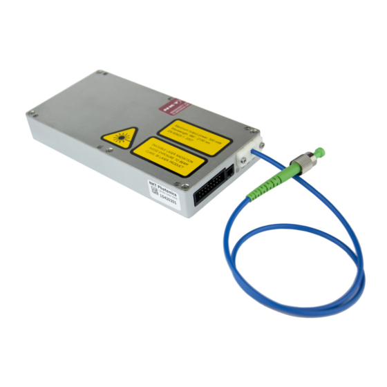
Page 24: Optical Interface
Table 3 Optical interface specifications Parameter SMF28 PM 1550 ~10 microns ~10 microns Fiber mode field diameter Numerical aperture 0.14 0.125 Mode field diameter is approximate - contact NKT Photonics Support contact details on Support for more information ( page 70... -
Page 25: Electrical Interfaces
Electrical Interfaces Electrical Interfaces The laser is equipped with two standard electrical connectors. The connectors provide the laser with the following electrical interfaces: • 12 VDC power • RS-485 serial communications • a safety interlock circuit • emission control (5V logic) •... -
Page 26: Main Electrical Interface
User interface The laser modules and any associated accessories are controlled using either NKT Photonics CONTROL management software installed on a PC or the NKTP Software Development kit (SDK). If you are using the GUI, it can control the laser’s emissions and adjust its power and pulse rate settings. -
Page 27: Status Leds
Status LEDs The PC or custom microprocessor must connect over the laser’s RS-485 serial interface (see “Main electrical interface” on page 26). Section 2 includes multiple chapters describing the GUI and procedures related to controlling the laser with it. Note: An optional USB to RS-485 adapter is available to connect a standard PC to the laser. -
Page 28: Module Labels
Module labels Note: the laser until you are familiar with the controls and have O NOT OPERATE taken all precautions necessary as described in the Koheras MIKRO Safety, Han- dling and Regulatory Information. Module labels The Koheras MIKRO modules include multiple labels that indicate hazards, regulatory, or manufacturing information. -
Page 29: Operating The Laser
SECTION 2 OPERATING THE LASER This section describes how to manage and operate the laser and includes the chapters: • “Communicating with the Laser” on page 31 • “Turning ON the Laser” on page 35 • “Using CONTROL” on page 39 •... -
Page 31: Communicating With The Laser
RS-485 adapter. Using the adapter you can test the laser module when integrating it into a final application. CONTROL software The laser is shipped with the NKT Photonics CONTROL software installer on a USB key. You can also download the most recent CONTROL software from the following link: https://www.nktphotonics.com/lasers-fibers/support/software-drivers/... -
Page 32: Connecting Control To The Laser
Note: For a full description of the SDK, registers and the Generic User Interface, refer to the NKT Photonics document: SDK Instruction Manual. The manual is in- stalled along with the SDK components when the SDK installer is run. Connecting CONTROL to the laser You can manage the laser over its RS-485 serial connection connected to a PC with CONTROL software. -
Page 33: Connecting The Sdk Gui To The Laser
Also for test purposes, use the included NKT Photonics RS-485 adapter to connect the laser to the PC’s USB port and also to a 12 VDC power source. Follow the steps in Procedure 2 connect the SDK GUI to the laser. -
Page 34: Procedure 2 Connecting The Generic User Interface To The Laser
Connecting the SDK GUI to the laser Procedure 2 Connecting the Generic User Interface to the laser Action 1. Using the IDC 16 pin to Ribbon Cable DB-15 ribbon cable, Safety interlock pins connect the NKT Photonics RS-485 adapter to the 16 pin USB type B to PC Main Interface connector on the front... -
Page 35: Turning On The Laser
Turning ON the Laser Safety Before you turn on the laser and enable emission, ensure that you are completely familiar and follow all safety information and recommendations stated within this document and the document: Koheras MIKRO Safety, Handling and Regulatory Information You must follow all safety regulations required at the location where the laser is operated. -
Page 36: Controlling Laser Emission
Controlling laser emission Controlling laser emission Turning On the To enable emission using CONTROL, follow the steps in Procedure 3. To enable it using the SDK Generic User Interface (GUI), use Procedure laser Note: The laser is equipped with internal temperature sensors that monitor the temperature of sensitive components. -
Page 37: Procedure 4 Enable Emission Using The Sdk Generic User Interface
Y-axis and the X-axis drop down menus. Note: For a full description of the SDK, registers and its Generic User Interface, refer to the NKT Photonics document: SDK Instruction Manual. The manual is in- stalled when the SDK installer is run. - Page 38 Controlling laser emission...
-
Page 39: Using Control
Using CONTROL CONTROL overview The CONTROL interface includes multiple panels and a selection of menu drop down items in the upper left corner. Using the Window drop down menu, you can add or remove the displayed panels and panels can be dragged within the main window or into separate windows. -
Page 40: Relocating Panels
CONTROL overview Relocating panels You can drag the different panels of CONTROL to any location within the main interface or into a separate floating panel. Procedure 5 describes how to relocate a panel within the main window. Procedure 5 Relocating panels Action Left click and hold the top title bar of the panel. -
Page 41: Toggling Panels Visible
CONTROL overview Toggling panels Use the Menu > Window drop down menu to check and uncheck panels to be displayed. A blue check mark indicates the panel is displayed. visible Figure 11 Toggling panel visibility Check the panels to display them Note: To close a panel, click the X at the upper right corner of the panel. -
Page 42: Figure 13 Connect Button
CONTROL overview Figure 13 Connect button Click CONTROL scans for connected devices... -
Page 43: Status Panel
Status panel Status panel The status panel provides status indicators, error messages, an emission control function and a settings drop down menu. Figure 14 Status panel Click Status indicators The panel displays the following indicators: Interlock Indicates if power is connected to the laser. •... -
Page 44: Emission Button
Status panel • Laser firmware revision Emission button The Emission ON/OFF button turns the laser emission ON, i.e. emission enabled – see “Controlling laser emission” on page The indicator to the left of the button turns ON Red when laser emission is enabled. -
Page 45: Figure 16 Controls Displayed In Current Mode
Status panel Figure 16 Controls displayed in current mode Auto-start The auto-start function is enabled by checking the Auto-start box in this panel. See also Warning: Emission is automatically enabled upon power-up when the auto-start function is selected. Figure 17 Enabling the auto-start function When checked, emission is enabled upon connection of DC power. -
Page 46: Control Menu Items
Procedure 6 Using the Key Updater tool Action Enter a key code in the field “Enter key code”. NOTE: Key codes are generated by NKT Photonics. In the list of modules, check the box on the right of each applicable module. -
Page 47: Log Downloader
Photonics support personnel. Log Downloader If your laser requires support from NKT Photonics, our support engineers may request you send them log files collected by the laser. You can use the log downloader tool to save laser log files to your CONTROL PC. -
Page 48: Extensions Overview
Use this tool to view the installed extensions (similar to plugins) that are included Overview with CONTROL. The extensions are found in the following folder: C:\Program Files (x86)\NKT Photonics\NKTP CONTROL\Plugins To view the extensions, open the Tools menu and click on Extensions Overview. The Extensions Overview window is launched as shown in... -
Page 49: Figure 20 Extensions Overview
CONTROL menu items Figure 20 Extensions Overview Note: To show a short description of the release notes as seen in Figure 20, hover the mouse pointer over the “Release notes” text The PubBASIKLib.dll details highlighted in Figure 20 shows the version of the .dll file (1.3.1.0), the included extensions and which module types they support such as 0x0036 which is the MIKRO module. -
Page 50: Control - Control Panel
CONTROL – Control panel CONTROL – Control panel For a Koheras MIKRO, the Control panel presents different operating controls when set to either Power or Current mode. The modes are selected by clicking on the Settings drop-down menu (gear icon) in the status panel. See “Settings”... -
Page 51: Device Monitor
Device Monitor Device Monitor The device monitor provides a live display of transmit and receive parameters of the laser’s communication ports and any connected device modules. The display parameter values are continuously updated and can be used to help debug communication issues with connected devices. The parameters are described in Table Table 8 Device Monitor parameters... -
Page 52: Application Log
Application log Parameter Description Total number of communication errors with framing or protocol errors. Hover over the icon to list more details. Busy Total number of busy responses from the module. Busy responses occur when a module receives a message but cannot process it due to its current work load. -
Page 53: Software Development Kit
“Tuning the wavelength” on page 53 Note: For a full description of the SDK, registers and the SDK GUI, refer to the NKT Photonics document: SDK Instruction Manual. Both the manual and the GUI are installed when the SDK installer is run. Note: This section assumes the GUI is already connected to the MIKRO. -
Page 54: Setting The Operating Mode
Setting the operating mode Setting the operating mode To set the operating mode, set bit 8 of register 0x31. When the bit is set to ‘0’, the MIKRO operates in Power mode and when set to ‘1’, it operates in Current mode. Figure 25 Setting register 0x31 –... -
Page 55: Setting The Emission Delay
Setting the emission delay • 001F – auto-start function is disabled with current mode set. • 000F – auto-start function is disabled with power mode set. Warning: 000F – auto-start function is disabled with power mode set Note: For register 31, bits 0-7 and bits 9, 11-15 are unused. Setting the emission delay To set the emission delay timer, enter a time, in seconds in register 0x3A. - Page 56 Setting the emission delay...
-
Page 57: Installing The Laser
SECTION 3 INSTALLING THE LASER This section describes how to install the laser and includes the chapters: • “Mechanical Installation” on page 59 • “Connecting the laser” on page 61... -
Page 59: Mechanical Installation
Mechanical Installation The Koheras MIKRO is designed to be used as a stand-alone module installed on a flat surface. The laser generates a substantial amount of heat that must be dissipated. This section describes how to mount the laser module to ensure optimal function. -
Page 60: Installation Method
Installation method Installation method Figure 28 below shows the recommended way of mounting the module on a flat surface. Figure 28 Mounting the laser 64 mm 63.5 mm 63.5 mm 1 Prepare a flat mounting surface with pre-drilled 3.3 mm diameter holes or M3 tapped holes that match the dimensions in Figure 28. -
Page 61: Connecting The Laser
Connecting the laser Before operating the laser, follow the procedures in this chapter to ensure its correct and safe operation. For information on how to connect: • The Safety Interlock – see “Connecting the safety interlock” on page 61 • Power –... -
Page 62: Connecting An Interlock Switch
Caution: Do not short-circuit the Interlock input. Short-circuiting the interlock cir- cumvents safety regulations and NKT Photonics does not take liability for any in- juries or damage caused by doing so. Caution: The switch connected to the interlock must be of an approved type. -
Page 63: Connecting Power
Connecting power Connecting power The RS-485 adapter kit includes an external power supply as shown in Figure The power supply provides 12 volts DC to the RS-485 adapter by means of a two pole barrel connector. Power is delivered to the laser through the ribbon cable from the adapter to the laser’s 16 pin main interface connector. -
Page 64: Capacitance
Before connecting the optical output connector (FC/APC), ensure to check the connector tip using a fiber microscope. Using the microscope, check for any deformities, damage, residue or other contaminants at the optical tip of the connector. Either clean the connector or contact NKT Photonics support if a replacement is necessary. -
Page 65: Appendices
APPENDICES The appendices include: Appendix A on page 67 Specifications • Appendix B on page 69 Service and support • Appendix C on page 71 Interface pin assignments • Appendix D on page 73 CONTROL Installation • Appendix E on page 79 RS-485 Adapter •... -
Page 67: A Specifications
Specifications Table 11 Optical CW - inherently single frequency CW - inherently single frequency Laser Emission < 1.05 < 1.05 Beam Quality (M2) < 0.1 < 15 Linewidth (kHz) -90@10 Hz -69@10 Hz Max. Phase Noise (µrad/√Hz/m) -110@100 Hz -89@100 Hz -130@20 kHz -109@20 kHz 32@10 Hz... -
Page 68: Table 14 Electrical
Table 14 Electrical All Chassis Models Supply Voltage 11 to 13 VDC 5 A 10 W Maximum Power Consumption Table 15 Safety and regulatory compliances Safety Regulatory EN 60825-1:2014: Safety of laser products EN 61326-1:2013: Electrical equipment for measurement, Part 1: Equipment classification and requirements control and laboratory use EMC requirements –... -
Page 69: B Service And Support Information
There are no user serviceable components inside the module casing. Should your laser malfunction, and it cannot be serviced on site, it must be shipped to module casing the NKT Photonics office in Birkerød, Denmark - see “Shipping address” on page WARRANTY VOID The unit is sealed with a label “WARRANTY VOID IF SEAL IS BROKEN OR... -
Page 70: Support Contact Details
Support contact details Support contact details If you need help or have questions regarding your Koheras MIKRO laser or its accessories, contact NKT Photonics through our support website below: Support website 1. Go to: https://www.nktphotonics.com/lasers-fibers/support/technical-support-and- customer-service/ 2. Scroll down and click or press: 3. -
Page 71: C Interface Pin Assignments
Interface pin assignments Main electrical interface Figure 33 Main electrical interface PIN layoutl Table 16 Main electrical interface pin assignment Pin # Signal Description Module OK Low: module enable low OR module not stable (frequency tuning) High: module stable (frequency) Emission Collector output with internal 240 Ω... -
Page 72: Fast Wavelength Modulation Input
Fast wavelength modulation input Fast wavelength modulation input Table 17 Fast Wavelength Modulation input Pin # Signal Description Wavelength+ Positive control signal for fast wavelength modulation. A higher positive signal on Wavelength+ relative to Wavelength- leads to a larger optical wavelength. The voltage level on this pin must be between -10 and +100 volt relative to Wavelength-. -
Page 73: Dcontrol Installation
CONTROL installation Installing CONTROL Download the software from: https://www.nktphotonics.com/lasers-fibers/support/software-drivers/ Follow the steps in Procedure Procedure 9 Installing CONTROL Action On the PC, launch the installer package and then click the Installer Run button. The installation wizard appears. Click Next to continue. Accept to use the default installation directory or select another directory by clicking the Browse button. - Page 74 Installing CONTROL Action Uncheck the components you do not require. By default, all components are installed. Click Next to continue. Read the End-User License Agreement, and check “I accept the license.” box. Not checking the box ends the installation wizard. Click Next to continue.
- Page 75 Installing CONTROL Action Check the box to create a desktop shortcut to access Control. Click Next to continue Check the ‘Run the Silicon Labs CP10x driver installation’ box and click Next. Note: If you do not have the driver installed USB connectivity will fail.
- Page 76 Installing CONTROL Action The wizard displays a progress meter for the installation. Note: a normal install should only take a few seconds. Click Next to install the UART drivers for the PC USB port. The drivers are installed. Note: Depending on your computer this occurs so fast you may not see this.
- Page 77 Installing CONTROL Action The Silicon Labs drivers is installed successfully. Click Finish to end the driver installation. CONTROL is now installed. Check the Run box to launch CONTROL when the Finish button is clicked. Click Finish to end the installation wizard. End of Procedure...
- Page 78 Installing CONTROL...
-
Page 79: E Rs-485 Adapter
USB to RS-485 communication ports • Interlock connection and jumper • Status LEDs If you need an adapter and its associated components contact NKT Photonics support, see “Support contact details” on page Main adapter Figure 34 depicts the adapter port interfaces that connect to both the PC and laser. -
Page 80: Table 18 Rs-485 Adapter Status Leds
Table 18 RS-485 adapter status LEDs Condition Description No Power Connector Power ON Green 12 VDC Power Connected Flash RED Adapter receives USB data (from PC) TX/RX Flash Green Adapter receives RS-485 data (from laser) No laser emission Emission ON Red Laser emission enabled Figure 34 RS-485 adapter Interlock... -
Page 81: F Configuration Id
Configuration ID MIKRO modules are available as either C15 or E15 variants (see Table 1 on page 20). The modules can be specified with various options that are indicated in the six fields of the module configuration ID shown in Figure 35. - Page 84 Item: 800-610-01 Customer Revision: NKTP Revision: Release Date: 2022-03 Koheras MIKRO Product Guide...
Need help?
Do you have a question about the MIKRO C15 and is the answer not in the manual?
Questions and answers