
Related Manuals for NKT Photonics ADJUSTIK


Summary of Contents for NKT Photonics ADJUSTIK
- Page 1 Koheras ADJUSTIK (HP) Low Noise Single Frequency Laser System PRODUCT GUIDE Item 800-611-01...
- Page 2 PRODUCT GUIDE This guide includes the following NKT Photonics lasers: Koheras ADJUSTIK Low Noise Single Frequency Laser System Koheras ADJUSTIK HP High Power Low Noise Single Frequency Laser System Koheras ADJUSTIK Product Guide Release 1.1 03-2022 W-10456...
-
Page 3: Guide Overview
Terminology This guide may refer to the Koheras ADJUSTIK and ADJUSTIK HP as “the laser”. In many cases, ADJUSTIK is used to describe both the ADJUSTIK and ADJUSTIK HP. In other cases where a distinction is required, this guide will make a clear referral to the actual laser model names. - Page 4 This section records the document revision details. Date Revision Changes 2020-09 1.0 First release - documents rewritten and overhauled from earlier releases. 2021-03 Release 1.1 added the Koheras ADJUSTIK HP. 2021-04 Release 1.0 revision rolled back to 1.0 due to internal system requirements.
- Page 5 Date Revision Changes 2022-03 1.1 Updates include minor grammar corrections and improvements in language clarity. Some figures have also been modified for clarity. • Added scales drop down selection description in Procedure 3 on page • Added power scale drop down selection of wavelength or offset to section “Power mode”...
-
Page 7: Table Of Contents
Safety ....................3 Terminology ..................3 TABLES ......................13 FIGURES ...................... 15 PROCEDURES .................... 19 KOHERAS ADJUSTIK (HP) DESCRIPTION Section 1 1 Laser Description ..................23 Chassis and front panel style ............. 23 Terminology ..................23 Features and Options ................ 24 High power variants ................ - Page 8 Amplitude modulation ................ 31 Operating mode ................. 31 Trigger ....................32 High temperature shutdown ............... 32 Power verification ................32 Optical interface..................33 Optical fibers, connectors and adapters ..........33 Laser Control ..................34 User interface ..................34 Status LEDs.................... 35 Chassis labels ..................
- Page 9 General operation ................51 Menu items ..................... 52 Top menu ................... 52 Wavelength ..................53 Wavelength display ................53 W1 modulation ................... 53 W1 mod. Gain ..................54 W1 mod. source ................. 54 W1 mod. Coupling ................54 W1 mod. Range ................. 55 Power /current mode .................
- Page 10 Relocating panels ................70 Toggling panels visible ............... 71 Connecting to the laser ..............71 Device Selector .................. 72 Status panel.................... 73 Status indicators ................73 System info ..................74 Measurements ................... 74 WL mod button and indicator ............. 74 Amp mod button and indicator ............
- Page 11 Heat dissipation ..................93 Rack mounting the laser................. 93 Placing the laser on a table or shelf ............94 Operating and storage environment ..........96 8 Connecting the Laser ..................97 Connecting the safety interlock .............. 97 Simplified Interlock operation ............. 97 Interlock alarm ...................
- Page 12 External bus ..................111 D CONTROL Software ................... 113 Installing CONTROL ................113 E Part Numbers ..................... 119...
-
Page 13: Tables
TABLES Table 1: ADJUSTIK and ADJUSTIK HP variant specifications ......26 Table 2: Characteristics of power modes ............32 Table 3: Example optical interface specifications ..........33 Table 4: Status LEDs..................35 Table 5: Module labels ..................37 Table 6: Wavelength modulation settings............40 Table 7: Narrow vs wide band wavelength modulation ........ -
Page 15: Figures
Figure 16: Differential input for amplitude modulation graph ......47 Figure 17: Single-ended input for amplitude modulation graph ....... 47 Figure 18: Koheras ADJUSTIK in a Pound-Drever-Hall configuration .... 48 Figure 19: Top level menu ................52 Figure 20: Wavelength setting menu ............... 53 Figure 21: Wavelength display menu - set as Absolute ........ - Page 16 Figure 29: Power unit menu - set to mW ............56 Figure 30: Watchdog timer setting ..............56 Figure 31: Setting the intensity level of the LCD panel backlight ....56 Figure 32: IP address setting ................57 Figure 33: GUI panel navigation ..............69 Figure 34: Panel dragged to a new location in the main window - ....
- Page 17 Figure 60: Interlock connected to a door switch - Laser ON ......97 Figure 61: Interlock connected to a door switch - Laser SHUTDOWN .... 98 Figure 62: Bus defeater ................... 99 Figure 63: Trigger input circuit ............... 100 Figure 64: Trigger output circuit ..............101 Figure 65: Lint-free wipe example ..............
-
Page 19: Procedures
PROCEDURES Procedure 1: Connecting a PC to the laser using a USB cable ...... 59 Procedure 2: Connecting a PC to the laser using Ethernet......61 Procedure 3: Turning on the laser using CONTROL........64 Procedure 4: Turning on the laser using the front panel controls....66 Procedure 5: Relocating panels .............. -
Page 21: Koheras Adjustik (Hp) Description
SECTION 1 KOHERAS ADJUSTIK (HP) DESCRIPTION This section provides a description of the following topics: • “Laser Description” on page 23 • “Module variants” on page 26 • “Laser features” on page 30 • “Optical interface” on page 33 •... -
Page 23: Laser Description
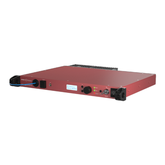
Figure 1 ADJUSTIK front panel Figure 2 ADJUSTIK HP front panel The ADJUSTIK and the ADJUSTIK HP are characterized by their output power as either standard or high output power respectively. Operationally the two models are identical and each is available in four variants with additional options that can be specified. -
Page 24: Features And Options
ON to OFF to ON positions to permit a restart (enable) of the laser’s emission. High power variants High power ADJUSTIK HP variants extend the output power of the laser up to 2W. Refer to Table 1 to compare output powers across variants. -
Page 25: Theory Of Operation
Safety Theory of operation The Koheras ADJUSTIK and ADJUSTIK HP are fiber lasers that use a fiber Bragg grating cavity to produce a single mode laser output. The center wavelength of the laser is configurable using either thermal substrate control or optional Piezo components. -
Page 26: Module Variants
Safety Module variants Both the Koheras ADJUSTIK and ADJUSTIK HP are available in four variants. The variants are in general, classified by their wavelength, and output power. Table 1 describes the primary technical differences between the variants showing the typical parameter values. -
Page 27: Tuning Types
The lasers are fitted with Piezo tuning by default. If Piezo tuning is not re- quired, it must be specified when ordering the laser. Output power tuning Output power tuning is determined by the ADJUSTIK variant type: • C15 and Y10 variants – No power tuning, output power is fixed at the factory. -
Page 28: Front And Rear Panels
Safety Front and rear panels Front panel Figure 3 shows the front panel of the laser. On the front panel are two optical outputs, main and monitor. The front panel also includes controls to turn on and operate the laser autonomously without using CONTROL software. The controls include: •... -
Page 29: Rear Panel
If no accessories are connected, the supplied bus defeater must always be placed on the External bus connector to loop back the interlock safety circuit – see “Connecting the safety interlock” on page The ADJUSTIK controls and panel layout are identical... -
Page 30: Optical Specifications
Appendix C Optical specifications Main optical output ADJUSTIK lasers are classified as laser CLASS 3B and ADJUSTIK HP lasers as CLASS 4. The main optical output is identified by the laser aperture label placed next to it. See “Chassis labels” on page... -
Page 31: External Cavity Stabilization
Laser features Input circuits Section “Fast wavelength modulation” on page 39 provides examples of fast wavelength modulation circuits and performance. Wavelength+/- Signal To modulate the laser’s wavelength, you can apply an external differential signal to the modulation connector pins on the rear panel. As the input signal varies and increases its positive potential, the wavelength of the laser increases. -
Page 32: Trigger
Better Power Stability Better Frequency Stability E15 & X15 Better Performance Not Recommended Both ADJUSTIK & ADJUSTIK HP Note: Variants that support both modes are configured from the factory to operate in Power mode by default. Note: To set the operating mode, see “Power /current mode”... -
Page 33: Optical Interface
~10 microns Numerical aperture 0.14 0.12 0.125 Mode field diameter is approximate - contact NKT Photonics Support for more Support contact details on page 110 information – see Example specifications listed are design intent and are subject to change. Support... -
Page 34: Laser Control
User interface The laser and any associated accessories are controlled either from a PC using NKT Photonics CONTROL management software or the front panel interface. As an option, the laser can also be controlled using NKTP’s Software Development Kit (SDK) for custom applications. For further information regarding the SDK refer to the software and drivers link at NKTP’s support webpage:... -
Page 35: Status Leds
O NOT OPERATE taken all precautions necessary as described in the document: Koheras ADJUS- TIK Safety, Handling and Regulatory Information or Koheras ADJUSTIK HP Safe- ty, Handling and Regulatory Information. -
Page 36: Chassis Labels
Laser features Chassis labels The laser chassis has a number of labels on it that indicate hazards, regulatory, or manufacturing information. The labels are located on the panels described in Table 5 with the panels shown in Figure 5 Figure Figure 5 Top panel label locations Figure 6 Rear panel label location... -
Page 37: Table 5 Module Labels
DANGER - INVISIBLE LASER RADIATION Hazards rating. AVOID EYE OR SKIN EXPOSURE TO Koheras DIRECT OR SCATTERED RADIATION CLASS 4 LASER PRODUCT ADJUSTIK HP Manufacturing Rear Manufacturing information including address, part and serial number, date manufactured and regulatory compliance. Product... - Page 38 Laser features...
-
Page 39: Modulation
Wavelength modulation must be specified when ordering the laser. Note: An E15 ADJUSTIK variant is capable to decrease output power down to 30% of the nominal level. However, the laser’s performance will vary depending on the level of the output power set. Therefore, the E15’s performance is only guaranteed at the nominal (maximum) output power setting. -
Page 40: Wavelength+/- Signal
Fast wavelength modulation Table 6 Wavelength modulation settings Setting Function For CONTROL see For SDK see External wavelength Sets wavelength page 75 page 84 modulation modulation to external signal mode. Internal function Sets wavelength page 77 page 84 generator modulation to internal function generator mode. -
Page 41: Differential Input
Fast wavelength modulation Differential input When configured as an input, the Wavelength+/- input can be connected to a differential signal with an amplitude up to 2x 5 Vpp as shown in Figure Figure 7 Differential input signal graph for wavelength modulation Note: To prevent noise being induced that could create undesired phase noise, it is recommended to disable the wavelength modulation setting when it is not in... -
Page 42: Figure 9 Single-Ended Input Signal With 2.5 V Graph
Fast wavelength modulation 2.5 V or AGND. A single-ended 5 Vpp signal generates half the modulation compared to a differential 2x5 Vpp input. Figure 9 Single-ended input signal with 2.5 V graph Figure 10 shows the Wavelength- pin connected to the same potential as the common mode voltage of the Wavelength+ signal, the optical output will be modulated around its center wavelength. -
Page 43: Wavelength- To Agnd
Fast wavelength modulation Wavelength- to Figure 12, the Wavelength- signal is connected to AGND and the Wavelength+ signal is modulated between 0 and 5 V as shown in Figure 11, the optical output AGND is modulated above its thermally controlled wavelength. Figure 11 Single-ended input signal with GND on an unused branch graph Figure 12 Single-ended input connections with 0 V on an unused branch... -
Page 44: Differential Output
Figure 13 Differential output signal graph The differential output signal can be used for example, as the input signal for other Koheras ADJUSTIK or ADJUSTIK HP lasers. Wavelength You can select either internal AC or DC coupling of the modulation signal. If AC coupling is chosen, the laser’s high pass filter function has a cut-off frequency of... -
Page 45: Frequency Response
Fast wavelength modulation Frequency For X15 variants, the frequency response of the wavelength modulation feature differs from that of the E15/C15/Y10 variants. The graphs in Figure 14 (X15) and response Figure 15 (E15/C15/Y10) shows the response when the modulation signal varies from 1 to 100 kHz. -
Page 46: Amplitude Modulation
Amplitude modulation • Narrow – 10x (times) less with a 3 dB cut-off at 1 kHz Figure 15 E15/C15/Y10 variant wavelength modulation response graph Amplitude modulation If the laser includes the amplitude modulation option, the output emission power level can be modulated. The power amplitude can be modulated with either an electrical input signal or the built-in function generator. -
Page 47: External Cavity Stabilization
Amplitude modulation when the summation exceeds 0V and reaches its maximum (the power setpoint) +5 V separation. Figure 16 Differential input for amplitude modulation graph • Alternatively, Figure 17 shows the Amplitude+/- negative pin connected to ground with the positive branch connected to a signal that varies between 0 V and +5 V. -
Page 48: Setting Up External Cavity Stabilization
Amplitude modulation general layout of the devices in a Pound-Drever-Hall configuration used with the laser. Figure 18 Koheras ADJUSTIK in a Pound-Drever-Hall configuration Setting up external Follow the steps below to configure and enable external cavity locking: cavity stabilization 1. Enable external modulation (see “Modulation Source”... -
Page 49: Operating The Laser
SECTION 2 OPERATING THE LASER This section describes how to manage and operate the laser and includes the chapters: • “Front Panel Menu” on page 51 • “Communicating with the Laser” on page 59 • “Turning ON the Laser” on page 63 •... -
Page 51: Front Panel Menu
Front Panel Menu Overview The front panel features an LCD system menu and controls you can use to configure and operate the laser. The menu items available are listed in Table Table 8 Front panel menu items Menu Item Function Top menu Displays the wavelength, output power and Top menu on page 52... -
Page 52: Menu Items
Menu items • Navigate to sub-menu’s from the top level. • Adjust parameter values when they are selected using the enter button. Emission button - see “Emission button” on page 57 Press this button to: • Enable laser emission. • Disable laser emission. -
Page 53: Wavelength
Menu items Wavelength You can change the center wavelength of the laser emission using the Wavelength menu shown in Figure 20. You can set the center wavelength either as an absolute wavelength or configure a relative offset from the nominal wavelength. -
Page 54: W1 Mod. Gain
Menu items W1 mod. Gain Use the W1 mod. Gain menu to adjust the gain of the signal used to modulate the wavelength. Enter the menu and adjust the gain from 0 to 242.5%. Figure 23 Wavelength modulation gain setting menu W1 mod. -
Page 55: W1 Mod. Range
Figure 27 Operation mode set to constant power mode Power Use the Power menu to tune the level of the laser’s output emission power. The maximum output power level for the ADJUSTIK is dependent on the laser variant. Refer to power specifications listed in Table... -
Page 56: Power Unit
Menu items Power unit You can set the output power to be displayed in either milliwatts (mW) or decibel- milliwatts (dBm). Select this Power unit submenu and turn the selection dial left or right to set the power units to either mW or dBm. Figure 29 Power unit menu - set to mW Watchdog timer If the communications link between the laser and the CONTROL GUI on a PC is... -
Page 57: Ip Address
Turning on the laser will emit hazardous laser Class 3B or Class 4 radi- ation. Ensure to observe and implement all safety regulations, warnings and cau- tions in this guide and in either the Koheras ADJUSTIK Safety, Handling and Regulatory Information or Koheras ADJUSTIK HP Safety, Handling and Regulato- ry Information document before continuing. - Page 58 Menu items...
-
Page 59: Communicating With The Laser
CONTROL communications to the laser using either an USB or Ethernet connection. CONTROL software The laser is shipped with the NKT Photonics CONTROL software installer on a USB key. You can also download the most recent CONTROL software from the following link: https://www.nktphotonics.com/lasers-fibers/support/software-drivers/... -
Page 60: Ethernet Connection
Connecting the laser to a CONTROL PC Action Launch the CONTROL software by either: • clicking on Windows – Start – Programs – NKT Photonics –CONTROL – or – • double clicking the CONTROL shortcut on the desktop The CONTROL window opens. -
Page 61: Procedure 2 Connecting A Pc To The Laser Using Ethernet
Connecting the laser to a CONTROL PC Procedure 2 Connecting a PC to the laser using Ethernet Action Configure the ADJUSTIK IP address using either CONTROL connected over USB (Ethernet on page 80 or the front panel controls (IP Address on page 57). - Page 62 Connecting the laser to a CONTROL PC Action Click the Save button to save the configuration of the new Ethernet connection. To delete or modify a configured port: Delete button 1. Highlight the port and click the delete button - or - Edit button 2.
-
Page 63: Turning On The Laser
Turning on the laser emits hazardous laser Class 3B or Class 4 radiation. Ensure to observe and implement all safety regulations, warnings and cautions in this guide and the Koheras ADJUSTIK Safety, Handling and Regulatory Informa- tion document before continuing. -
Page 64: Back Reflection
Enabling and disabling emission Caution: Do not turn on the laser if it has been exposed to temperature and hu- midity beyond the operating specifications. The laser is designed to operate in a non-condensing environment from +15°C to +60°C. Before turning on the laser, al- low it at least 30 minutes to stabilize at the operating room temperature. - Page 65 Enabling and disabling emission Action 3 Turn the key switch on the front panel to the ON position. NOTE: If the key switch is set ON and the interlock LED on the front panel is still amber, turn the key back to OFF and then ON again. This resets the interlock as long as the interlock circuit is closed.
-
Page 66: Enable Emission (Front Panel)
Enabling and disabling emission Action 7 To disable emission – click the Emission ON/ OFF button once. Click Emission to turn OFF the laser Enable emission To turn on the laser using the front panel controls follow the steps in (front panel) Procedure Note:... - Page 67 Enabling and disabling emission Action 3 If the Key switch off message is displayed – go to step 4. Front panel key switch is in the OFF position 4 Turn the key switch on the front panel to the ON position. 5 The Laser off message indicates laser emission can be enabled.
- Page 68 Enabling and disabling emission Action 7 Interlock opened message – this message is displayed if there is a break anywhere in the interlock circuit. Emission is disabled and the status LED on the front panel is lit ON Red. Connecting the safety interlock on page 97 for further information.
-
Page 69: Using Control
Using CONTROL CONTROL overview The CONTROL interface includes multiple panels and a selection of menu drop down items in the upper left corner. Using the Window drop down menu, you can add or remove the displayed panels and panels can be dragged within the main window or into separate windows. -
Page 70: Relocating Panels
CONTROL overview Relocating panels You can drag the different panels of CONTROL to any location within the main interface or into a separate floating panel. Procedure 5 describes how to relocate a panel within the main window. Procedure 5 Relocating panels Action Left click and hold the top title bar of the panel. -
Page 71: Toggling Panels Visible
CONTROL overview Toggling panels Use the Menu > Window drop down menu to check and uncheck panels to be displayed. A blue check mark indicates the panel is displayed. visible Figure 36 Toggling panel visibility Check the panels to display them Note: To close a panel, click the X at the upper right corner of the panel. -
Page 72: Device Selector
The Device Selector panel shows an icon for each connected device. Figure 39 shows the device selector for an ADJUSTIK laser. If multiple lasers are detected by CONTROL, click on the ADJUSTIK icon to brings up its controls. To modify the ICON text, see“View” on page... -
Page 73: Status Panel
CONTROL overview Status panel The Status Panel provides status indicators, error messages, an emission control function and a settings drop down menu. Figure 40 Status panel Click Status indicators The panel includes the following indicators: Interlock Indicates the status of the interlock circuit. •... -
Page 74: System Info
CONTROL overview • ON Amber – The laser is in the process of warming up or a system error is detected. System info The System Info section shows the following: • Laser serial number • Laser firmware version Measurements Displays the system temperature. WL mod button and Button indicator... -
Page 75: Control Settings
CONTROL overview CONTROL settings The GUI settings are accessible by clicking the gear icon in the upper right corner of the status panel. Clicking the gear icon, drops down a menu of setting items as shown in Figure Figure 41 GUI settings Click the gear icon to access the menu Function... -
Page 76: Figure 42 Wavelength Modulation - Internal Source
CONTROL overview • Internal (Figure 42) – the wavelength is modulated by the internal function generator signal. • External (Figure 43) – the wavelength is modulated by a signal connected to the Wavelength+/- pins. You can connect an external modulation signal to either the laser’s interface board connectors as described in “Connecting modulation signals”... -
Page 77: Figure 44 Internal Generator Waveform Selection - Type
CONTROL overview Modulation Type (internal mode) If the Modulation source is set to Internal, you can set the signal waveform type that is generated internally. Click the Type drop-down menu arrow and select either Sinusoidal, Triangle, Sawtooth or an Inverse sawtooth waveform. Figure 44 Internal generator waveform selection –... -
Page 78: Amplitude Modulation
CONTROL overview 3. All other lasers operate in slave mode by setting them to External modulation mode. Internal generator Frequency When the modulation source is set to Internal, you can adjust the frequency of the internal generator signal to between 8 MHz (0.008 Hz) and 100 kHz (100,000 Hz). -
Page 79: Figure 46 Amplitude Modulation Source Settings
CONTROL overview – see “Amplitude modulation” on page 46 “Interface Pin Assignments” on page 111. To use the internal generator, see “Internal generator” on page Figure 46 Amplitude modulation source settings... -
Page 80: Ethernet
CONTROL overview Internal generator To modulate the output power using an internal generator, set the amplitude modulation source to Internal. Figure 47 shows the internal generator settings. Figure 47 Internal generator amplitude modulation settings Type – Select the modulation waveform type: Sinusoidal, Triangle, Sawtooth, or Inverse Sawtooth. -
Page 81: Watchdog
CONTROL overview same port for transmission as for reception (i.e. as configured under the System port). Default setting is 0. If Local port in CONTROL’s Ethernet connection is configured differently than the Remote port, the CONTROL computer’s port should match the Remote port. MAC Address The MAC address for the laser’s Ethernet frames is shown in the bottom of the Ethernet settings. -
Page 82: Clock
CONTROL overview Clock Within the Clock setting menu, you can update the system date and time from the connected PC. Date Displays the system date in the format DD/MM/YYYY. Time Displays the system time in 24 hour format: HH:MM:SS. Set to computer clock Click the Set button to update the system time and date from the connected PC’s current time and date setting. -
Page 83: Control Menu Items
Procedure 6 Using the Key Updater tool Action Enter a key code in the field “Enter key code”. NOTE: Key codes are generated by NKT Photonics. In the list of modules, check the box on the right of each applicable module. -
Page 84: Log Downloader
Photonics support personnel. Log Downloader If your laser requires support from NKT Photonics, our support engineers may request you send them log files collected by the laser. You can use the log downloader tool to save laser log files to your CONTROL PC. -
Page 85: Extensions Overview
Use this tool to view the installed extensions (similar to plugins) that are included Overview with CONTROL. The extensions are found in the following folder: C:\Program Files (x86)\NKT Photonics\NKTP CONTROL\Plugins To view the extensions, open the Tools menu and click on Extensions Overview. The Extensions Overview window is launched as shown in... -
Page 86: Figure 53 Extensions Overview
CONTROL menu items Figure 53 Extensions Overview Note: To show a short description of the release notes as seen in Figure 53, hover the mouse pointer over the “Release notes” text The Pub*****Lib.dll details highlighted in Figure 53 shows the version of the .dll file (x.x.x.xxx ), the included extensions and which module types they support. -
Page 87: Control - Control Panel
Note: The range of the power control varies and depends on the power capabili- ty of the ADJUSTIK or ADJUSTIK HP. Current mode When set to Current operating mode, the current in the fiber pump is kept at a constant level. -
Page 88: Device Monitor
CONTROL menu items Device monitor The device monitor provides a live display of transmit and receive parameters of the laser’s communication ports and any connected device modules. The display parameter values are continuously updated and can be used to help debug communication issues with connected devices. -
Page 89: Application Log
Application log Parameter Description Total number of communication errors with framing or protocol errors. Hover over the icon to list more details. Busy Total number of busy responses from the module. Busy responses occur when a module receives a message but cannot process it due to its current work load. - Page 90 Application log...
-
Page 91: Installing The Laser
SECTION 3 INSTALLING THE LASER This section provides information on how to install the laser and includes the chapters: • “Mechanical Installation” on page 93 • “Connecting the Laser” on page 97... -
Page 93: Mechanical Installation
Ensure that the installation space provides adequate airflow in the vicinity of the rear panel heat sink. Caution: For ADJUSTIK HP variants, heat dissipation is vital, ensure the laser’s operating temperatures are maintained. Figure 56 Rear panel heat sink... -
Page 94: Placing The Laser On A Table Or Shelf
Figure 59 shows the laser placed on a solid table-top with no nearby heat sources and with adequate free-space for the cooling fins. Caution: For ADJUSTIK HP variants, heat dissipation is vital, ensure the... -
Page 95: Figure 58 Rubber Mounting Feet
Placing the laser on a table or shelf laser’s operating temperatures are maintained. Figure 58 Rubber mounting feet Rubber fee Figure 59 Table or shelf mounting... -
Page 96: Operating And Storage Environment
Warning: A Koheras ADJUSTIK laser is either a Class 3B or Class 4 laser product, and its operation facility and environmental conditions must comply with the stan- dards listed below or similar: •... -
Page 97: Connecting The Laser
Figure 60 Interlock connected to a door switch - Laser ON Bus Defeater Accessory Control unit key switch LEMO Connector Energized Door External Bus Switch Connector Logic Circuit Normally Open Interlock Monitor Koheras ADJUSTIK Reset Laser Control Circuitry Shutdown Laser... -
Page 98: Interlock Alarm
Caution: Do not short-circuit the Interlock input. Short-circuiting the interlock cir- cumvents safety regulations and NKT Photonics does not take liability for any in- juries or damage caused by doing so. Caution: The switch connected to the interlock must be of an approved type. -
Page 99: Bus Defeater
Connecting power Procedure 8 Connecting the door interlock circuit Action Install a switch that opens when the door accessing the laser installation enclosure is opened. The switch must comply with safety regulations. Using a cable with a maximum wire length of five meters and at a minimum 26 AWG, connect the switch to a LEMO connector. -
Page 100: Connecting Modulation Signals
Connecting modulation signals Table 11 Power specifications Item Description AC Mains 100-240 VAC @ 50-60 Hz Input Power cord The power cord must be capable to safely transmit the laser’s specified AC ratings while maintaining a safe connection with the local AC mains outlets. The power cord used must follow local or national regulations. -
Page 101: Output Trigger
Using the microscope, check for any de- formities, damage, residue or other contaminants at the optical tip of the connec- tor. Either clean the connector or contact NKT Photonics support if a replacement is necessary. -
Page 102: Cleaning Of Fiber Facets
Cleaning of fiber facets The facets of the system fiber connectors may occasionally require cleaning. Particularly for ADJUSTIK HP variants, as any contaminants might be susceptible to the system’s higher output power. Before making any fiber connections, always inspect the fiber facet of all connectors using an inspection scope. A scope with both coaxial and oblique illumination is useful in exposing any contaminants or defects in the facet. -
Page 103: Appendices
APPENDICES The appendices include: Appendix A on page 105 Specifications • Appendix B on page 109 Service and Support • Appendix C on page 111 Interface Pin Assignments • Appendix D on page 113 CONTROL Installation • Appendix E on page 119 Part Numbers •... -
Page 105: A Specifications
Specifications Table 12 Koheras ADJUSTIK optical specifications CW - inherently single frequency Laser Emission > 10 > 10 Output power (mW) < 1.05 < 1.05 < 1.05 < 1.05 Beam Quality (M2) < 0.1 < 0.1 < 15 < 20... -
Page 106: Table 13 Koheras Adjustik Hp Optical Specifications
Table 13 Koheras ADJUSTIK HP optical specifications CW - inherently single frequency Laser Emission 0.2 / 2.0 0.2 / 2.0 0.2 / 2.0 Output power (W) 1545-1565 1545-1565 1545-1565 1060-1075 Operating wavelength 10-100 10-100 10-100 10-100 Output power tuneability (%) <... -
Page 107: Table 17 Safety And Regulatory Compliances
Table 17 Safety and regulatory compliances Safety Regulatory EN 60825-1:2014: Safety of laser products EN 61326-1:2013: Electrical equipment for measurement, Part 1: Equipment classification and requirements control and laboratory use EMC requirements – Part 1: General requirements [Laser Class 4] 2004/108/EC Electromagnetic Compatibility EN 61010-1:2010:Safety requirements for electrical 2011/65/EC Restriction of the use of certain Hazardous... -
Page 109: B Service And Support Information
Service and Support Information Servicing the laser The laser have no user serviceable components. In case of malfunction, contact NKT Photonics using the support channels in section “Support contact details”. Do not open the laser’s modules. The laser modules are equipped with warran-... -
Page 110: Support Contact Details
Servicing the laser Support contact details If you need help or have questions regarding your Koheras ADJUSTIK laser or its accessories, contact NKT Photonics through our support website below: Support website 1. Go to: https://www.nktphotonics.com/lasers-fibers/support/technical-support-and- customer-service/ 2. Scroll down and click or press: 3. -
Page 111: C Interface Pin Assignments
Emission Collector output with an internal 270 Ω resistor in series. Outputs a logic high when the Koheras ADJUSTIK system has laser emission ON. To indicate emission with an LED, its anode can be connected directly to this pin and its cathode connected to the GND (pins 5,6, 13 or 14). - Page 112 External bus Pin # Signal Description Interlock Logic Outputs a logic high (5V) when the interlock circuit is closed and has Output been reset. This signal can be used to control safety related precautions on the External Bus. 5,6,13,14 0 volt ground. 7,8,15 +12 V 12 volt supply voltage for external accessories.
-
Page 113: Dcontrol Software
CONTROL Software Installing CONTROL Download the software from: https://www.nktphotonics.com/lasers-fibers/support/software-drivers/ Follow the steps in Procedure Procedure 9 Installing CONTROL Action On the PC, launch the installer package and then click the Installer Run button. The installation wizard appears. Click Next to continue. Accept to use the default installation directory or select another directory by clicking the Browse button. - Page 114 Installing CONTROL Action Uncheck the components you do not require. By default, all components are installed. Click Next to continue. Read the End-User License Agreement, and check “I accept the license.” box. Not checking the box ends the installation wizard. Click Next to continue.
- Page 115 Installing CONTROL Action Check the box to create a desktop shortcut to access Control. Click Next to continue Check the ‘Run the Silicon Labs CP10x driver installation’ box and click Next. Note: If you do not have the driver installed USB connectivity will fail.
- Page 116 Installing CONTROL Action The wizard displays a progress meter for the installation. Note: a normal install should only take a few seconds. Click Next to install the UART drivers for the PC USB port.
- Page 117 Installing CONTROL Action The drivers are installed. Note: Depending on your computer this occurs so fast you may not see this. The Silicon Labs drivers is installed successfully. Click Finish to end the driver installation. CONTROL is now installed. Check the Run box to launch CONTROL when the Finish button is clicked.
- Page 118 Installing CONTROL...
-
Page 119: E Part Numbers
Part Numbers ADJUSTIK and ADJUSTIK HP lasers variants are listed by their part numbers in the table below Table 21 ADJUSTIK and ADJUSTIK HP part numbers Name Laser module Output power Part number Koheras ADJUSTIK K8222 40 mW Koheras ADJUSTIK K8221 >... - Page 122 Item 800-611-01 Koheras ADJUSTIK Product Guide Revision 1.1 03-2022 W-10456...
Need help?
Do you have a question about the ADJUSTIK and is the answer not in the manual?
Questions and answers