Table of Contents
Advertisement
Quick Links
Advertisement
Table of Contents

Related Manuals for NKT Photonics SuperK Extreme


Summary of Contents for NKT Photonics SuperK Extreme
- Page 1 SUPERK EXTREME White Light Laser PRODUCT GUIDE...
- Page 2 This guide includes the following NKT Photonics Lasers: SuperK Extreme Supercontinuum White Light Laser with optional Variable Repetition Rate SuperK Extreme OCT Supercontinuum White Light Laser with Low Noise Output for Optical Coherence Tomography SuperK Extreme Product Guide Revision 1.0 12-2019 W-10456...
-
Page 3: Guide Overview
GUIDE OVERVIEW This product guide is intended to provide functional, operational and installation information for the SuperK Extreme laser systems. The guide is divided into three sections: • SuperK Extreme Description – introduces the laser’s theory and functionality, its features and interfaces, and describes the safety labels and their placement. - Page 4 • Chapter 7 “Connecting the Laser” — This chapter provides the information on how to physically connect the safety interlock, power, the optical collimator, and the synchronization interfaces. • Appendices — The guide includes multiple appendices including laser specifications, support contact details, accessory descriptions and miscellaneous procedures supporting the laser operation and installation.
-
Page 5: Table Of Contents
CONTENTS Guide overview ........................3 TABLES ........................11 FIGURES ........................13 PROCEDURES ......................17 Section 1 SUPERK EXTREME DESCRIPTION 1 Laser description ........................21 Terminology ......................21 Accessories ......................22 CONTROL ......................22 Temperature regulation ..................22 Optical output ......................22 Supercontinuum ....................22 Spectral output .................... - Page 6 Operation dial ...................... 27 Power LED ......................27 Emission LED ....................... 27 Emission button ....................27 Key switch ......................27 Rear panel interfaces ....................28 Output Control ..................... 28 Seed Pulse output ....................29 Post VRR synchronization interfaces ............. 29 Modulation input ....................
- Page 7 Status display ......................41 Date and time ...................... 42 Display contrast ....................43 Display backlight ....................43 Serial numbers .....................44 Firmware versions ....................44 Emission button ......................45 3 Connecting and turning ON the laser ................47 CONTROL software ....................47 Installing the software ..................47 Connecting the laser to a CONTROL PC ............47 USB connection ....................47 Controlling the laser emissions ................
- Page 8 Log Downloader ....................61 Extensions overview ..................63 CONTROL – Operating mode ................64 Variable Repetition Rate (Pulse Picker) ............64 Application Log panel ..................... 65 Device Monitor ......................66 5 Configuring External Control ..................69 External Feedback ....................69 Output Control ......................
- Page 9 NIM Pulse ......................86 Appendices A Specifications ........................91 B Service and Support Information ..................93 Servicing the laser ....................93 Opening the laser chassis ................93 WARRANTY VOID IF REMOVED label ............93 Support contact details ................... 93 Support email ...................... 93 Online support web-page ................
-
Page 11: Tables
Table 16: Interfaces ......................91 Table 17: Mechanical dimensions ..................92 Table 18: Electrical........................ 92 Table 19: SuperK Extreme accessories ................. 95 Table 20: Varia specifications................... 96 Table 21: Select AOTF types ..................... 98 Table 22: LLTF Contrast Model Specifications............. 99 Table 23: SPLIT Wavelength ranges ................100... -
Page 13: Figures
Figure 7: Seed Pulse output ..................... 29 Figure 8: NIM pulse output ....................30 Figure 9: Pulse monitor output ..................30 Figure 10: SuperK Extreme rear panel status LEDs ............ 33 Figure 11: SuperK Extreme Panels ................... 34 Figure 12: Constant current level adjustment .............. 38 Figure 13: Interlock circuit open notification .............. - Page 14 Figure 40: Application Log window ................66 Figure 41: Output Control trigger vs optical output rise ..........70 Figure 42: SuperK Extreme installation ................. 76 Figure 43: Interlock connected to a door switch - Laser ON ........78 Figure 44: Interlock connected to a door switch - Laser SHUTDOWN ....79 Figure 45: Inserting the Collimator into a Holder ............
- Page 15 white...
-
Page 17: Procedures
PROCEDURES Procedure 1: Connecting a PC to the laser using a USB cable ....... 48 Procedure 2: Turning on the laser .................. 50 Procedure 3: Turning off the laser ................... 51 Procedure 4: Relocating panels ..................54 Procedure 5: Using the Key Updater tool..............61 Procedure 6: Using the Log Downloader .............. -
Page 19: Superk Extreme Description
SECTION 1 SUPERK EXTREME DESCRIPTION This section provides a description of the laser and its features. “Laser description” on page 21 • “Optical output” on page 22 • “Reflection monitor” on page 26 • “Front panel controls” on page 26 •... -
Page 21: Laser Description
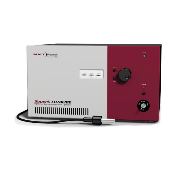
Laser description SuperK Extreme lasers are a series of white light lasers (WLL) systems that can generate a pulsed supercontinuum as a class 4 laser source. Using a 78 Mhz seed laser, light frequencies from 400 to 2400 nanometers (typical) are emitted in a single spatially coherent beam with a pulse rate that is customizable according to application requirements. -
Page 22: Accessories
Accordingly, the width of the spectral output increases with the output power. Spectral output Figure 2 below shows the output spectrum of a SuperK EXTREME at output power levels of: A. 4.5 W B. 2.8 W C. -
Page 23: Collimator
The collimated beam exits the collimator from a hollow steel sleeve which is inserted into a receptacle of a target optical device such as for example, a SuperK accessory or an optical power meter. Figure 3 SuperK Extreme collimator Output Aperture 12 mm 3.5 mm... -
Page 24: Beam Diameter
1.94 mm Factory test report The SuperK EXTREME laser systems can be specified in multiple configurations with different spectral- and power performance. The system performance of each laser is described in factory created test- and measurement report. Refer to this report for the spectral performance of the individual SuperK EXTREME system. -
Page 25: Variable Repetition Rate (Pulse Picker)
1:14 Note: Other possible configurations of repetition rates may be available depend- ing on the laser’s specifications. Contact NKT Photonics for further information. Using VRR If the repetition rate is changed while the system has emission on, the system momentarily shuts off emission, changes the repetition rate and turns on emission again. -
Page 26: Reflection Monitor
Reflection monitor Reflection monitor The SuperK EXTREME is equipped with a reflection monitor to avoid damage from back reflections that can destroy the system. When the reflection monitor detects a back reflection that exceeds the limit, the laser shuts down and displays the error code: “Code 48, 5 0x65”. -
Page 27: Operation Lcd Panel
Front panel controls Operation LCD The LCD panel displays a menu system used for front panel operation of the panel laser along with the operation dial and return/enter buttons. The menu system shown on the display can configure, operate and view the laser status. Return button The button confirms and enters settings made with the operation dial Enter button... -
Page 28: Rear Panel Interfaces
Rear panel interfaces Rear panel interfaces The rear panel houses the electrical ports and status LEDs. The panel and its components are depicted in Figure Figure 6 Rear panel features and connectors 13 14 Collimator and Armored Cable Assembly AC Power connector and power switch Collimator Storage Receptacle 10 External Bus - DB-15 connector NIM Pulse –... -
Page 29: Seed Pulse Output
Rear panel interfaces Maximizing the laser warranty The laser’s lifetime is influenced by the total usage of the main amplifier. When the application does not require the laser to be ON continuously. Laser lifetime can be optimized by minimizing the laser ON time. When this feature turns off the laser booster, the laser seed is still Warning: ON and low level Class 4 emission is still present at the laser aperture. -
Page 30: Figure 8 Nim Pulse Output
Rear panel interfaces Figure 8 NIM pulse output Pulse Monitor This signal represents the laser pulse output after the VRR module. The signal is intended for applications that require a positive bias synchronization signal for external devices. Its output level ranges from 0 to +1.2 V (approximately). For further information See “Connecting synchronization ports”... -
Page 31: Modulation Input
Configuration and operation overview Modulation input A standard SuperK EXTREME laser features two operating modes: Current mode and Power mode. SuperK Extreme lasers equipped with the Modulation Input option can operate in two additional modes: • Modulated Current – sets a maximum CURRENT value (set point) and CURRENT in the laser booster is modulated by a signal voltage applied to the Modulation input connector. -
Page 32: Advanced Laser Control
OFF position and back to the ON position. Only after the key is cycled, the interlock is reset and emissions are permitted. Laser accessory The External Bus (6) port connects optional SuperK Extreme accessories. The management port provides a bus control interface and 12V DC power to optional smart accessories. -
Page 33: Status Leds
PC. No transmitted data detected Note: the laser until you are familiar with the controls and have O NOT OPERATE taken all precautions necessary as described in the SuperK Extreme Safety, Han- dling and Regulatory Information document. Laser description... -
Page 34: Chassis Labels
Chassis labels Chassis labels The SuperK Extreme chassis includes multiple labels that indicate hazards and regulatory or manufacturing information. The labels are located on the rear panel, the armored fiber cable, and the collimator as described in Table 4. Label... -
Page 35: Operating The Laser
SECTION 2 OPERATING THE LASER This section describes how to manage and operate the laser and includes the chapters: • “Front Panel Controls” on page 37 • “Connecting and turning ON the laser” on page 47 • “Turning on the Laser” on page 53 •... -
Page 37: Front Panel Controls
Front Panel Controls Overview The front panel features an LCD system menu and controls that can be used to configure and operate the laser. The menu items available are listed in Table Table 5 Front panel menu items Menu Item Function Output Sets the output level of the laser by adjusting... -
Page 38: Menu Items
Menu items Exit menus Press the return button to exit a sub-menu and return to the parent menu. To turn off the panel, press the return button while in the top menu. Menu items Output emission The operation dial can also be used to adjust the laser output emission level. To control adjust the level: Access the top menu and press the return button - i.e. -
Page 39: Key Switch
Menu items Figure 13 Interlock circuit open notification Key Switch If the laser key switch is set in the OFF position, a notification that the key switch is OFF is displayed. Figure 14 Key switch off notification Note: When the key switch is in the OFF position, laser emission cannot be start- ed. -
Page 40: Repetition Rate
Menu items Note: NKT Photonics offers optional modes that can be added upon request. See “Configuring External Control” on page To set the operating mode: Press the enter button to enter the laser control menus. 2. Turn the operation dial until the menu displays, “System menu - Operating Mode”... -
Page 41: Input Readouts
• User text – a user defined text string (for example the laser’s name; configured with NKT Photonics CONTROL software, see “View” on page • Date and time – the current system date and time, see “Date and time”... -
Page 42: Date And Time
Menu items • A blank line – i.e. no text is selected for display To select and set the status display: Press the enter button to enter the laser control menus. 2. Turn the operation dial until the menu displays, “System menu/Status display”... -
Page 43: Display Contrast
Menu items Display contrast This sub-menu adjusts the LCD panel contrast from 0 to 100%, in steps of 1%. To change the contrast, follow the steps below: Press the enter button to enter the laser control menus. 2. Turn the operation dial until the menu displays, “System menu /Display contrast ”... -
Page 44: Serial Numbers
Menu items Serial numbers Select this sub-menu to view the laser serial numbers. The serial numbers of the laser’s modules and connected accessories are displayed. To display the serial numbers: Press the enter button to enter the laser control menus. 2. -
Page 45: Emission Button
Warning: Turning on the laser will emit hazardous laser Class 4 radiation. Ensure to observe and implement all safety regulations, warnings and cautions in this guide and the SuperK Extreme Safety, Handling and Regulatory Information doc- ument before continuing. Caution: Do not turn on the laser if it has been exposed to temperature and hu- midity beyond the operating specifications. - Page 46 Emission button Front Panel Controls...
-
Page 47: Connecting And Turning On The Laser
Connecting and turning ON the laser The SuperK Extreme laser can be managed using NKTP CONTROL software installed on a PC. This chapter focuses on: • How to obtain and install the CONTROL software • Connect a PC using USB connectivity •... -
Page 48: Procedure 1 Connecting A Pc To The Laser Using A Usb Cable
If necessary, wait for the Windows device manager to install the USB drivers for the connection. Launch the CONTROL software by either: • clicking on Windows – Start – Programs – NKT Photonics –CONTROL – or – • double clicking the CONTROL shortcut on the desktop The CONTROL window opens. -
Page 49: Controlling The Laser Emissions
Do not turn on the laser if it has been exposed to temperature and humidity be- yond the operating specifications. The SuperK Extreme is designed to operated in a non- condensing environment from +18 to +30°C (or 35°C). Before turning on the laser, allow it at least 30 minutes to reach room temperature. -
Page 50: Errors
Controlling the laser emissions Procedure 2 Turning on the laser Action On the front panel of the laser, turn the key switch on the laser’s front panel to the ON position. When the key is in the ON position, the laser emissions can be enabled from CONTROL ON position software. -
Page 51: Procedure 3 Turning Off The Laser
Controlling the laser emissions Procedure 3 Turning off the laser Action Turn of the laser emissions by clicking on the software Emission button. The Emission button light turns from RED (ON) to green (OFF). Turn the key switch to the 0 position to disable the laser. - Page 52 Controlling the laser emissions Connecting and turning ON the laser...
-
Page 53: Control Interface
The control panel provides adjustable controls CONTROL – Operating mode for the laser and accessories selected. The on page 64 SuperK Extreme provides configuration controls for current, repetition rate and trigger delay. Application This panel displays a debugging log that can be Application Log panel on saved to a file. -
Page 54: Relocating Panels
CONTROL overview Relocating panels The panels displayed by CONTROL can be dragged to any location within the main interface or into a separate floating panel. Procedure 4 describes how to move a panel: Procedure 4 Relocating panels Action Left Click and hold the top title bar of the panel. While holding the left mouse button down drag the panel to another location in the main window. -
Page 55: Toggling Panels
CONTROL overview Toggling panels Use the Menu > Window drop down menu to check and uncheck panels to be viewed. Figure 28 Toggling panel visibility Check the panels to display them Note: Clicking the X in the upper right corner of any panel will also close it. Connecting to the When CONTROL is launched, the Welcome panel is displayed as in Figure... -
Page 56: Status Panel
Status Panel Status Panel The Status Panel provides status indicators, error messages, emission control function and a CONTROL settings menu. Figure 30 Status Panel Status Indicators The panel displays the following indicators: Interlock Indicates the status of the Interlock circuit and whether emissions can be turned on or not. -
Page 57: System Info
Status Panel • ON RED – There is a fault, laser emissions are shutdown and cannot be turned ON. A fault message will be displayed when this indicator turns ON RED: Fault Message Action Interlock opened while emission on a) Cycle the key switch to OFF and then ON b) Close the external interlock circuit Watchdog timeout Reconnect NKTP CONTROL and reset the interlock... -
Page 58: Control Settings
Status Panel Control settings The CONTROL settings are accessible by clicking the gear icon in the upper right corner of the Status panel. Clicking the gear icon displays a menu of setting items as shown in Figure Figure 31 CONTROL settings Click the gear icon to access the menu Setting Item... -
Page 59: Figure 33 Clock Settings
Status Panel Figure 33 Clock Settings Click to synchronize the CONTROL clock with the PC View The View settings control the display items in the status panel and the front LCD panel: System info – check the box next to “System info” to toggle on displaying the system information within the status panel. -
Page 60: Control Menu
CONTROL menu CONTROL menu There are five drop down menus in the main control window as highlighted in Figure 35. Click on the items in the menu to reveal the drop down menus. Figure 35 Menu items Menu Item Function File Exits the CONTROL program Disconnect... -
Page 61: Log Downloader
NKT Photonics support personnel. Log Downloader If your laser requires support from NKT Photonics, our support engineers may request that you send the log files collected by the laser. You can use the log downloader tool to save the laser log files to your CONTROL PC. -
Page 62: Procedure 6 Using The Log Downloader
CONTROL menu Procedure 6 Using the Log Downloader Action Open the Tools menu and click on Log Download to start the Log Downloader tool. The tool displays all connected modules with log capability. To decrease the download time of the module log files, CONTROL continuously collects module log data and stores this log data in a local database on the... -
Page 63: Extensions Overview
The PubExtremeLib.dll details highlighted in Figure 36 shows the version of the .dll file (1.1.2.303), the included extensions (SuperK Extreme Extension) and which module types they support. Note: Multiple extensions for a wide range of NKTP lasers types are typically in- stalled when using the default installation of CONTROL. -
Page 64: Control - Operating Mode
CONTROL – Operating mode CONTROL – Operating mode For SuperK Extreme the control panel can be configured to present different operating mode controls. Control of the laser emissions varies according to the mode chosen. To select one of the modes listed in... -
Page 65: Application Log Panel
Application Log panel The Application Log panel displays and logs the communication of status messages. The log can be used to debug connection issues between CONTROL and NKT Photonics devices. The panel displays and timestamps the following types of log messages: •... -
Page 66: Device Monitor
Device Monitor The panel includes three buttons in the upper left corner. You can use the buttons to clear, save or print the log. Click on the cross in the upper right corner of the Application Log window to close the Application Log. Figure 40 Application Log window Clear the log Save the log to file... - Page 67 Device Monitor Parameter Description PCB Ver, The version of the device module’s printed circuit board. Sp. Cap/ The module speed capability in bits per second as read from the module – Values: 0=(default) 115200, 1=230400, 2=460800, 3=921600 Pri Ext Primary extension/GUI loaded for this module. Hover over the icon to list more details –...
- Page 68 Device Monitor CONTROL Interface...
-
Page 69: Configuring External Control
Configuring External Control This chapter covers configuration details for: • “External Feedback” – describes how to connect a feedback circuit to the laser to stabilize the output power level. • “Output Control”– describes how to connect an external logic signal to the laser to turn ON or OFF the laser’s booster. -
Page 70: Output Control
Warning: The laser emission is still ON when the booster is OFF; however, resid- ual laser emissions are still produced. Figure 41 Output Control trigger vs optical output rise TTL/CMOS Trigger Output Control Detector SuperK Extreme Configuring External Control... -
Page 71: Modulation Input
Modulated Current and Modulated Power modes. If a voltage higher than 10 volts is applied to the Modulation Input, the voltage across the pull-down resister is clamped and the optical output from the SuperK EXTREME system is limited to the set point value set. -
Page 72: Table 10 Modulation Input - Power Modulation Mode Example
Note: For further information on how to utilize the Modulation Input on the SuperK Extreme, please refer to the NKT Photonics document: Application Note for Using Power Lock and external modulation with the SuperK Extreme You can download the document from link below: https://www.nktphotonics.com/wp-content/uploads/sites/3/2015/05/... -
Page 73: Installing The Laser
SECTION 3 INSTALLING THE LASER This section describes how to install the laser and includes the chapters: • “Mechanical Installation” on page 75 • “Connecting the Laser” on page 77... -
Page 75: Mechanical Installation
Mechanical Installation SuperK Extreme lasers generate a substantial amount of heat that must be dissipated. To dissipate the heat, the SuperK Extreme is available in three different chassis versions defined by their temperature regulation system. This chapter provides information on how to mechanically install the laser with focus on ensuring optimal regulation of the laser’s temperature. -
Page 76: Installing The Laser Chassis
The laser should be located so that the fan intake and exhaust vents are not obstructed. The laser is equipped with four mounting feet and can be placed on any suitable level and stable surface capable of supporting the laser’s weight. Figure 42 SuperK Extreme installation Left Panel RIght Panel... -
Page 77: Connecting The Laser
Connecting the Laser Before operating the laser, follow the procedures in this chapter to ensure its correct and safe operation. For information on how to connect: • the Safety Interlock – see “Connecting the safety interlock” on page 78 • Power –... -
Page 78: Connecting The Safety Interlock
Figure 43 Interlock connected to a door switch - Laser ON Accessory Bus Defeater External Bus Connector SuperK Extreme Energized Door Switch Interlock Connector Logic Circuit... -
Page 79: Figure 44 Interlock Connected To A Door Switch - Laser Shutdown
Shutdown Laser Caution: Do not short-circuit the Interlock input. Short-circuiting the interlock cir- cumvents safety regulations and NKT Photonics does not take liability for any in- juries or damage caused by doing so. Caution: The switch connected to the interlock must be of an approved type. Fur- ther, the switch must be installed in a manner so that its operation cannot be fixed in the open state using a tool to defeat its operation. -
Page 80: Connecting Power
Connecting power LEMO plug The laser is shipped with a prewired 2-pin LEMO interlock plug for inter- connecting the laser with a safety door switch circuit. Procedure 7 Connecting the door interlock circuit Action Install a switch that opens when the door accessing the laser enclosure is opened. The switch must comply with local regulations. -
Page 81: Connecting The Optical Output (Collimator Installation)
Connecting the optical output (collimator installation) Connecting the optical output (collimator installation) Warning: Care should be taken to mount the collimator so that the beam emitted is contained in an area where no personnel or flammable material is present. Back reflection When building and connecting your optical system, you must be careful to avoid creating a path where Back Reflection (BR) can occur. -
Page 82: Connecting Accessories With The External Bus
Connecting Accessories with the External Bus Figure 45 Inserting the Collimator into a Holder Figure 46 Collimator Installed into a SuperK Accessory Receptacle Figure 47 Collimator Installed in a Holder Receptacle Connecting Accessories with the External Bus External Bus The External Bus port is a digital bus interface and 12 volt supply for attached accessories. -
Page 83: Connecting The External Bus
External Bus – External Bus cable – Accessory Input Accessory 1 Output – External Bus cable – Accessory n input Accessory n Output – Bus Defeater Figure 48 External Bus circuit - with no accessories used SuperK Extreme External Bus Connector Bus Defeater... -
Page 84: Connecting Synchronization Ports
Accessory B Connecting synchronization ports The SuperK Extreme can supply up to 4 synchronization signals. The signals can synchronize external devices with the laser pulse at two stages within the laser. If the laser is fitted with a VRR (pulse picker) module, all 4 signals are available. -
Page 85: Terminating Synchronization Signals
Connecting synchronization ports Figure 50 Synchronization ports with output signals Terminating To obtain the best waveform of the signal, connect external devices using the synchronization specifications listed in Table signals Table 14 NIM Pulse connection specification Item Description Cable Type Shielded Coaxial - use RG223 type or similar double shielded cable ... -
Page 86: Seed Pulse
Connecting synchronization ports Figure 51 Example Pulse Circuit Pulsed Emission SuperK Extreme NIM Pulse NIM Level Pulse (post VRR) (RG223 Cable) Synchronizer Sensor Control Subject Target Sensor Output Sensor Seed Pulse The seed pulse is a positive 0 to 0.7 V analog output signal synchronized with the laser seed. -
Page 87: Figure 52 Pulse (Nim) Trigger Delay Control
Connecting synchronization ports Figure 52, set to 8650 picoseconds. In this case, the output pulse will be delayed 8650 picoseconds after the laser pulse. Figure 52 Pulse (NIM) trigger delay control NIM Trigger Delay Slider Connecting the Laser... - Page 88 Connecting synchronization ports Connecting the Laser...
-
Page 89: Appendices
APPENDICES The appendices include: Appendix A on page 91 Specifications • Appendix B on page 93 Service and Support • Appendix C on page 95 Accessories • Appendix D on page 103 Control Software • Appendix E on page 109 Troubleshooting and Errors •... -
Page 91: A Specifications
~2 mm at 1060 nm Typical single mode fiber coupling efficiency > 70% The table provides a general range of values for by the SuperK Extreme lasers. For exact optical specifications, refer to the test report that is shipped with your laser. -
Page 92: Table 17 Mechanical Dimensions
Table 17 Mechanical dimensions 443 x 252.3 x 376.8 mm Size (H x W x D) (3.15 x 7.87 x 14.65 in) 18 kg / 19 kg with VRR Weight option (39.7 lb / 41.8 lb) 18°C to 30°C (59°F to 86°F) Operating Temperature 20 to 80% Operating Humidity (non-condensing) -
Page 93: B Service And Support Information
Service and Support Information Servicing the laser The SuperK Extreme series lasers have no user serviceable components. In case of malfunction, contact NKT Photonics using the support channels in section “Support contact details”. End of line safety tests according to EN61010-1 Annex F are performed on all Laser chassis. - Page 94 Support contact details Service and Support Information...
-
Page 95: C Accessories
This appendix provides a brief overview of the accessories available for your laser. Table 19 lists the accessories and their functions and provides a link to descriptions of the SuperK Extreme advanced accessories. Table 19 SuperK Extreme accessories Advanced accessories Function... -
Page 96: Accessory Descriptions
The Varia accessory acts as a bandpass filter when connected to the collimator of the SuperK Extreme laser. A portion of the beam from the SuperK Extreme is diverted to the Varia’s bandpass filter which removes the light wavelengths that fall outside a variable wavelength range. -
Page 97: Superk Select
Connect, a small aperture is not required; the delivery system aperture will provide the suppression. Output beam specifications AOTF types must be specified when ordering a SuperK Extreme. The type of AOTF determines the possible wavelength range and bandwidth that can be diffracted from the crystal. -
Page 98: Superk Lltf
Accessory descriptions Table 21 Select AOTF types AOTF type Wavelength range (nm) Bandwidth (nm) UV-VIS 400-650 1.8-8.5 VIS (1x) 430-700 0.5-1.85 VIS (4x) 450-700 2.5-8.5 VIS-nIR 500-900 3.5-14 nIR1 640-1100 1,5-5 nIR2 800-1400 2.6-9.6 1100-2000 6.4-19.8 As noted earlier, the tuned beam which is defracted from a Select crystal filter will also include a number of n’th order side lobes. -
Page 99: Superk Split
3.5-14 SuperK Split Use the SuperK SPLIT to divide the SuperK Extreme emissions into two separate spectral outputs. The SPLIT is a passive filter and it is available in two standard models where the spectral outputs are configured as either: •... -
Page 100: Superk Connect
Accessory descriptions Figure 57 SuperK Split Output Aperture Connect Accessory Optical Input SuperK Split specifications Table The specifications of the Split are shown in Table 23 SPLIT Wavelength ranges Model Wavelength Ranges VIR/IR 400-830 and 915-2400 nanometers nIR/IR 400-1120 and 1180-2400 nanometers Note: For further detailed information regarding the SuperK Split refer to the Split Instruction Manual. -
Page 101: Table 24 Fiber Delivery Specifications
Accessory descriptions Figure 58 SuperK Connect Connect specifications The bandpass filter specifications of the Connect are shown in Table Table 24 Fiber delivery specifications Model Single Mode Transmission Typical Peak Cutoff Wavelength Transmission FD1-PM 425±25 nm >60% (425-775 nm) 75% @ 650 nm 450±25 nm >60% (450-775 nm) 80% @ 650 nm... -
Page 102: Superk Extend Uv
Accessory descriptions SuperK Extend UV The Extend UV accessory can extend the laser emissions into the ultraviolet range from 265-480nm. It can output 2 to 12 nm wide collimated pulses down to 20 picoseconds. The output can be coupled into another accessory to tune it for the required application. -
Page 103: D Control Software
Control Software Installing CONTROL Download the software from: https://www.nktphotonics.com/lasers-fibers/support/software-drivers/ Follow the steps in Procedure Procedure 10 Installing CONTROL Action On the PC, launch the installer package and then click the Installer Run button. The installation wizard appears. Click Next to continue. - Page 104 Installing CONTROL Action Accept to use the default installation directory or select another directory by clicking the Browse button. Click Next to continue. Uncheck the components you do not require. By default, all components will be installed. Click Next to continue. Read the End-User License Agreement, and select: “I accept the license.”.
- Page 105 Installing CONTROL Action The wizard will create a start menu folder with program short-cuts. Use the default name or enter a new name for the folder. Click Next to continue. Check the box to create a desktop shortcut to access Control.
- Page 106 Installing CONTROL Action Click Install to install NKTP CONTROL software on your Click Cancel if you want to abort the installation.. The wizard displays a progress meter for the installation. Note: a normal install should only take a few seconds. Click Next to install the UART drivers for the PC USB port.
- Page 107 Installing CONTROL Action The drivers will be installed. The Silicon Labs drivers is installed successfully. Click Finish to end the installation wizard. CONTROL is now installed. Check the Run box to launch CONTROL when the Finish button is clicked. Click Finish. Control Software...
- Page 108 Installing CONTROL Control Software...
-
Page 109: E Troubleshooting And Errors
1. Disconnect the power to the laser. Locate and remove the ground. interlock circuit short to ground. 2. Turn on the SuperK Extreme system and reset the interlock with the key switch. 1. No Power 1. Check the AC Mains and the AC power cable. -
Page 110: Alarms Codes And Recovery
Set to 0% power (slider all the way to the left in Control software) 2. Enable the laser by clicking the Emission button on. 3. Slowly increase power to 100%. If the problem is not resolved contact NKT Photonics. See Appendix Other codes: contact NKT Photonics. - Page 111 SuperK Extreme Product Guide Revision 1.0 12-2019 W-10456...
Need help?
Do you have a question about the SuperK Extreme and is the answer not in the manual?
Questions and answers