Sign In
Upload
Manuals
Brands
NKT Photonics Manuals
Measuring Instruments
Koheras ADJUSTIK HP
NKT Photonics Koheras ADJUSTIK HP Lasers Manuals
Manuals and User Guides for NKT Photonics Koheras ADJUSTIK HP Lasers. We have
2
NKT Photonics Koheras ADJUSTIK HP Lasers manuals available for free PDF download: Product Manual
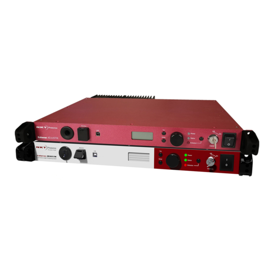
NKT Photonics Koheras ADJUSTIK HP Product Manual (116 pages)
Brand:
NKT Photonics
| Category:
Measuring Instruments
| Size: 14.98 MB
Table of Contents
Guide Overview
3
Safety
3
Terminology
3
Target Audience
3
Chapters Inside
4
Added Information and Safety Notices
4
Revision
5
Table of Contents
7
Tables
13
Figures
15
Procedures
17
Description
19
Laser Description
21
Terminology
21
Features and Options
21
Figure 1 ADJUSTIK Front View
21
High Power Variants
22
Theory of Operation
22
Safety
22
Module Variants
23
Center Wavelength
23
Output Power
23
Table 1 ADJUSTIK and ADJUSTIK HP Variant Specifications
23
Tuning Types
24
Front and Rear Panels
25
Front Panel
25
Rear Panel
26
Figure 2 ADJUSTIK Front Panel Layout
26
Optical Specifications
27
Laser Features
27
Thermal Tuning
27
Fast Wavelength Modulation
27
Figure 3 ADJUSTIK Rear Panel Layout
27
External Cavity Stabilization
28
Amplitude Modulation
28
Operating Mode
29
Trigger
29
High Temperature Shutdown
29
Power Verification
29
Table 2 Characteristics of Operating Modes
29
Optical Interface
30
Optical Fibers, Connectors and Adapters
30
Table 3 Example Optical Interface Specifications
30
Laser Control
31
User Interface
31
Chassis Labels
31
Figure 4 Top Panel Label Locations
31
Figure 5 Rear Panel Label Location
31
Table 4 Module Labels
32
Modulation
33
Fast Wavelength Modulation
33
Configuring Wavelength Modulation
33
Wavelength+/- Signal
34
Table 5 Wavelength Modulation Settings
34
Differential Input
35
Single-Ended to Differential
35
Singled-Ended Input
35
Figure 6 Differential Input Signal Graph for Wavelength Modulation
35
Figure 7 Single-Ended to Differential Circuit Example
35
Figure 8 Single-Ended Input Signal with 2.5 V Graph
36
Figure 9 Single-Ended Input W/2.5 V on an Unused Branch Example Circuit
36
Wavelength- to AGND
37
Figure 10 Single-Ended Input Signal with GND on an Unused Branch Graph
37
Figure 11 Single-Ended Input Connections with 0 V on an Unused Branch
37
Differential Output
38
Wavelength Modulation Coupling
38
Narrow Vs. Wide Modulation Range
38
Table 6 Narrow Vs Wide Band Wavelength Modulation
38
Figure 12 Differential Output Signal Graph
38
Frequency Response
39
Figure 13 X15 Variant Wavelength Modulation Response Graph
39
Amplitude Modulation
40
Amplitude+/- Signal
40
Figure 14 E15/Y10 Variant Wavelength Modulation Response Graph
40
Figure 15 Differential Input for Amplitude Modulation Graph
41
Figure 16 Single-Ended Input for Amplitude Modulation Graph
41
External Cavity Stabilization
42
Setting up External Cavity Stabilization
42
Figure 17 Koheras ADJUSTIK in a Pound-Drever-Hall Configuration
42
Operating the Laser
43
Front Panel Operation
45
Overview
45
Display
45
General
45
Figure 18 Front Panel Display and Controls
45
Wavelength
46
Power
46
Focus Position
46
Figure 19 OLED Display Layout
46
Tuning Increment
47
Errors
47
Figure 20 Wavelength Tuning Increment and Setpoint
47
Figure 21 Power Tuning
47
Status Badge
49
Figure 22 Example of an Error Message
49
Figure 23 Operational State Badge
49
Front Panel Controls
50
Key Switch
50
Tuning Dial and Button
50
Power Button
50
Emission Button
50
Enabling Emission from the Front Panel
51
Procedure 1 Enabling Emission
51
Tuning the Laser from the Front Panel
52
Procedure 2 Wavelength Tuning
52
Procedure 3 Power Level Tuning
52
Communicating with the Laser
53
CONTROL Software
53
Installing CONTROL Software
53
Connecting the Laser to a CONTROL PC
53
Procedure 4 Connecting a PC to the Laser Using a USB Cable
53
Ethernet Connection
54
Procedure 5 Connecting a PC to the Laser Using Ethernet
55
Enabling Emission
57
Safety
57
Preparation
57
Back Reflection
58
Enabling and Disabling Emission
58
Enable Emission (CONTROL)
58
Procedure 6 Turning on the Laser Using CONTROL
58
Using CONTROL
61
CONTROL Overview
61
Table 7 CONTROL Panels and Menu Items
61
Figure 24 GUI Panel Navigation
61
Relocating Panels
62
Figure 25 Panel Dragged to a New Location in the Main Window
62
Figure 26 Panels Dragged Outside the Main Window
62
Procedure 7 Relocating Panels
62
Toggling Panels Visible
63
Connecting to the Laser
63
Figure 27 Toggling Panel Visibility
63
Figure 28 Welcome Screen and Connecting
63
Device Selector
64
Figure 29 Connect Button
64
Figure 30 Device Selector Panel
64
Status Panel
65
Status Indicators
65
Figure 31 Status Panel
65
System Info
66
Measurements
66
WL Mod Button and Indicator
66
Amp Mod Button and Indicator
66
Emission Button
66
CONTROL Settings
68
Wavelength Modulation
68
Figure 32 GUI Settings
68
Figure 33 Wavelength Modulation - Internal Source
69
Figure 34 Wavelength Modulation - External Source
69
Figure 35 Internal Generator Waveform Selection - Type
70
Amplitude Modulation
71
Figure 36 Turning on Wavelength Modulation
71
Ethernet
72
Figure 37 Amplitude Modulation Source Settings
72
Figure 38 Internal Generator Amplitude Modulation Settings
72
Watchdog
73
Figure 39 Ethernet Setting
73
Clock
74
Front Panel
74
Figure 40 Watchdog Setting
74
Figure 41 Clock Setting
74
Figure 42 Front Panel Setting
75
View
76
Figure 43 View Setting
76
CONTROL Menu Items
77
Key Updater Tool
77
Figure 44 Menu Items
77
Procedure 8 Using the Key Updater Tool
77
Log Downloader
78
Procedure 9 Using the Log Downloader
78
Extensions Overview
79
Figure 45 Extensions Overview
80
CONTROL - Control Panel
81
Power Mode
81
Current Mode
81
Figure 46 Operating Mode Set to Power
81
Device Monitor
82
Table 8 Device Monitor Parameters
82
Application Log
83
Figure 47 Serial Monitor
83
Installing the Laser
85
Mechanical Installation
87
General
87
Heat Dissipation
87
Figure 48 Rear Panel Heat Sink
87
Rack Mounting the Laser
88
Placing the Laser on a Table or Shelf
88
Figure 49 ADJUSTIK - Rack Mounted
88
Figure 50 Rubber Mounting Feet
89
Figure 51 Table or Shelf Placement
89
Operating and Storage Environment
90
Connecting the Laser
91
Connecting the Safety Interlock
91
Simplified Interlock Operation
91
Interlock Alarm
92
Acknowledging Interlock Alarms
92
Figure 52 Interlock Connected to a Door Switch - Laser on
92
Figure 53 Interlock Connected to a Door Switch - Laser SHUTDOWN
92
Connecting an Interlock Switch
93
Bus Defeater
93
Figure 54 Bus Defeater
93
Procedure 10 Connecting the Door Interlock Circuit
93
Connecting Power
94
Connecting Modulation Signals
94
Connecting the Trigger Input or Output
94
Table 9 Power Specifications
94
Input Trigger
95
Output Trigger
95
Figure 55 Trigger Input Circuit
95
Figure 56 Trigger Output Circuit
95
Connecting the Optical Output
96
Cleaning of Fiber Facets
96
Cleaning Tools
96
Figure 57 Lint-Free Wipe Example
97
Figure 58 Example of a Fiber Cleaning Cartridge
97
A Specifications
101
Table 10 Koheras ADJUSTIK Optical Specifications
101
Table 11 Koheras ADJUSTIK HP Optical Specifications
102
Table 12 Mechanical Dimensions
102
Table 13 Operating and Storage Environment
103
Table 14 Electrical
103
Figure 59 Mechanical Dimensions
103
B Service and Support Information
105
Servicing the Laser
105
Opening the Laser Chassis
105
WARRANTY VOID if REMOVED Label
105
Figure 60 Warranty Seal
105
Support Contact Details
106
Support Website
106
Shipping Address
106
Disposal
106
Within EU Territory
106
Outside EU Territories
106
C Interface Pin Assignments
107
Modulation Input/Output
107
External Bus
107
Table 15 Modulation Connector Pin Assignment
107
Table 16 External Bus Pin Assignment
107
D Installing CONTROL Software
109
Installing CONTROL
109
Procedure 11 Installing CONTROL
109
Advertisement
NKT Photonics Koheras ADJUSTIK HP Product Manual (115 pages)
Low Noise Single Frequency Laser System
Brand:
NKT Photonics
| Category:
Measuring Instruments
| Size: 12.7 MB
Table of Contents
Guide Overview
3
Safety
3
Terminology
3
Table of Contents
5
Tables
11
Figures
13
Procedures
17
Koheras Adjustik (Hp) Description
19
Laser Description
21
Chassis and Front Panel Style
21
Terminology
21
Figure 1 ADJUSTIK Front Panel
21
Figure 2 ADJUSTIK HP Front Panel
21
Features and Options
22
High Power Variants
22
Theory of Operation
23
Safety
23
Module Variants
24
Part Numbers
24
Center Wavelength
24
Output Power
24
Table 1 ADJUSTIK and ADJUSTIK HP Variant Specifications
24
Tuning Types
25
Front and Rear Panels
26
Front Panel
26
Rear Panel
27
Figure 3 ADJUSTIK HP Front Panel Layout
27
Optical Specifications
28
Laser Features
28
Thermal Tuning
28
Fast Wavelength Modulation
28
Figure 4 ADJUSTIK Rear Panel Layout
28
External Cavity Stabilization
29
Amplitude Modulation
29
Operating Mode
29
Trigger
30
High Temperature Shutdown
30
Power Verification
30
Table 2 Characteristics of Power Modes
30
Optical Interface
31
Optical Fibers, Connectors and Adapters
31
Table 3 Example Optical Interface Specifications
31
Laser Control
32
User Interface
32
Status Leds
33
Table 4 Status Leds
33
Chassis Labels
34
Figure 5 Top Panel Label Locations
34
Figure 6 Rear Panel Label Location
34
Table 5 Module Labels
35
Modulation
37
Fast Wavelength Modulation
37
Configuring Wavelength Modulation
37
Wavelength+/- Signal
38
Table 6 Wavelength Modulation Settings
38
Differential Input
39
Single-Ended to Differential
39
Singled-Ended Input
39
Figure 7 Differential Input Signal for Wavelength Modulation
39
Figure 8 Single-Ended to Differential
39
Figure 9: Single-Ended Input Signal with 2.5 V
40
Figure 10 Single-Ended Input with 2.5 V on an Unused Branch
40
Wavelength- to AGND
41
Figure 11 Single-Ended Input Signal with GND on an Unused Branch
41
Figure 12 Single-Ended Input Connections with 0 V on an Unused Branch
41
Differential Output
42
Wavelength Modulation Coupling
42
Narrow Vs. Wide Modulation Range
42
Table 7 Narrow Vs Wide Band Wavelength Modulation
42
Figure 13 Differential Output Signal
42
Frequency Response
43
Figure 14 X15 Variant Wavelength Modulation Response
43
Amplitude Modulation
44
Amplitude+/- Signal
44
Figure 15 E15/C15/Y10 Variant Wavelength Modulation Response
44
Figure 16 Differential Input for Amplitude Modulation
45
Figure 17 Single-Ended Input for Amplitude Modulation
45
External Cavity Stabilization
46
Setting up External Cavity Stabilization
46
Figure 18 the Laser Used in a Pound-Drever-Hall Configuration
46
Operating the Laser
47
Front Panel Menu
49
Overview
49
General Operation
49
Table 8 Front Panel Menu Items
49
Menu Items
50
Top Menu
50
Figure 19 Top Level Menu
50
Wavelength
51
Wavelength Display
51
W1 Modulation
51
Figure 20 Wavelength Setting Menu
51
Figure 21 Wavelength Display Menu - Set as Absolute
51
Figure 22 Wavelength Modulation - on
51
W1 Mod. Gain
52
W1 Mod. Source
52
W1 Mod. Coupling
52
Figure 23 Wavelength Modulation Gain Setting Menu
52
Figure 24 Wavelength Modulation Source Signal Set to Internal
52
Figure 25 Wavelength Modulation Signal Coupling Set to AC
52
W1 Mod. Range
53
Power /Current Mode
53
Power
53
Figure 26 Wavelength Modulation Range Set to Narrow
53
Figure 27 Operation Mode Set to Constant Power Mode
53
Figure 28 Power Tuning Menu
53
Power Unit
54
Watchdog Timer
54
Display Backlight
54
Figure 29 Power Unit Menu - Set to Mw
54
Figure 30 Watchdog Timer Setting
54
Figure 31 Setting the Intensity Level of the LCD Panel Back Light
54
IP Address
55
Emission Button
55
Figure 32 IP Address Setting
55
Communicating with the Laser
57
CONTROL Software
57
Installing CONTROL Software
57
Connecting the Laser to a CONTROL PC
57
Procedure 1 Connecting a PC to the Laser Using a USB Cable
57
Ethernet Connection
58
Procedure 2 Connecting a PC to the Laser Using Ethernet
59
Turning on the Laser
61
Safety
61
Preparation
61
Back Reflection
62
Enabling and Disabling Emission
62
Enable Emission (CONTROL)
62
Procedure 3 Turning on the Laser Using CONTROL
63
Enable Emission (Front Panel)
64
Procedure 4 Turning on the Laser Using the Front Panel Controls
65
Using CONTROL
69
CONTROL Overview
69
Table 9 CONTROL Panels and Menu Items
69
Figure 33 GUI Panel Navigation
69
Relocating Panels
70
Figure 34 Panel Dragged to a New Location in the Main Window
70
Figure 35 Panels Dragged Outside the Main Window
70
Procedure 5 Relocating Panels
70
Toggling Panels
71
Connecting to the Laser
71
Device Selector
71
Figure 36 Panels Dragged Outside the Main Window
71
Figure 37 Welcome Screen and Connecting
71
Figure 38 Device Selector Panel
71
Status Panel
72
Status Indicators
72
Figure 39 Status Panel
72
System Info
73
Measurements
73
WL Mod Button and Indicator
73
Amp Mod Button and Indicator
73
Emission Button
73
CONTROL Settings
74
Wavelength Modulation
74
Figure 40 GUI Settings
74
Figure 41 Wavelength Modulation - Internal Source
75
Figure 42 Wavelength Modulation - External Source
75
Figure 43 Internal Generator Waveform Selection (Type)
75
Amplitude Modulation
77
Figure 44 Turning on Wavelength Modulation
77
Figure 45 Power and Current Mode Controls
77
Ethernet
78
Figure 46 Internal Amplitude Modulation Settings
78
Watchdog
79
Figure 47 Ethernet Setting
79
Clock
80
Figure 48 Watchdog Setting
80
Figure 49 Clock Setting
80
View
81
CONTROL Menu Items
81
Figure 50 View Setting
81
Figure 51 Menu Items
81
Serial Monitor
82
Application Log
82
Figure 52 Serial Monitor
82
Figure 53 Serial Monitor
82
CONTROL - Control Panel
83
Power Mode
83
Current Mode
83
Figure 54 Operating Mode Set to Power
83
Installing the Laser
85
Mechanical Installation
87
General
87
Heat Dissipation
87
Figure 55 Rear Panel Heat Sink
87
Rack Mounting the Laser
88
Placing the Laser on a Table or Shelf
88
Figure 56 Image of the Laser Rack Mounted
88
Operating and Storage Environment
89
Figure 57 Rubber Mounting Feet
89
Figure 58 Table or Shelf Mounting
89
Connecting the Laser
91
Connecting the Safety Interlock
91
Simplified Interlock Operation
91
Figure 59 Interlock Connected to a Door Switch - Laser on
91
Interlock Alarm
92
Acknowledging Interlock Alarms
92
Connecting an Interlock Switch
92
Figure 60 Interlock Connected to a Door Switch - Laser SHUTDOWN
92
Bus Defeater
93
Connecting Power
93
Table 10 Power Specifications
93
Procedure 6 Connecting the Door Interlock Circuit
93
Connecting Modulation Signals
94
Connecting the Trigger Input or Output
94
Input Trigger
94
Output Trigger
94
Figure 61 Trigger Input Circuit
94
Connecting the Optical Output
95
Figure 62 Trigger Output Circuit
95
Cleaning of Fiber Facets
96
Cleaning Tools
96
Appendices
97
A Specifications
99
Table 11 Koheras ADJUSTIK Optical Specifications
99
Table 12 Koheras ADJUSTIK HP Optical Specifications
100
Table 13 Mechanical Dimensions
100
Table 14 Operating and Storage Environment
100
Table 15 Electrical
100
Table 16 Safety and Regulatory Compliances
101
Table 17 Mechanical Dimensions
101
B Service and Support Information
103
Servicing the Laser
103
Opening the Laser Chassis
103
WARRANTY VOID if REMOVED Label
103
Support Contact Details
104
Support Website
104
Shipping Address
104
C Interface Pin Assignments
105
Modulation Input/Output
105
External Bus
105
Table 18 Modulation Connector Pin Assignment
105
Table 19 External Bus Pin Assignment
105
D CONTROL Software
107
Installing CONTROL
107
Procedure 7 Installing CONTROL
107
Table 20 ADJUSTIK and ADJUSTIK HP Part Numbers
113
Advertisement
Related Products
NKT Photonics Koheras ACOUSTIK
NKT Photonics Koheras HARMONIK Series
NKT Photonics Koheras HARMONIK
NKT Photonics Koheras ADJUSTIK
NKT Photonics Koheras BOOSTIK
NKT Photonics Koheras BASIK
NKT Photonics Koheras BOOSTIK LC
NKT Photonics Koheras BOOSTIK HP
NKT Photonics ADJUSTIK
NKT Photonics ADJUSTIK HP
NKT Photonics Categories
Measuring Instruments
Water Filtration Systems
Amplifier
Control Unit
Industrial Electrical
More NKT Photonics Manuals
Login
Sign In
OR
Sign in with Facebook
Sign in with Google
Upload manual
Upload from disk
Upload from URL