Table of Contents
Advertisement
Quick Links
Advertisement
Table of Contents

Related Manuals for NKT Photonics Koheras ACOUSTIK


Summary of Contents for NKT Photonics Koheras ACOUSTIK
- Page 1 Koheras ACOUSTIK Multi-Channel Modular Laser System PRODUCT GUIDE Item 800-633-01...
- Page 2 PRODUCT GUIDE This guide includes the following NKT Photonics Lasers: Koheras ACOUSTIK 16 slot multi-channel rack-mountable modular laser system Koheras ACOUSTIK Product Guide Revision 1.0 09-2021 W-10456...
-
Page 3: Guide Overview
“system labeling update” on page Terminology This guide refers to the Koheras ACOUSTIK as the “laser system” or simply “system”. The Koheras ACOUSTIK is built specifically to contain laser modules within its slots as components of a multi-laser system. In specific cases where a distinction is required, this guide will use the actual module names. - Page 4 Chapters inside This guide includes the following chapters: • Chapter I “Description” — Describes the system including its general operational principles, management and interfaces. • Chapter 2 “Mechanical Installation” — Includes information on how to correctly install the system. Information within this chapter include a focus on providing adequate temperature regulation.
-
Page 5: Table Of Contents
Guide Overview ....................3 BOOSTIK amplifiers ................3 Terminology ..................3 TABLES ....................9 FIGURES ................... 11 PROCEDURES .................. 13 KOHERAS ACOUSTIK DESCRIPTION Section 1 1 Description ....................17 Optical output ..................17 Slot configurations ................18 Front and rear panels ................18 Front panel .................. - Page 6 Heat dissipation ..................29 BOOSTIK modules ................29 Rack mounting the system ..............31 Front and rear rack mounting ............31 Rack-mounted cooling ............... 32 Blank covers ..................32 Placing the system on a surface ............. 33 Operating and storage environment ............33 3 Connecting the ACOUSTIK ................
- Page 7 Preparation ..................... 47 Enabling emission from all modules ............48 Enabling emission from an individual BASIK module ......50 Enabling emission from an individual BOOSTIK module ....... 53 6 Using CONTROL ..................57 CONTROL overview ................57 Relocating panels ................58 Toggling panels ..................
- Page 8 Appendices A Specifications ....................81 B Service and Support Information ..............83 Servicing the laser .................. 83 Support contact details ................84 Support website ................. 84 Shipping address ................84 C Interface Pin Assignments ................85 Modulation input/output ................85 External bus ...................
-
Page 9: Tables
TABLES Table 1: Status LEDs..................23 Table 2: System labels ..................25 Table 3: BOOSTIK installation recommendations ..........30 Table 4: Power specifications................38 Table 5: CONTROL panels and menu items............ 57 Table 6: Module overview fields ............... 76 Table 7: Mechanical dimensions ..............81 Table 8: Operating and storage environment .......... -
Page 11: Figures
FIGURES Figure 1: ACOUSTIK front panel ..............17 Figure 2: Multiplexed optical output port ............18 Figure 3: ACOUSTIK front panel layout - BASIK modules only ...... 19 Figure 4: System with a single BASIK and BOOSTIK module installed ..19 Figure 6: Top panel label locations .............. - Page 12 Figure 30:: Wavelength modulation - ACOUSTIK source selected ....66 Figure 31: Internal generator waveform selection (Modulation Type) ..... 67 Figure 32: Turning on wavelength modulation ..........69 Figure 33: Amplitude modulation settings ............69 Figure 34: Ethernet setting ................70 Figure 35: Watchdog setting ................
-
Page 13: Procedures
PROCEDURES Procedure 1: Connecting the door interlock circuit.......... 37 Procedure 2: Connecting a PC to the ACOUSTIK using a USB cable.... 43 Procedure 3: Connecting a PC to the ACOUSTIK using Ethernet ....45 Procedure 4: Enabling emission from all inserted modules......48 Procedure 5: Enabling emission from an individual BASIK module .... -
Page 15: Koheras Acoustik Description
SECTION 1 KOHERAS ACOUSTIK DESCRIPTION This section provides a description of the laser and its system types. It includes the following topics: • “Description” on page 17 • “Front and rear panels” on page 18 • “Modulation” on page 22 •... -
Page 17: Description
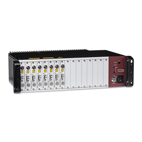
Description The Koheras ACOUSTIK is a rack or table mounted 16 slot modular laser system designed to integrate multiple Koheras BASIK fiber laser modules and optional BOOSTIK amplifier modules (2 maximum). Modules slide into the system’s slots and mate with a backplane electrical connector. Inserted BASIK modules require one slot each and BOOSTIK modules occupy two slots. -
Page 18: Slot Configurations
Class 4 rating at its optical output. Multiplexed optical output The Koheras ACOUSTIK system is specified with or without optical multiplexing. Without multiplexing, the individual optical outputs of each module is employed. When the multiplexed optical output feature is included, the optical output of inserted modules is combined into a signal optical output on the rear panel of the laser. -
Page 19: Figure 3: Acoustik Front Panel Layout - Basik Modules Only
Front and rear panels needed, however only the backplane connector in the right side slot connects to the module’s rear panel electrical connector. The front panel also incorporates controls and indicators for managing the inserted modules. These include: status LED indicators, an emission button, a security and interlock key switch, and an AC mains switch. -
Page 20: Rear Panel
USB type B port This is the system management port, use a USB cable to connect this port to a PC. You can control the inserted modules using the NKT Photonics CONTROL application. Emission control button Pressing the button enables or disables emission from all modules inserted and ready in the system. - Page 21 Front and rear panels Figure 5 ACOUSTIK rear panel layout Multiplexed optical output – OPTIONAL AC mains input LEMO door interlock connector 10/100 BASE-T Ethernet port External bus female D-sub 15 pin connector 7 Cooling fins Modulation & Trigger I/O male D-sub 9 pin connector Note: Pin assignments of connectors are described in Appendix C...
-
Page 22: Modulation
ACOUSTIK is placed on the connector to loop back the interlock safety circuit. Modulation The Koheras ACOUSTIK system provides a single point connector for connection of external wavelength and amplitude modulation signals that are fed to the inserted BASIK modules through the system backplane. Any signals on the pins are only used by modules that support the modulation features. -
Page 23: Status Leds
Status LEDs Section 2 includes chapters on using CONTROL and how to manage and operate the system and any inserted modules. Status LEDs The front panel houses three status LEDs as described in Table 1. The LEDs are located on the front panel as shown in Figure Table 1 Status LEDs LED Name... -
Page 24: System Labels
Koheras ACOUSTIK Safety, Handling and Regulatory Information. System labels A Koheras ACOUSTIK system has a number of labels placed on it that indicate hazards, regulatory, or manufacturing information. The labels are located on the panels described in... -
Page 25: Table 2 System Labels
System labels Table 2 System labels Label Panel Description Classification - Emission Safety information stating the laser emission Hazards hazards and the laser’s class rating. INVISIBLE LASER RADIATION AVOID EXPOSURE TO BEAM CLASS 3B LASER PRODUCT Classification - Emission Safety information stating the laser emission Hazards hazards and the laser’s class rating. - Page 26 System labels...
-
Page 27: Installing An Acoustik System
SECTION 2 INSTALLING AN ACOUSTIK SYSTEM This section describes how to install the laser and includes the chapters: • “Mechanical Installation” on page 29 • “Connecting the ACOUSTIK” on page 35... -
Page 29: Mechanical Installation
Mechanical Installation Install the system either on a flat surface or rack-mounted in a standard 19 inch rack. This section provides information on inserting modules and mounting or placing the system to for optimal function and ensure that heat generated by the laser is adequately dissipated. -
Page 30: Table 3 Boostik Installation Recommendations
Heat dissipation Table 3 BOOSTIK installation recommendations Item Recommendation Value # of BOOSTIK modules Maximum 2 BOOSTIK modules ≤ 2 per ACOUSTIK system. Installation slots Table 13 on page Slots Do not install two BOOSTIK 6-10 modules in adjacent slots. 11-14 Slots 15-16 not recommended. -
Page 31: Rack Mounting The System
Further, when a Koheras ACOUSTIK system is installed in a rack, ensure to fasten the system using all four mounting holes in the system flanges, two holes on each side. -
Page 32: Rack-Mounted Cooling
Rack mounting the system Rack-mounted Once mounted in a rack, it is important that there is adequate airflow at the rear of the laser so that the cooling fins can effectively dissipate the heat generated cooling by the laser – see“Heat dissipation”... -
Page 33: Placing The System On A Surface
Warning: Although The Koheras ACOUSTIK itself is a 16-slot system, it houses both class 3B and class 4 laser products, therefore its operation facility and con- dition must comply with the standards listed below or similar: •... - Page 34 Operating and storage environment...
-
Page 35: Connecting The Acoustik
Connecting the ACOUSTIK This chapter provides information on connecting the system and its modules. For information on how to connect: • The safety interlock – see “Connecting the safety interlock” on page 35 • Power – see “Connecting power” on page 38 •... -
Page 36: Figure 13 Interlock Connected To A Door Switch - Laser Shutdown
Shutdown Laser Caution: Do not short-circuit the LEMO interlock connector. Short-circuiting the in- terlock circumvents safety regulations and NKT Photonics does not take liability for any injuries or damage caused by doing so. Caution: The switch connected to the interlock must be of an approved type. Fur- ther, the switch must be installed in a manner so that its operation cannot be fixed in the open state using a tool. -
Page 37: Connecting An Interlock Door Switch
LEMO Plug (door switch circuit) The laser is shipped with a pre-wired LEMO interlock plug. If you need a new LEMO plug assembly contact NKT Photonics, see “Support contact details” on page 84. The plug should be used to connect the door interlock circuit as... -
Page 38: Connecting Power
Connecting power Note: When no accessories are connected to the ACOUSTIK system as is the typical case, place the bus defeater on the rear panel External bus connector of the ACOUSTIK. Figure 15 External bus defeater Connecting power Power is supplied to an ACOUSTIK system through its rear AC input connector. The connector is a standard C14 inlet designed for use with a C13 AC power cord. -
Page 39: Input Trigger
Connecting the trigger input or output Input trigger When the trigger pin is set as an input, a positive active high signal applied to the trigger pin enables emission. The diagram Figure 16 shows a schematic of the trigger input. Figure 16 Trigger input circuit Output trigger When the trigger feature is sets the pin as an output, the trigger pin should be... -
Page 40: Connecting Basik Optical Output To A Boostik Input
Either clean the connector using a suitable process or contact NKT Photonics support if replacement is necessary. Figure 18 ACOUSTIK – single BASIK and BOOSTIK modules... -
Page 41: Operating The Acoustik System
SECTION 3 OPERATING THE ACOUSTIK SYSTEM This section describes how to install the laser and includes the chapters: • “Mechanical Installation” on page 29 • “Connecting the ACOUSTIK” on page 35 This section describes how to manage and operate the laser and includes the chapters: •... -
Page 43: Communicating With The Acoustik
PC and the laser using either a USB or Ethernet connection. CONTROL software ACOUSTIK systems are shipped with NKT Photonics CONTROL software installer on a USB key. You can also download the most recent CONTROL application installer from the following link: https://www.nktphotonics.com/lasers-fibers/support/software-drivers/... - Page 44 If necessary, wait for the Windows device manager to install the USB drivers on your PC needed for the USB connection to the ACOUSTIK. Launch CONTROL software by either: • clicking on Windows – Start – Programs – NKT Photonics –CONTROL – or – • double clicking the CONTROL shortcut on the desktop The CONTROL window opens.
-
Page 45: Ethernet Connection
Connecting the ACOUSTIK to a PC with CONTROL Ethernet To connect an ACOUSTIK system to a PC using Ethernet, the PC and the system must have their Ethernet ports connected to the same or separate IPv4 subnets. If separate connection subnets are used, ensure they are reachable from each other. - Page 46 Connecting the ACOUSTIK to a PC with CONTROL Action Click the Save button to save the configuration of the new Ethernet network connection. To delete or modify a configured network Delete button port: Highlight the port and click the delete button. - or - Edit button Click the edit button.
-
Page 47: Enabling Emission
Enabling emission from the modules inserted in an ACOUSTIK will emit hazardous laser Class 3B and with BOOSTIK modules, Class 4 radiation. Ensure to observe and implement all safety regulations, warnings and cautions in this guide and the Koheras ACOUSTIK Safety, Handling and Regulatory Information document before continuing. -
Page 48: Enabling Emission From All Modules
Enabling emission from all modules Warning: Ensure all fiber connector facets (tips) are clean. Optical power transmit- ted through a connector may burn particles on the connector face damaging it. Note: When connecting an output fiber patch cord, ensure to match it with an ap- propriate fiber type. - Page 49 Enabling emission from all modules Action 3 Ensure the front panel key switch is set to the ON position. 4 Observe the Interlock indicator in the status panel, if it is RED and the Status indicator is AMBER, check for the following conditions: a The door interlock circuit is open –...
-
Page 50: Enabling Emission From An Individual Basik Module
Enabling emission from an individual BASIK module Action 7 Observe status and parameters of individual modules in the Module overview panel. Status indicators for individual modules 8 a Set the reference wavelength offset for all inserted ACOUSTIK modules using the slider in the Wavelength offset setting control. -
Page 51: Procedure 5 Enabling Emission From An Individual Basik Module
Enabling emission from an individual BASIK module Procedure 5 Enabling emission from an individual BASIK module Action 1 Connect to the ACOUSTIK system using the procedures in Communicating with the ACOUSTIK. 2 Select the module to enable; click on its icon in the Device Selector or the Module Overview panel (see Module... - Page 52 Enabling emission from an individual BASIK module Action 5 When the module is selected and the Interlock indicator is GREEN, click the Emission button once to enable emission. The emission indicator (next to the Emission button) turns ON RED. NOTE: Only the selected module’s emission status changes.
-
Page 53: Enabling Emission From An Individual Boostik Module
Enabling emission from an individual BOOSTIK module Action 7 a Set the reference wavelength offset for λ λ the module using the slider in the offset slider offset input field Wavelength offset setting control. To adjust the wavelength, click-hold the slider to change its position. -
Page 54: Procedure 6 Enabling Emission From An Individual Boostik Module
Enabling emission from an individual BOOSTIK module Procedure 6 Enabling emission from an individual BOOSTIK module Action 1 Enable emission from the BASIK seed laser module connected to the optical input of the BOOSTIK - see Procedure 2 The status panel of the ACOUSTIK light source connected to the ACOUSTIK should show the following indicators: •... - Page 55 Enabling emission from an individual BOOSTIK module Action 4 Before turning ON the BOOSTIK, check that the input from the BASIK module is ON. a In the Module overview panel, locate the Power input field for the BOOSTIK and check that the module measures a power level between 10 to 200 mW.
- Page 56 Enabling emission from an individual BOOSTIK module Action 7 To disable emission from the amplifier, click Status indicator ON the Emission button once. AMBER The Status indicator changes to ON AMBER and the Emission button indicator turns OFF Click the Emission button OFF...
-
Page 57: Using Control
Using CONTROL CONTROL overview The CONTROL interface includes multiple panels and a selection of menu drop down items in the upper left corner. You can add or remove the displayed panels and panels can be dragged within the main window or into separate windows. Figure 19 shows the CONTROL panels which are briefly described Table 5... -
Page 58: Relocating Panels
CONTROL overview Relocating panels The panels displayed by CONTROL can be dragged to other positions within the main interface or into a separate floating panel. Procedure 7 describes how to move a panel: Procedure 7 Relocating panels Action Left click hold the top title bar of a panel. While holding the left mouse button down, drag the panel to another position in the main window. -
Page 59: Toggling Panels
Navigation Toggling panels Use the Menu > Window drop down menu to check and uncheck panels to be displayed. A blue highlighted check mark indicates the panel is displayed. Figure 22 Panels dragged outside the main window Check the panels to display them Note: Clicking the X in the upper right corner of any panel will also close it. -
Page 60: Acoustik Modules - Control Interface
Navigation Figure 24 Selecting the controller or a module to display in CONTROL Click the icon system controller to select it Modules Click Note: When the controller of the system is selected, information about the sys- tem is displayed along with summary information of all modules. When a module is selected, the CONTROL interface only displays the selected module controls and status information. -
Page 61: Status Panel - Acoustik System
Status panel - ACOUSTIK system Status panel - ACOUSTIK system The status panel for the system provides status indicators, error messages, emission control function and a settings drop down menu. Figure 25 Status panel Click Status indicators The panel displays the following indicators: Interlock Indicates if the door interlock and external bus interlock circuit of the system is closed or open. -
Page 62: System Info
Status panel - ACOUSTIK system • Flashing Green – Emission from one or more of the inserted modules has not stabilized (warming-up). • Flashing Amber – The system is scanning for inserted modules or connected accessories. • ON Amber – Interlock error or interlock reset required •... -
Page 63: Control Settings
CONTROL settings The Emission button indicator turns ON RED when at least one or more modules have emission enabled. Otherwise, it is OFF GREY. Note: BOOSTIK LC modules receiving input from a seed module that fails to en- able emission, will also be unable to turn on. Warning: Class 3B laser emission is emitted from inserted ACOUSTIKmodules when the Emission button LED is ON RED. -
Page 64: Wavelength Modulation
CONTROL settings Setting Item Function Watchdog Enables and sets the watchdog timeout. Watchdog on page 71 Clock Sets the system clock time. Clock on page 71 View Provides a check box to enable displaying the system View on page 72 information on the status panel. -
Page 65: Figure 28 Wavelength Modulation - Source Selection
CONTROL settings Figure 28 Wavelength modulation - source selection Source (modulation) When using CONTROL to set the wavelength modulation source, perform the following. Select and highlight the desired module in the Device Selector panel. 2. From the Settings drop down menu, select Wavelength modulation. 3. -
Page 66: Figure 29: Wavelength Modulation - Module Source Selection
CONTROL settings Figure 29: Wavelength modulation - module source selection 4. If the BASIK module is set to Internal, go to step 8. 5. For BASIK modules set to External or Both, select and highlight the ACOUSTIK system in the device selector panel. 6. -
Page 67: Figure 31 Internal Generator Waveform Selection (Modulation Type)
CONTROL settings Note: The Settings - Wavelength modulation menu item is only available for an ACOUSTIK system when at least one inserted BASIK module includes the wave- length modulation feature. Caution: You can set a BASIK module in the system as the signal source. DO NOT set more then one module as the source. - Page 68 CONTROL settings Frequency (internal generator - internal only) When the wavelength modulation source of the ACOUSTIK controller is set to Internal, the frequency of the internal generator signal can be adjusted. The range of frequency adjustment depends on the signal type: •...
-
Page 69: Amplitude Modulation
CONTROL settings Figure 32 Turning on wavelength modulation Click to enable wavelength modulation Amplitude Similar to Wavelength modulation, inserted BASIK modules can have their optical output power modulated by either an internal generator of the system or an modulation external source. Figure 33 Amplitude modulation settings Note: The Amplitude Modulation settings menu item is only available if there is at... -
Page 70: Ethernet
CONTROL settings Type (amplitude modulation) Selects the amplitude modulating waveform generated by the system controller. Select either Sinusoidal, Triangle, Sawtooth or Inverse sawtooth. Frequency (amplitude modulation) The frequency of the internal generator amplitude modulation signal can be adjusted. The range of frequency adjustment depends on the signal type: •... -
Page 71: Watchdog
A unique MAC address of the ACOUSTIK is displayed only and cannot be set. Watchdog The Koheras ACOUSTIK features a watchdog for monitoring of USB or Ethernet communication. If CONTROL is disconnected from the system, the watchdog disables emission on each module after a set timeout expires. -
Page 72: View
CONTROL menu items Date Displays the system date in the format DD/MM/YYYY. Time Displays the system time in 24 hour format: HH:MM:SS. Set to computer clock Click the Set button to updated the system time and date from a connected PC’s current time and date setting. -
Page 73: Serial Monitor
CONTROL menu items Figure 38 Menu items Menu Item Function File Exits the GUI program Connect / Disconnects the currently connected device from Disconnect GUI. Window Selects whether or not to display the Application Log and the serial monitor. Help Displays the current version of GUI and provides access to the included GUI user help. -
Page 74: Figure 40 Serial Monitor
CONTROL menu items Figure 40 Serial Monitor Clear the log Save the log to file Print the log The panel is enabled by placing a check mark on the Window pull down menu next to the Application Log item. To close the panel click on the upper right corner “X”. -
Page 75: Control Panel
Module overview When CONTROL connects to a Koheras ACOUSTIK system, a Module overview panel is displayed beneath the Control and Status Panels. As shown in Figure each row in the overview represents an inserted module and the column fields display the module parameters and statuses. -
Page 76: Table 6 Module Overview Fields
Module overview Figure 42: Module overview - all fields selected The following information is available from each of the available fields: Table 6 Module overview fields Column heading Description Module system slot number Reference WL Base wavelength of the module in nm Actual WL Output wavelength of the module in nm WL offset Setpoint... -
Page 77: Toggling And Sorting The Overview Fields
Module overview Toggling and In the module overview, you can sort the order of the fields and select the fields to display. sorting the overview fields Setting the field order With your mouse, click-hold on a field in the header and drag it to a new location to change the order of the fields in the header. - Page 78 Module overview...
-
Page 79: Appendices
APPENDICES The appendices include: Appendix A on page 81 Specifications • Appendix B on page 83 Service and Support • Appendix C on page 85 Interface Pin Assignments • Appendix D on page 87 CONTROL Installation • Appendix E on page 93 ACOUSTIK Slot Configuration Rules •... -
Page 81: A Specifications
Specifications Table 7 Mechanical dimensions All system models 130 x 463 x 348 mm Size (H x W x D) (5.12 x 18.23 x 13.70 in) Weight ~ 10 kg (~22 lb) Table 8 Operating and storage environment All system Models 15°C to 60°C (59°F to 140°F) Operating Temperature -20°C to 60°C (-4°F to 140°F) -
Page 82: Figure 44 Mechanical Dimensions
Figure 44 Mechanical dimensions 125.00 4.50 302.50 45.00 483.00... -
Page 83: B Service And Support Information
Service and Support Information Servicing the laser The Koheras ACOUSTIK has no user serviceable components. In case of malfunction, contact NKT Photonics using the support channels in section “Support contact details”. Caution: Do not open the system. The Koheras ACOUSTIK is equipped with Figure 45) on its system panels. -
Page 84: Support Contact Details
Support contact details Support contact details If you need help or have questions regarding your Koheras ACOUSTIK or any of its modules, contact NKT Photonics through our website below. Support website 1. Go to: https://www.nktphotonics.com/lasers-fibers/support/technical-support-and- customer-service/ 2. Scroll down and click or press: 3. -
Page 85: C Interface Pin Assignments
Emission Collector output with an internal 270 Ω resistor in series.Outputs a logic high when the Koheras ACOUSTIK system has laser emission ON. To indicate emission with an LED, its anode can be connected directly to this pin and its cathode connected to the GND (pins 5,6, 13 or 14). - Page 86 External bus Pin # Signal Description Interlock Logic Outputs a logic high (5V) when the interlock circuit is closed and has Output been reset. This signal can be used to control safety related precautions on the External Bus. 5,6,13,14 0 volt ground. 7,8,15 +12 V 12 volt supply voltage for external accessories.
-
Page 87: D Control Installation
CONTROL Installation Installing CONTROL Download the installer from: https://www.nktphotonics.com/lasers-fibers/support/software-drivers/ Procedure Follow the steps in Procedure 8 Installing CONTROL Action On the PC, launch the installer package and then click the Installer Run button. The installation wizard appears. Click Next to continue. - Page 88 Installing CONTROL Action Accept to use the default installation directory or select another directory by clicking the Browse button. Click Next to continue. Uncheck the components you do not require. By default, all components will be installed. Click Next to continue. Read the End-User License Agreement, and select: “I accept the license.”.
- Page 89 Installing CONTROL Action The wizard will create a start menu folder with program short-cuts. Use the default name or enter a new name for the folder. Click Next to continue. Check the box to create a desktop shortcut to access Control.
- Page 90 Installing CONTROL Action Click Install to install NKTP Control software on your PC. Click Cancel if you want to abort the installation. The wizard displays a progress meter for the installation. NOTE: A normal install should only take a few seconds. Click Next to install the UART drivers for the PC USB port.
- Page 91 Installing CONTROL Action The drivers will be installed. The Silicon Labs drivers is installed successfully. Click Finish to end the installation wizard. CONTROL is now installed. Check the Run box to launch CONTROL when the Finish button is clicked. Click Finish.
- Page 92 Installing CONTROL...
-
Page 93: E Acoustik Slot Configuration Rules
ACOUSTIK Slot Configuration Rules Table 13 shows supported configurations of modules inserted in the ACOUSTIK slots according to the following: • BOOSTIK modules are only supported in the slot configurations shown. • 1 to 16 BASIK modules are supported. Adding a BOOSTIK module reduces the maximum number of BASIK modules by 2. - Page 94 # of ACOUSTIK system Slot # Config BOOSTIK Inserted...
- Page 96 Koheras ACOUSTIK Product Guide Revision 1.0 09-2021 W-10456...
Need help?
Do you have a question about the Koheras ACOUSTIK and is the answer not in the manual?
Questions and answers