Table of Contents
Advertisement
Advertisement
Table of Contents

Related Manuals for SPM Machine Guard MG4-REF11A


Summary of Contents for SPM Machine Guard MG4-REF11A
- Page 1 Instruction Manual Machine Guard MG4-REF11 A SPM Instrument AB • Box 504 • SE-645 25 Strängnäs • Sweden Technical data are subject to change without notice. Tel +46 152 225 00 • Fax +46 152 15075 • info@spminstrument.se • www.spminstrument.com...
-
Page 3: Table Of Contents
Technical specifications ............28 Trouble Shooting ..............30 SPM Instrument AB • Box 504 • SE-645 25 Strängnäs • Sweden Technical data are subject to change without notice. Tel +46 152 225 00 • Fax +46 152 15075 • info@spminstrument.se • www.spminstrument.com... -
Page 4: Safety Precautions
Before should be used. SPM Instrument AB • Box 504 • SE-645 25 Strängnäs • Sweden Technical data are subject to change without notice. Tel +46 152 225 00 • Fax +46 152 15075 • info@spminstrument.se • www.spminstrument.com... -
Page 5: Machine Guard Mg4-Ref11A
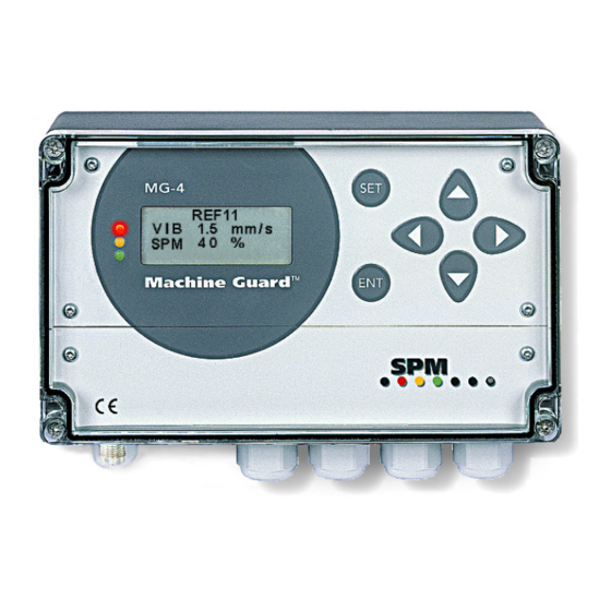
Machine Guard MG4-REF11A Machine Guard MG4-REF11A is a continuous monitoring unit. It measures vibration severity (VIB) and the mechanical shocks (SPM) arising when the disc segments in a refiner touches each other. It provides, for each channel: • Status display (green - red light) and system fault (yellow light) •... -
Page 6: General
Machine Guard MG4-REF11 A General A contact of the disc segments can be prevented using the SPM Shock Pulse Method. A shock pulse transducer measures the mechanical shocks arising when the disc segments touches each other. A shock pulse transducer (A) is fixed to the refiner housing so that mecha nical shocks from the segments are transmitted to the transducer with a minimum of reduction. -
Page 7: Mechanical Installation
The temperature range of the MG4-REF11A is 0 to 50 °C (32 to 122 °F). The maximum length of the transducer cables is 100 m for SPM shock pulse transducers type 42000. SPM Instrument AB • Box 504 • SE-645 25 Strängnäs • Sweden Technical data are subject to change without notice. -
Page 8: Electrical Installation Of Mg4
Read the Safety Precautions on page 2 before performing electrical installation. If you are in doubt, please contact your local SPM representative before installing the equipment. SPM Instrument AB • Box 504 • SE-645 25 Strängnäs • Sweden Technical data are subject to change without notice. - Page 9 OK (open or short circuit for VIB, TLT value below 15 for SPM). This will cause the connected analog output to go to approx. 0 mA. Setting TLT to OFF prevents the analog output from dropping below 4 mA.
-
Page 10: Connection To Plc Via Analog Output
DO = Digital Output 0 or 24 V to an external relay DCS = Distributed Control System SPM Instrument AB • Box 504 • SE-645 25 Strängnäs • Sweden Technical data are subject to change without notice. Tel +46 152 225 00 • Fax +46 152 15075 • info@spminstrument.se • www.spminstrument.com... -
Page 11: Programmed Measuring Parameters
Programmed measuring parameters The measuring and alarm parameters of an MG4-REF11A are programmed, using the keys on the front panel. The program is password protected, which means that a the password ‘SPM’ has to be input before any parameter can be changed. -
Page 12: Reset Default Parameters
Alarm delay: ....– – – SPM Instrument AB • Box 504 • SE-645 25 Strängnäs • Sweden Technical data are subject to change without notice. Tel +46 152 225 00 • Fax +46 152 15075 • info@spminstrument.se • www.spminstrument.com... -
Page 13: The Version Menu, Version And Setup
On line 4 you see the version numbers of the three processors CPU, VIB, and SPM. None of these settings can be changed. Press ENT to exit to the VERSION menu. -
Page 14: The Version Menu, Password And Stand-By
Measuring = OFF means that the analog and relay outputs are frozen (stand-by mode). This set- ting is selected before disconnecting any of the VIB or SPM input channels, else disconnecting a transducer will cause a system fault alarm. -
Page 15: Programming A Vibration Channel
). Enter the value from the transducer’s calibration / data card. SPM Instrument AB • Box 504 • SE-645 25 Strängnäs • Sweden Technical data are subject to change without notice. Tel +46 152 225 00 • Fax +46 152 15075 • info@spminstrument.se • www.spminstrument.com... - Page 16 Alarm delay is set in steps of 2 seconds by stepping to a number above 0 on menu (F). The maxi- mum is 600 seconds or 10 minutes. SPM Instrument AB • Box 504 • SE-645 25 Strängnäs • Sweden Technical data are subject to change without notice.
-
Page 17: Programming A Spm Channel
Select the SPM channel with the SET key and press ENT to get the sequence of programming menus. ”TLT” on line 2 of menu (A) shows the transducer line status. For an SPM channel it is a number expressing the quality of the measuring circuit. Normal values are around 20, the lowest acceptable value is 15 (recommended). -
Page 18: Automatic Adjusting Of Gain
W-point. Select the SPM channel with the SET key, press ENT to get the programming menus. Move the cursor with SET to select ADJUST in the menu (A). Press ENT. -
Page 19: The Effect Of Alarm Delay
Alarm is reset automatically when the alarm condition (high measured value) is terminated. There is no manual reset. SPM Instrument AB • Box 504 • SE-645 25 Strängnäs • Sweden Technical data are subject to change without notice. Tel +46 152 225 00 • Fax +46 152 15075 • info@spminstrument.se • www.spminstrument.com... -
Page 20: Vibration Transducers
–20 to +125 °C (4 to +260 °F). The coaxial cable SPM 90005-L is specified –25 to +70 °C (–13 to +158 °F). The measuring cable SPM 90267-L is specified –55 to +150 °C (–67 to +302 °F). -
Page 21: Vibration Transducer Installation
M8 and 5.5 mm for UNF 1/4”. Torque and unscrew the transducer with a 17 mm torque wrench. The torque is 10 Nm. SPM Instrument AB • Box 504 • SE-645 25 Strängnäs • Sweden Technical data are subject to change without notice. -
Page 22: Installation Of Shock Pulse Transducers
• Self-threading screws M3 • As needed, elastic sealing material for through holes. SPM Instrument AB • Box 504 • SE-645 25 Strängnäs • Sweden Technical data are subject to change without notice. Tel +46 152 225 00 • Fax +46 152 15075 • info@spminstrument.se • www.spminstrument.com... -
Page 23: Installation Of Vibration Transducers
8 Make sure that the seat surface has firm connection with the material of the bearing housing. Connect the transducer cable by hand. Do not use pliers on a standard TNC connector. SPM Instrument AB • Box 504 • SE-645 25 Strängnäs • Sweden Technical data are subject to change without notice. -
Page 24: Vib - Vibration Severity Monitoring
ISO limit value as alarm level A1 (max) for the lower limit of “unacceptable” vibration and for status indication (green/red). The alarm level A2 (min) is default 0.5 mm/s (green/red alarm). SPM Instrument AB • Box 504 • SE-645 25 Strängnäs • Sweden Technical data are subject to change without notice. -
Page 25: Machine Classes
2.6 (2 steps). 3 steps up is a fourfold increase. SPM Instrument AB • Box 504 • SE-645 25 Strängnäs • Sweden Technical data are subject to change without notice. -
Page 26: Vib Transducers, Series Sld
11 – 13 V (12 V) * Individual value given on the calibration chart. SPM Instrument AB • Box 504 • SE-645 25 Strängnäs • Sweden Technical data are subject to change without notice. Tel +46 152 225 00 • Fax +46 152 15075 • info@spminstrument.se • www.spminstrument.com... -
Page 27: Vib Transducers, Series Trv
10 Nm (7.4 lbf/ft) * Individual value given on the calibration chart. SPM Instrument AB • Box 504 • SE-645 25 Strängnäs • Sweden Technical data are subject to change without notice. Tel +46 152 225 00 • Fax +46 152 15075 • info@spminstrument.se • www.spminstrument.com... -
Page 28: Standard Cables For Transducers
This is the range of ready made standard cables used for permanently installed vibration transducers and shock pulse transducers. When ordering, please state the desired cable length (L) in meters. SPM Instrument AB • Box 504 • SE-645 25 Strängnäs • Sweden Technical data are subject to change without notice. -
Page 29: Spm Transducer 42000
15 Nm, max. 20 Nm Connector: TNC jack SPM Instrument AB • Box 504 • SE-645 25 Strängnäs • Sweden Technical data are subject to change without notice. Tel +46 152 225 00 • Fax +46 152 15075 • info@spminstrument.se • www.spminstrument.com... -
Page 30: Technical Specifications
* Please note: The type of power supply is selected on ordering. It is factory set and cannot be changed by the user. Please check the unit label for data. SPM Instrument AB • Box 504 • SE-645 25 Strängnäs • Sweden Technical data are subject to change without notice. - Page 31 When once the life cycle of the product is over You can return it to Your local SPM representative for correct treatment, or dispose it together with your other electronic waste.
-
Page 32: Trouble Shooting
Lock up with password, see page 12. programmed. SPM Instrument AB • Box 504 • SE-645 25 Strängnäs • Sweden Technical data are subject to change without notice. Tel +46 152 225 00 • Fax +46 152 15075 • info@spminstrument.se • www.spminstrument.com...
Need help?
Do you have a question about the Machine Guard MG4-REF11A and is the answer not in the manual?
Questions and answers