Table of Contents
Advertisement
Quick Links
Advertisement
Table of Contents

Subscribe to Our Youtube Channel
Related Manuals for SPM Intellinova Compact


Summary of Contents for SPM Intellinova Compact
- Page 1 Installation Instructions INS 12 / INS 12 W...
- Page 2 Measuring Equipment". Trademarks CondID, Condmaster, DuoTech, EVAM, HD ENV, Intellinova, Leonova, Leonova Diamond, Leonova Emerald, SPM and SPM HD are trademarks of SPM Instrument AB. All other trademarks are the property of their respective owners. © Copyright SPM Instrument AB. ISO 9001 certified.
-
Page 3: Table Of Contents
Wireless 3G Router (INS 12 W) ......16 Installations on the circuit board ..... 8 Bearing Monitoring .......... 9 Technical Specifications INS12/ INS12 W ..17 Connection of Shock Pulse Transducers ..9 Part Numbers ..........17 Preparation of the Coaxial Cable ....10 SPM 71930 B... -
Page 4: Safety Arrangements
IEC symbols as well as local requirements, rules and regulations. In case of doubt the local management should be consulted. SPM will not be responsible for any accident caused by Rotating parts Protective earth persons not observing this Safety Precautions. -
Page 5: System Description
Ethernet System Unit 3 System Unit 1 System Unit 2 System Description The core of the system is the SPM software, Condmaster The Intellinova System is a permanently installed, online ® Ruby, which receives the measuring results from all SPM machine condition monitoring system. -
Page 6: System Unit Ins12
4. Power supply unit and terminal blocks 9. Cable inlet M20 for network cable ( INS12) mounted on DIN rail /connector for external antenna ( INS12 W ) 5. Protective earth rail with screw terminals 10. Cable tie mounting bases – 4 – SPM 71930 B... -
Page 7: Mechanical Installation
8 mm holes as shown in the figure, or sus- ameter 3.5 to 6.5 mm and two cable inlets of type M32 pended in mounting braces (option SPM 81444). The (C) for up to six measuring cables each, cable diameter hole distance is 260 x 340 mm. -
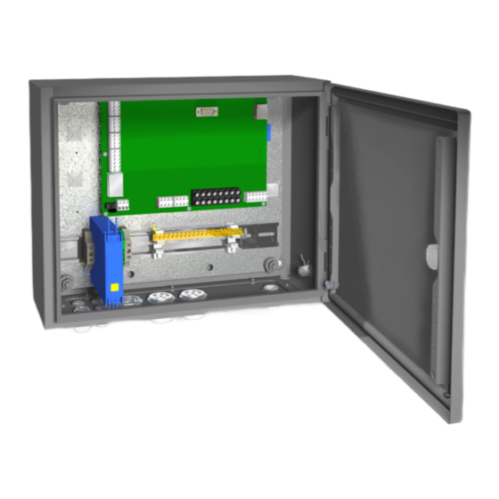
Page 8: Stainless Steel Enclosure
8 mm holes as shown in the figure, or sus- blind plugs and can be retrofitted); and four cable inlets pended in mounting braces (option SPM 81444). The of type M16x1.5 (C) for digital in/RPM/Ethernet cables, hole distance is 340 x 340 mm. Distances with mounting cable diameter 5 to 8 mm. -
Page 9: Power Supply
± 10%, no excessive transients). See the figure beside for con- nection to mains power terminals. Read the Safety Precautions on page 2 before performing electrical installation. If you are in doubt, please contact your local SPM representative before installing the equipment. •... -
Page 10: Electrical Installation
DO, for connection to PLC or via external ing circuits are running. The indicator, COM (5), is blinking relays to machine stop, external warning lamp, etc. when the unit communicates via Ethernet. – 8 – SPM 71930 B... -
Page 11: Bearing Monitoring
The transducer inputs have screw terminals (1) for coaxial cables with connector SPM 12775. Mounting of the con- nector set SPM 12775 is described on next page. The screw terminals are numbered 30 to 37. The cabinet has two cable inlets (3) of type M32 with rub- ber insert for up to 6 measuring cables, cable diameter 5 mm (IP65). -
Page 12: Preparation Of The Coaxial Cable
Cut the cable to length. Slide the crimp ferrule A onto the cable. Cut and strip the cable with a coaxial wire stripper (SPM 81052) as shown in figure 1. Mounting the Connector Push the core tube B over the inner conductor and against the dielectric, with all strands of the inner conductor inside the tube (see figure 2). -
Page 13: Vibration Monitoring
+ (A) – (B) push-in on the circuit board. See the figure beside for proper connection. Ground transducer type shield to Recommended transducers are SPM SLD144 or IEPE (ICP ) type trans- ® Protecive Earth Rail ducers with voltage output. DuoTech accelerometers type SLC144 for ®... -
Page 14: Connection Of Digital Inputs, Di / Rpm
14 mm spanner. Power Supply A red status indicator on the circuit board, next to the terminal Connection of PLC / DCS to DI/RPM input block, lights when a DI/RPM channel is active. – 12 – SPM 71930 B... -
Page 15: Connection Of Analog Inputs, Ai
Protective source. Check with a voltage tester to ensure that earth rail the unit is voltage free. • Mount terminal blocks (option SPM 93380) on the DIN rail (1). • Drill holes and mount suitable cable inlets on the flange. -
Page 16: Connection Of Digital Outputs, Do
A red status indicator on the circuit board, next to the terminal block, lights when a DO channel is active. Max. 1 A, 36 V DC Power Supply Connection to PLC / DCS (DO 1) – 14 – SPM 71930 B... -
Page 17: Sd Memory Card
Unit communicates with the LinX computer. and support). LinX is the communication software han- • The OP indicator (5) will light when the measuring dling all messages between the Condmaster database circuits are operating. and the Intellinova System Units. – 15 – SPM 71930 B... -
Page 18: Wireless 3G Router (Ins 12 W)
Connection: SMA female (main and GPS) Temperature Operating: – 40 to +70ºC Storage & transport: – 40 to +85ºC Electrical specification: 2 x SIM slots (3 volts SIM Degree of protection: IP 40 supported) – 16 – SPM 71930 B... -
Page 19: Technical Specifications Ins12/ Ins12 W
This product must be disposed as electronic waste and is marked with a crossed-out wheeled bin symbol in order to prevent it being discarded with household waste. When once the life cycle of the product is over You can return it to Your local SPM representative for correct treatment, or dispose it together with your other electronic waste.
Need help?
Do you have a question about the Intellinova Compact and is the answer not in the manual?
Questions and answers