
Subscribe to Our Youtube Channel
Related Manuals for SPM VibChecker


Summary of Contents for SPM VibChecker
- Page 1 make MAINTENANCE A PR OFI T A BLE PART OF YOUR v i b r a t i o n m o n i t o r i n g t o g o ™ P R O D U C T I O N v i b c h e c k e r .
- Page 2 SPM Instrument AB • Box 504 • SE-645 25 Strängnäs • Sweden Technical data are subject to change withput notice. Tel + 46 152 225 00 • info@spminstrument.se • www.spminstrument.com ISO 9001 certified. © Copyright SPM 2019-04 72220 B Rev.0...
-
Page 3: Table Of Contents
ISO 10816 Part 2 ....................29 ISO 10816 Part 3 ....................30 ISO 10816 Part 4 ....................31 Technical specifications ..............32 VibChecker VC200/250 ..................32 Accessories ...................... 32 Maintenance and calibration ............33 Maintenance ....................33 Calibration ...................... 33... - Page 5 Document Outline This User Guide contains useful information about the VibChecker, beginning with general infor- mation about instrument parts, user interface, battery and settings. This document also describes the hands-on use of the instrument, and how to confirm and evalu- ate measurement results.
-
Page 6: Introduction
VibChecker is designed as a maintenance aid. In accordance with the international standards, it measures vibration severity over the frequency range 10 to 1000 Hz. It allows a practical classification of machine condition in relative terms: good, acceptable, just tolerable, or bad. -
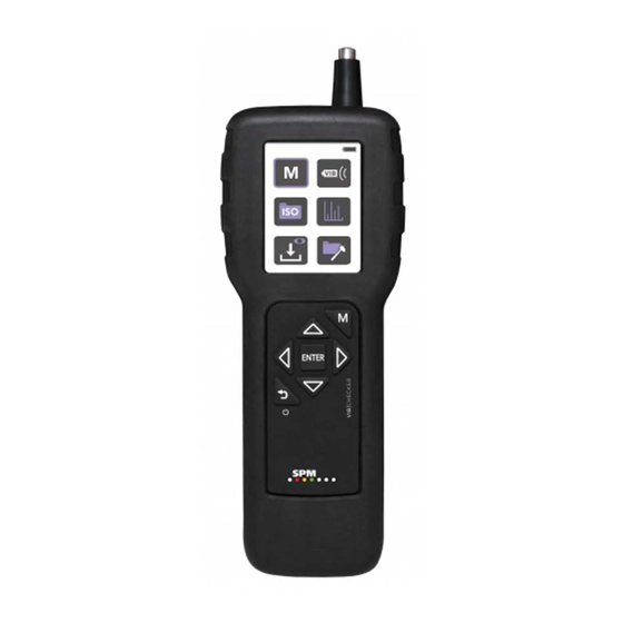
Page 7: Instrument Overview
The instrument has a built-in probe sensor (A). The external sensors with magnets TRM100, TRM120, and all types of SPM vibration sensor series SLD for permanent installation can also be used, connected to the sensor input (G). It is push-key controlled and basic measurement setup information is entered manually. -
Page 8: Displays And Icons
Displays and icons Main display Vibration measurement Sensor settings Spectrum settings ISO setup View stored readings General settings Navigation keys Confirm setting/Save reading Measure vibration levels (from anywhere in the menu structure) Go back one step (from anywhere in the menu structure) - Page 9 General settings Display contrast and Vibration quantity settings screensaver settings Units of measurement About Factory reset Date and time...
- Page 10 Vibration measurement ISO settings Condition status Measurement value Alternative value(s) View spectrum Save result to and time signal memory Spectrum analysis RPM, manual Measurement Spectrum Markers 1X-5X input Zoom in Step Step Move Move left right left right Zoom out...
-
Page 11: Battery
The instrument is powered by a lithium-ion battery, which is charged using a charger connected to the instrument’s USB communication output (or other USB output with the specifications 5V/500 mA). Please note that the instrument must be sent to a certified SPM Do not replace the battery! service and calibration partner for replacement of a discharged battery. -
Page 12: Start Up
Settings and instrument functions are selected using the arrow and ENTER keys (B). For all VibChecker versions, measurement is started manually from the Measurement display, which is opened by pressing the MEASURE key (C) from anywhere in the menu structure. -
Page 13: Settings
Settings Default settings Below is a summary of the main instrument settings and their respective factory default values: ISO standard = OFF (no condition evaluation will take place) ISO 10816 default settings = PART 3, GROUP 1, SUPPORT Rigid ISO 2372 default settings = CLASS 1, RPM 1500 Vibration quantity = VEL (velocity) Amplitude units = Velocity rms and Peak Units = Metric, Hz, vibration amplitude in g turned off... - Page 14 Display contrast and screensaver timeout To set the display contrast and the amount of idle time that should elapse before the screensaver is activated: A Main display 1. Go to the Main display (A). 2. Use the arrow keys to navigate to the General Set- tings icon (B), then press ENTER.
- Page 15 VEL (for more informa- will take place. tion, see section ‘Vibration quantity and amplitude units’). VibChecker bases condition evaluation on ISO rec- ommendations, with the exception that good and acceptable condition are both evaluated as green. A Main display...
- Page 16 Vibration quantity and amplitude units The selected vibration quantity (acceleration, velocity, or A Main display displacement) affects the unit for the result shown in the Measurement display as well as the spectrum and time signal unit. The default setting is Velocity (VEL). To set the vibration quantity: General settings 1.
- Page 17 Spectrum settings By activating the ‘AVERAGE’ parameter, VibChecker will perform four measurements, and then display an average of the measurement results. To set a number of spectrum lines: 1.
- Page 18 Reset A Main display To perform an instrument reset back to factory settings: 1. Go to the Main display (A). 2. Use the arrow keys to navigate to the General Set- tings menu (B), then press ENTER. General settings 3. In the General settings display, select the Reset icon (C) and press ENTER.
-
Page 19: Using External Sensors
Using external sensors VibChecker can be used with all accelerometers of type IEPE (ICP ) with voltage output. ® To configure VibChecker for measurement with an external vibration sensor: 1. Connect the sensor to the input connector (mini coax). 2. Go to the Main display (A). -
Page 20: Bias Voltage
Bias voltage When measuring vibration with external sensors, a bias voltage check will automatically be made to check the quality of the signal transmission between sensor and instrument. Part of your signal will be lost in a poor sensor line, so your measuring results will be incorrect. If a measurement is made with a poor sensor line, the instrument will display Bias error. -
Page 21: Vibration Severity Measurement
(peak) or as the total movement in both directions (peak to peak). Displacement is expressed in micrometers. VibChecker always measures an acceleration signal, which is integrated to obtain the velocity, and double-integrated to derive displacement. Both acceleration and speed are constantly changing. One can measure a peak value of either, but a mean value often gives a better indication of the forces involved in the movement. -
Page 22: Built-In Sensor With Probe
Built-in sensor with probe Measuring points for the built-in probe should be clearly marked. Always measure in the same spot. The probe tip is spring loaded and moves within a sleeve of hard rubber. To maintain a steady pressure on the tip, press the probe tip against the measuring point until the rubber sleeve is in contact with the surface. -
Page 23: Measurement
1. In the Main display (A), select the Measure icon (B) and press ENTER. The Measurement display opens, showing the most recent reading. 2. For a new measurement, point the VibChecker straight at the measuring point and press the probe tip until the rubber sleeve is in contact with the surface (or connect the external sensor). -
Page 24: Recording Readings For Follow-Up
Overrange warning If a measurement is made that exceeds the instrument’s measuring range, VibChecker will indicate an ‘Over- range’ error and the reading will not be accepted. Recording readings for follow-up VibChecker The VibChecker follow-up form provides space for follow-up form... -
Page 25: Storing Measurement Results
4. To return to the Measurement display, press the BACK key. The stored measurement results (excluding spectrum) can be transferred from VibChecker to a Microsoft Excel file using a downloadable SPM program (http://downloads.spminstru- ment.com). The data in the Excel file can be imported into a CMMS or other software for follow-up. -
Page 26: Spectrum Analysis
Spectrum analysis The purpose of a spectrum is to reveal line patterns associated with machine faults. VibChecker generates an FFT spectrum for pattern recognition. Spectrum display To view a spectrum: 1. In the Measurement display (A), press the RIGHT arrow key. -
Page 27: Rpm, Manual Input
RPM. In the spectrum, a red marker will appear at the RPM frequency entered here (C). VibChecker accepts up to 60 000 RPM. 3. Press ENTER to save and return to the Spectrum display where the marker can be seen, or press the BACK arrow key to return to the Spectrum display without saving RPM or setting a marker. -
Page 28: Time Signal Analysis
Time signal analysis In the time signal, the analog electrical output from the sensor is digitized, showing how vibration changes over time. The time domain signal can be a useful complement to spectrum analysis to reveal valuable additional information on machine condition, especially for troubleshooting of gearboxes and low-speed ap- plications (<100 RPM). -
Page 29: Iso 2372
6 are used for heavy reciprocating prime movers and machines which are intended to vibrate, such as vibrating screens. VibChecker is programmed with the ISO limit values and will evaluate the measuring result, provided the ISO machine class number is input in the ISO setup display. On the instrument, a green condition indicator will be shown for good and acceptable ISO values, a yellow indicator for just tolerable, and a red one in cases of unacceptable values. -
Page 30: Definition Of Machine Classes According To Iso 2372
Definition of machine classes according to ISO 2372 The following text is a quotation from ISO 2372 (1974, E, page 6, Annex A). This ISO recommendation has also been published as British Standard (BS 4675, part I). A similar vibration classification of industrial machinery can be found in VDI 2056. -
Page 31: Iso 10816
1000 Hz. Machine condi- tion evaluation according to the ISO 10816 standard requires a correct classification of the monitored machine. VibChecker covers ISO 10816 Parts 2, 3, and 4 > 600 RPM. ISO 10816 Part 2 In case the machine you want to monitor is a ‘large land-based steam turbine generator set in excess... -
Page 32: Iso 10816 Part 3
ISO 10816 Part 3 Part 3 treats most of the common industrial machines and is divided into four groups. Further criteria for Part 3 are the rigidity of the foundation and the rotational speed. Concrete foundations are rigid, every thing else falls under flexible. The RPM affects the lower measuring range as well as the limit values. Group 1 Evaluation zone boundaries for machines of Group 1: Large machines with rated power above 300 kW and not more than 50 MW;... -
Page 33: Iso 10816 Part 4
ISO 10816 Part 4 Part 4 is limited to ‘Gas turbine driven sets excluding aircraft derivates’. The standard also states a power output of at least 3 MW. Evaluation zone boundaries based on bearing housing/pedestal vibration velocity, valid for shaft rota- tional speed 3000 RPM to 20 000 RPM. -
Page 34: Technical Specifications
Technical specifications VibChecker VC200/250 Frequency range: 10 to 1000 Hz Readings: RMS / peak / peak-to-peak Measuring range, (sinus signal and 100 mV/g accelerometer): Velocity RMS 100 mm/s (4 ips) at 80 Hz Acceleration RMS 100 m/s (10 g) at 10-1000 Hz... -
Page 35: Maintenance And Calibration
Once the life cycle of the product is over you can return it to your local SPM representative for correct treatment, or dispose of it together with your other electronic waste. - Page 36 0.7 1.1 1.8 1.8 2.8 4.5 0.5 0.7 1.15 1.1 1.8 2.8 0.3 0.5 0.7 SPM Instrument AB • Box 504 • SE-645 25 Strängnäs • Sweden • Tel +46 152 225 00 • info@spminstrument.se • www.spminstrument.com © Copyright SPM 2019-01 VC200/250...
- Page 37 0.11 0.18 0.28 0.07 0.11 0.18 0.02 0.03 0.04 0.01 0.02 0.03 0.04 0.07 0.11 SPM Instrument AB • Box 504 • SE-645 25 Strängnäs • Sweden • Tel +46 152 225 00 • info@spminstrument.se • www.spminstrument.com © Copyright SPM 2019-01 VC200/250...
Need help?
Do you have a question about the VibChecker and is the answer not in the manual?
Questions and answers