Still FXV 14 N Original Instructions Manual
Pallet stacker
Hide thumbs
Also See for FXV 14 N:
- Original instructions manual (146 pages) ,
- Original instructions manual (50 pages)

Related Manuals for Still FXV 14 N


Summary of Contents for Still FXV 14 N
- Page 1 Original instructions Pallet stacker FXV 14 N FXV 16 N 1537 1538 2376 2377 11748011551 EN - 02/2021 - 09...
- Page 3 Preface Address of manufacturer and contact details STILL GmbH Berzeliusstraße 10 22113 Hamburg, Germany Tel. +49 (0) 40 7339-0 Fax: +49 (0) 40 7339-1622 Email: info@still.de Website: http://www.still.de 11748011551 EN - 02/2021 - 09...
-
Page 5: Table Of Contents
Table of contents Introduction Your industrial truck ........... General . - Page 6 Table of contents Overviews Overview ............General view .
- Page 7 Table of contents Drive program ............Joystick function (option) .
- Page 8 Table of contents Transporting the truck in the lift ..........Driving on loading bridges .
- Page 9 Table of contents Lift mast ............Cleaning and lubricating the chains.
-
Page 11: Introduction
Introduction... -
Page 12: Your Industrial Truck
Introduction Your industrial truck Your industrial truck General The truck described in these operating instruc- tions corresponds to the applicable standards and safety regulations. If the truck is to be operated on public roads, it must conform to the existing national regula- tions for the country in which it is being used. -
Page 13: Ce Labelling
Introduction Your industrial truck CE labelling The manufacturer uses CE labelling to indi- cate that the truck complies with the standards and regulations valid at the time of marketing. The supplied EC declaration of conformity confirms this. The CE labelling is attached to the nameplate. -
Page 14: Ec Declaration Of Conformity
Introduction EC declaration of conformity EC declaration of conformity Declaration STILL GmbH Berzeliusstrasse 10 22113 Hamburg GERMANY We declare that the machine Industrial truck according to these operating instructions Model according to these operating instructions conforms to the latest version of the Machinery Directive 2006/42/EC. -
Page 15: Identification Label
Introduction Identification label Identification label NOTE Indicate the serial number for all technical en- quiries. Model Manufacturer Serial number Year of manufacture Unladen weight (without battery) in kg Maximum battery weight Minimum battery weight (for a lithium-ion battery, the weight of the ballast container is included) Additional weight (ballast weight) in kg Nominal motor power (kW) -
Page 16: Eco-Design Requirements For Electric Motors And Variable Speed Drives
Eco-design requirements for electric motors and variable speed drives Internet address and QR code The information can be accessed at any time by pasting the address https://m.still.de/vdma in a web browser or by scanning the QR code. Eco-design requirements for electric motors and variable... -
Page 17: Spare Parts List
Spare parts list The spare parts list can be downloaded by en- tering the address https://sparepartlist.still.eu into a web browser or by scanning the QR code displayed to the side. When the web page is open, please type in... -
Page 18: Proper Usage
Introduction Proper usage Proper usage The truck described in these operating instruc- The purpose of obtaining these permissions in tions is suitable for lifting, transporting and advance is to limit danger as far as possible. stacking loads. The capacity label specifies the maximum The truck should only be used for the purpo- load that can be raised. -
Page 19: Unauthorised Use
Introduction Unauthorised use Unauthorised use Any danger caused as a result of unauthor- Transporting people is prohibited. ised use becomes the responsibility of the op- The forklift truck should not be used in areas erator or driver and not that of the manufactur- where there is a risk of fire, explosion or corro- sion, or in areas that are particularly dusty. - Page 20 Introduction Disposing of components and batteries 11748011551 EN - 02/2021 - 09...
-
Page 21: Safety
Safety... -
Page 22: Safety Regulations
Safety Safety regulations Safety regulations Regular checks and technical inspections These operating instructions, which come with ● the truck, must be communicated to all those Recycling of lubricants, oils and batteries ● concerned and in particular to personnel re- Residual risks. ●... -
Page 23: Safety Regulations For Handling Consumables
Safety Safety regulations for handling consumables Safety regulations for handling consumables Permissible consumables Refer to the maintenance data table for the WARNING permissible substances necessary for opera- Consumables can be dangerous. tion. It is necessary to follow the safety regulations when handling these substances. -
Page 24: Hydraulic Fluid
Safety Safety regulations for handling consumables Hydraulic fluid WARNING ENVIRONMENT NOTE During operation of the forklift truck, hy- draulic fluids are pressurised and are Hydraulic fluid is a water-polluting substance! hazardous to your health. Always store hydraulic fluid in containers com- –... -
Page 25: Disposal Of Consumables
Safety Safety regulations for handling consumables Disposal of consumables Any spillage of fluids such as hydraulic oil, ● ENVIRONMENT NOTE brake fluid or gear lubricant oil must be im- mediately soaked up with an oil-binding Materials that have to be disposed of following agent. -
Page 26: Emissions
Safety Emissions Emissions Noise emission values Calculated during the test cycle performed in NOTE accordance with standard EN 12053. Lower or higher noise values may occur when Acoustic pressure level in the driver's com- using industrial trucks, e.g. due to the mode of partment operation, environmental factors and other sources of noise. -
Page 27: Residual Dangers, Residual Risks
Safety Residual dangers, residual risks Residual dangers, residual risks Falling, tripping etc. when moving on the in- Despite all operational precautions and com- ● dustrial truck, especially in the wet, with pliance with standards and rules, the possibili- leaking consumables or icy surfaces. ty of additional risks when using the truck can- Loss of stability due to the load being unsta- not be entirely excluded. -
Page 28: Definition Of Responsible Persons
Safety Definition of responsible persons Definition of responsible persons Operating company The operating company is the natural or legal The operating company is responsible for the person or group who operates the truck or on scheduling and correct performance of regular whose authority the truck is used. - Page 29 Safety Definition of responsible persons Prohibition of use by unauthorised per- When leaving the truck, the driver must secure it against unauthorised use. sons The driver is responsible for the truck during working hours. He must not allow unauthor- ised persons to operate the truck. 11748011551 EN - 02/2021 - 09...
-
Page 30: Safety Tests
Safety inspection based on time and ex- traordinary incidents The operating company (see chapter entitled "Definition of responsible persons") must en- STILL GmbH Hamburg sure that the truck is checked by a specialist at least once a year or after noteworthy inci- Regelmäßige Prüfung dents. -
Page 31: Overviews
Overviews... -
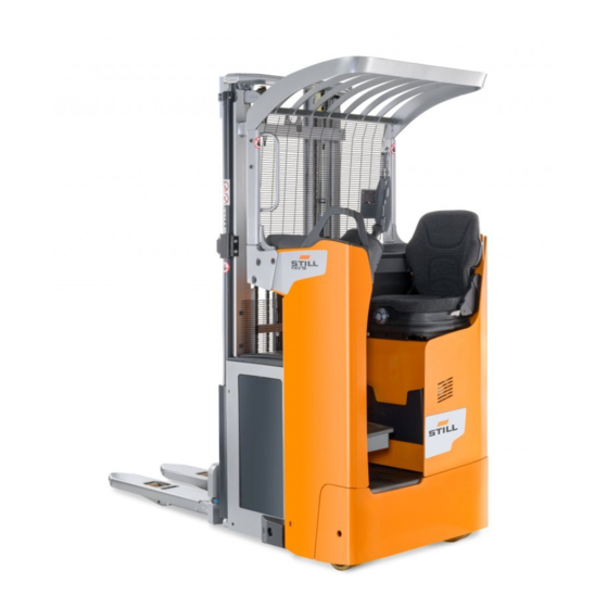
Page 32: Overview
Overviews Overview Overview General view Overhead guard Stabiliser wheel Protective screen Operator presence pedal Control module Battery compartment Seat Forks Lift cylinder Load wheels or bogies Platform Mast Drive wheel Emergency off switch 11748011551 EN - 02/2021 - 09... -
Page 33: General View Of The Technical Compartment
Overviews Overview General view of the technical compartment Pump-motor unit Fuses Tank Horn ES30-24 steering unit Traction motor 11748011551 EN - 02/2021 - 09... -
Page 34: Operating And Display Devices
Overviews Operating and display devices Operating and display devices Driver's compartment Control unit or joystick (depending on option Display selected) Control button (Steering Knob device) Emergency off switch Steering wheel Switch key (or electronic key) Handle for stepping on and off the truck 11748011551 EN - 02/2021 - 09... -
Page 35: Electronic Key (Option)
Overviews Operating and display devices Electronic key (option) Switch ON (operating mode) Key fault or incorrect code Switch OFF and awaiting code Time delay of automatic switch-off Programming mode active Operation Enter Status of LEDs Comments ○ red off ● continuous (by de- green (1) (correct PIN) * 1 2 3 4 5 #... - Page 36 Overviews Operating and display devices PROGRAMMING (truck switch OFF only (2)) To reactivate the default Restoring the ini- administrator code tial administrator (00000000), please con- code tact your agent or nearest dealer. Power switches off auto- ● red flashing ● green matically after 10 mi- Activating the au- flashing (5) (5 seconds...
-
Page 37: Display Operating Unit
Overviews Operating and display devices Display operating unit Operator presence indicator light Settings menu Battery indicator light Load Management and Drive wheel position Temperature indicator light menu Settings indicator light Status menu Warning indicator light Display of the operating time of the truck Drive programme indicator light Display of the battery charge Activity indicator light... -
Page 38: Markings
Overviews Markings Markings Location of markings Identification label Capacity label Brand label Never touch with hands label Regular safety inspection of the truck label Mast safety label Danger instructions label. Consult operating Slinging label. Consult operating instructions instructions Model label 11748011551 EN - 02/2021 - 09... -
Page 39: Serial Number
Overviews Markings Serial number xx xxxx x xxxxx NOTE Indicate the serial number for all technical en- quiries. The serial number contains the following infor- mation: 1 Production location 2 Type 3 Year of production 4 Count number 7090_921-004 11748011551 EN - 02/2021 - 09... - Page 40 Overviews Markings 11748011551 EN - 02/2021 - 09...
-
Page 42: Technical Description
FXV 16 N: 1600 kg in pallet stacker mode tor that positions the turntable. ● FXV 14 N with initial lift: 1400 kg in pallet ● The steering motor is controlled by a variable stacker mode and 2000 kg in pallet truck speed transmission. - Page 43 Technical description Optional equipment available (this list is not NOTE exhaustive): The operating instructions can be found in the Electronic key ● document holder, located on the technical Cold store (-35°C) ● compartment door. Document holder ● Steering knob ● Joystick ●...
-
Page 44: List Of Checks Prior To Start-Up
List of checks prior to start-up List of checks prior to start-up – Damaged or missing stickers must be re- WARNING placed in compliance with the marking posi- Damage or other defects on the forklift truck or at- tion table. tachments (special equipment) can result in acci- dents. -
Page 45: Starting Up
Starting up Starting up NOTE Check that no controls are activated before ● starting the truck. Check that the battery hood is closed. ● Check that the battery is locked. ● – Check that the battery is connected. – Check that the battery compartment hood is closed and locked correctly. -
Page 46: Checks And Actions Prior To Commissioning
Checks and actions prior to commissioning Checks and actions prior to commissioning Checking the emergency off switch To check the operation of the emergency off switch, proceed as follows: – Drive the truck – Press the emergency off switch (1) The truck stops immediately. -
Page 47: Checking The Horn
Checks and actions prior to commissioning Checking the horn The horn is located on the rear side of the control module. To check the operation of the horn, proceed as follows: – Press the button (1) on the control module The horn sounds. -
Page 48: Truck Operating Instructions
Truck operating instructions Truck operating instructions The trucks are designed for indoor and out- Speed must be reduced when moving over door use in non-hazardous atmospheres. The obstacles to prevent the truck from becoming temperature should be between -10°C and unbalanced and vibrations in the operator's +45°C and the relative humidity of the air less arms. - Page 49 Truck operating instructions WARNING CAUTION Driving safety guidelines: Risk of injury – The driver must drive slowly around corners and Before using a side access truck, check that the bat- when entering narrow passageways. tery is correctly locked. – The driver must always maintain a safe braking distance from vehicles or people in front of him.
-
Page 50: Stepping On/Off The Truck
Stepping on/off the truck Stepping on/off the truck WARNING Risk of falling, tripping or slipping when stepping on/off the truck. Use the handle (1) and the seat (2) to help when stepping on/off the truck. – Hold the handle (1) with one hand –... -
Page 51: Operation Of Operator Presence Detection
Operation of operator presence detection Operation of operator pres- ence detection The truck is equipped with two operator pres- ence detectors: The chair (2) ● The presence pedal (1) ● These two components are truck safety devi- ces. First, the forklift operator must sit on the chair (2). - Page 52 Operation of operator presence detection CAUTION Disabling of controls If the operator presence pedal is released when moving: - The truck brake is automatically activated - The controls no longer work 11748011551 EN - 02/2021 - 09...
-
Page 53: Driver's Compartment Settings
Driver's compartment settings Driver's compartment settings Adjusting the seat The seat is equipped with an operator pres- ence detector. The operator must adjust his weight by incre- ments of 10 kg to trigger this detection. Proceed as follows: – Sit on the seat –... -
Page 54: Seat Heater Option
Driver's compartment settings Seat heater option The driver's seat may be equipped with the seat heater option. The heater turns on when the operator's pres- ence on the seat is detected. To activate the heater, proceed as follows: – Sit on the seat –... -
Page 55: Using The Display-Operating Unit
Using the display-operating unit Using the display-operating unit Selection buttons The operator selects the menus using the four selection buttons: The Blue Q button (1) to select Blue Q ● mode, hare mode or tortoise mode The left arrow button (2) to scroll left ●... - Page 56 Using the display-operating unit – Sit on the seat The light indicating the operator's presence on the seat (1) is replaced by the light indicat- ing the operator's presence on the pedal (2), which flashes. – Press the operator presence pedal with ...
- Page 57 Using the display-operating unit Managing battery charging The operating unit shows the battery charge level. The operator can refer to the battery icon (1) or (2). The number of bars shown indicates the bat- tery charge level. From 0 to 20%: 1 bar ●...
- Page 58 Using the display-operating unit Drive program The drive program light (1) is permanently illu- minated when a travel mode is selected. There are three different drive modes: Tortoise mode (2) ● Hare mode (3) ● Blue Q mode (4) ●...
- Page 59 Using the display-operating unit Settings menu It is possible to access different settings through the Settings menu. – Select the Settings menu (1) This menu allows access to a drop-down menu (2) consisting of: Language ● Unit ● Date format ●...
- Page 60 Using the display-operating unit Start-up screen In addition to the various menus and lights mentioned above, additional data is available: The Truck status menu (1) displays the ● truck menu The hourglass icon (2) indicates the operat- ● ing time of the truck The clock icon (3) indicates the time and ●...
-
Page 61: Driving Safety Guidelines
Driving safety guidelines Driving safety guidelines Behaviour when driving Never sit on the dashboard to drive the ● truck Operators must obey the same rules within The truck must not be used as a stepladder ● the plant as on the road. They must drive at The truck is not designed to transport peo- ●... -
Page 62: Driving
Driving Driving Defining directions Names used in the text refer to the component installation position with respect to the driver's compartment. Reverse travel (1) ● Forward travel (3) ● To the right (4) ● To the left (2) ● The load is positioned at the rear. -
Page 63: Braking
Driving Forward travel – Using your thumb, push the drive switch to the left (2) to travel forwards (opposite fork direction). – When the drive switch is released, the truck brakes electrically. Reverse travel – Using your thumb, push the drive switch to the right (1) to travel backwards (fork direc- tion). -
Page 64: Horn
Driving Braking by reversing the drive direction – Move the drive direction switches (2) or (3) in the opposite drive direction. Braking by releasing the drive switch – While travelling, completely release the drive switch. The brake is automatically activated. The truck is immobilised. -
Page 65: Drive Program
Driving Drive program The indicator light (1) is on during operation of the truck. The shape of the indicator light indi- cates the selected program. The truck is equipped with three different drive programs: Hare mode (3) ● BlueQ mode (4) ●... -
Page 66: Joystick Function (Option)
Driving Joystick function (option) The truck may be equipped with a joystick in place of the control unit. The operation is therefore different. NOTE Always operate the joystick slowly, as the truck reacts immediately. Abrupt starts, brak- ing or reversal of drive direction must be avoi- ded at all costs. -
Page 67: Steering Knob Option
Driving Rear of the joystick The rear of the joystick is used to: Sound the horn ● Raise or lower the load arms ● Horn – Press the button (5) on the joystick. Raising the load arms (initial lift) –... - Page 68 Driving – Move the turning knob to the left (anti-clock- wise) (2) to turn to the right – Move the turning knob to the right (clock- wise) (2) to turn to the left 11748011551 EN - 02/2021 - 09...
-
Page 69: Using The Truck On A Slope
Driving Using the truck on a slope NOTE Incorrect use of the truck on a slope is not rec- ommended. It places particular stress on the traction motor, brakes and battery. Slopes must be approached with great cau- tion: Never attempt a slope whose gradient is ●... - Page 70 Driving Travelling down slopes Always travel down slopes forwards. The load faces uphill. Without a load, we recommend that you de- scend a slope forwards. In all cases, you must travel at a very low speed and brake gradually. DANGER Danger of death and/or risk of serious damage to equipment...
-
Page 71: Operating The Fleetmanager™ Option
Operating the FleetManager™ option Operating the FleetManager™ option Description of the FleetManager option The FleetManager option allows you to control GSM: Global System for Mobile Communi- access to the truck. The option is a fleet man- cation agement system. Shock sensor You can access the system: Either by using a keypad This sensor allows you to record the shocks... -
Page 72: Commissioning A Truck Equipped With The Fleetmanager™ Option
Operating the FleetManager™ option Commissioning a truck equipped with the FleetManager™ option Commissioning a truck equipped with a keypad or an electronic key – Turn the switch key to start the truck. – Enter the PIN code on the keypad. The PIN code consists of five to eight digits. -
Page 73: Fleetmanager™ Option: Colour Code For The Leds
Operating the FleetManager™ option FleetManager™ option: Colour code for the LEDs The LEDs can have different statuses and dif- ferent colours. Below is the list of the most common messages and their meanings. Malfunction Cause Solution LED status Signal transmitter LED 1 LED 2 Reading device... - Page 74 Operating the FleetManager™ option Malfunction Cause Solution LED status Signal transmitter LED 1 LED 2 Flashes quickly Lit continuously A shock has oc- Reset the shock Red colour Green colour curred The truck is The truck is con- switched on but is nected via a Blue- not moving.
-
Page 75: Disconnecting A Truck Equipped With The Fleetmanager™ Option
Operating the FleetManager™ option Disconnecting a truck equipped with the FleetManager™ option NOTE Operators must not log off intentionally while driving. WARNING Access to the truck must be disabled. Unauthorised users are not allowed to use the truck. Disconnecting a truck equipped with a ... - Page 76 Operating the FleetManager™ option Disconnecting a truck equipped with an RFID reading device – Park the truck in a safe place. – Briefly place the RFID card or the RFID transponder (4) in front of the reading de- vice (3). The LED (1) lights up for a second (red col- our).
-
Page 77: Transporting Loads
Transporting loads Transporting loads Load handling safety rules WARNING Carefully observe the following instructions before picking up loads. Never touch or stand on moving parts of the truck (e.g. lifting device, pushing devices, work installations or devices for picking up loads). WARNING Take care not to trap hands or feet when operating the truck. -
Page 78: Transporting Pallets Or Other Containers
Transporting loads Transporting pallets or other con- tainers As a general rule, loading units must be trans- ported one by one (e.g. pallets). Transporting several loading units at a time is only author- ised: when the safety preconditions are fulfilled. ●... -
Page 79: Lift Control Elements
Transporting loads Lift control elements WARNING Risk of injury The safety instructions must be strictly adhered to. Do not touch or stand on moving parts (e.g. lifting de- vice, pushing devices, work installations, load lifting devices). CAUTION Risk of the load swinging and loss of stability Do not drive with a load in the raised position with- out load on the load arms. - Page 80 Transporting loads Base lift Lifting the load arms – Pull the control (2) downwards (D). The load arms are raised. Lowering the load arms – Push the control (2) upwards (C). The load arms are lowered. 11748011551 EN - 02/2021 - 09...
-
Page 81: Reading The Capacity Plate
Check that the pallet is in good condition. FXV 14/16 N capacity — without initial lift FXV 14 N: 1400 kg FXV 16 N: 1600 kg FXV 14/16 N capacity — with initial lift FXV 14 N: 1400 kg... -
Page 82: Progressive Stopping Of The Carriage In The Lower Position
Transporting loads 8: Mast capacity: 1600 kg with a height of ● 3000 mm (centre of gravity: 600 mm) 9: Maximum lift height: 210 mm with ● 2000 kg in pallet truck mode 10: Maximum capacity in pallet truck mode: ●... -
Page 83: Handling A Single Load
Transporting loads Handling a single load DANGER Risk of truck falling Do not stack the initial lift high. Before picking up a load Ensure that the load weight does not exceed the capacity of the truck. Refer to the nominal capacity specified on ●... - Page 84 Transporting loads Picking up a load from the ground – Use the initial lift to raise a load of up to 2000 kg several centimetres from the ground. Transporting a load DANGER Risk of accident There must be no one under or near the truck when the load is in the raised position.
- Page 85 Transporting loads CAUTION Risk of falling Do not touch nearby loads or loads positioned be- hind the truck. CAUTION Risk of accident Before you set down the load, ensure that no one is around the truck or the load. Stacking a load ...
- Page 86 Transporting loads Picking up a load at a height Proceed as follows: – Drive the truck to the required location. – Lower the load arms completely. – Lift the forks to the height of the pallet. – Carefully move the forks forward under the pallet.
-
Page 87: Driving Assistance System: Dynamic Load Control
Driving assistance system: Dynamic Load Control Driving assistance system: Dynamic Load Control Description of the Dynamic Load Control (DLC) The Dynamic Load Control function (DLC) is a system that assists when driving and using the truck. The forklift operator must remain vigilant un- der all circumstances and adhere to the truck capacity plate. -
Page 88: The No Dynamic Load Control (Dlc) Display
Driving assistance system: Dynamic Load Control CAUTION Risk of loss of warranty. The A unit (1) contains a battery. Only a technician approved by the After Sales Service Centre may change this battery. It is normally changed every two years or after 2000 hours of operation. CAUTION Risk of incorrect use of the truck. -
Page 89: Using Dynamic Load Control (Dlc) Version 1
Driving assistance system: Dynamic Load Control Using Dynamic Load Control (DLC) version 1 The Dynamic Load Control (DLC) option ver- sion 1 informs the forklift operator of: The maximum weight allowed on the forks ● (nominal load) when the maximum value is close or has been exceeded. - Page 90 Driving assistance system: Dynamic Load Control Example of reading a display with the Dy- namic Load Control (DLC) option version 1: load weight close to maximum values The weight of the load on the forks is 2000 kg (2). A tolerance of ± 50 kg applies. The dis- played weight takes this into account.
-
Page 91: Using Dynamic Load Control (Dlc) Version 3
Driving assistance system: Dynamic Load Control Using Dynamic Load Control (DLC) version 3 The Dynamic Load Control (DLC) option ver- sion 3 allows you to: Manage the residual capacity of the truck in ● relation to the load weight and the mast height Adjust the maximum speed of the truck in ●... - Page 92 Driving assistance system: Dynamic Load Control The weight of the load on the forks (4) is not displayed. The lift height measured (3) is 2.9 m. The maximum permitted height is 3.3 m (1) with a maximum load of 1400 kg (2). NOTE It may be necessary to update the weight.
- Page 93 Driving assistance system: Dynamic Load Control Example of reading a display with the Dy- namic Load Control (DLC) option version 3: weight of the load slightly exceeded The weight of the load on the forks is 1450 kg (6). A tolerance of ± 50 kg applies. The dis- played weight takes this into account.
-
Page 94: Rules For Using The Dynamic Load Control
Driving assistance system: Dynamic Load Control However, the operator can still continue lifting to free a load. To authorise this activity, he must proceed in the following manner: – Validate the message "Caution."" ""Capaci- ty exceeded" (1) using the confirmation but- ton (2). - Page 95 Driving assistance system: Dynamic Load Control Starting the truck NOTE When starting the truck, the forks must be in the lowered position. If the forks are in the raised position when starting the truck, the Dynamic Load Con- trol icon (3) is highlighted. A yellow triangle symbol (1) appears on the display.
- Page 96 Driving assistance system: Dynamic Load Control In the event of error code L354 The error code L354 (1) may appear on the display screen. It is therefore necessary to check that: Nothing is blocking the field between the ● two sensors The presence of an object may block it The sensors are clean...
-
Page 97: Cold Store Usage (Optional)
Cold store usage (optional) Cold store usage (optional) CAUTION Standard trucks risk being subject to significant dam- age if used in extreme conditions. Only trucks with the Cold Store option may be used inside cold storage. Specific oil designed for cold stores must be used. - Page 98 Cold store usage (optional) Parking The truck must be parked outside of the cold store. Parking inside the cold store could cause seri- ous damage to the electrical and mechanical equipment (seals, hoses, rubber and synthetic parts). CAUTION Do not leave discharged or unused batteries in the cold store.
-
Page 99: Parking The Truck
Parking the truck. Parking the truck. – Switch off the ignition (key or electronic WARNING key). Risk of injury – Press the emergency off switch. Never leave the truck with the load in the raised posi- tion. Restarting work Do not stop the truck on a slope. If absolutely neces- sary, secure the truck with wedges. -
Page 100: Handling The Battery
Handling the battery Handling the battery Battery type Trucks can be fitted with different types of bat- tery. Comply with the information indicated on your battery's type plate, as well as with its features. WARNING The weight and size of the battery influence the sta- bility of the truck. -
Page 101: Opening And Closing The Battery Hood
Handling the battery Parking the truck securely When the battery is being worked on, the truck must be parked safely. The truck can only be restarted when the covers and connectors have been put back in the operating position. Opening and closing the battery ... -
Page 102: Charging The Battery Using An External Charger
Handling the battery Charging the battery using an exter- nal charger CAUTION Deep discharging may damage the battery. – Charge the battery immediately. – Park the truck safely. – Before charging, check the condition of the battery cable and the charger cable. Re- place them if necessary. - Page 103 Handling the battery WARNING Explosive gases are generated during battery charg- ing. – Make sure that the area is well-ventilated. – Make sure that the battery hood remains open for the entire time the battery is charging. 11748011551 EN - 02/2021 - 09...
-
Page 104: Changing The Side Access Battery
Handling the battery Changing the side access battery DANGER Risk of trapping fingers It is advisable to wear gloves when changing the bat- tery. WARNING Risk of injury Safety shoes must be worn when changing the bat- tery. Before handling, ensure that there is nobody around the truck. - Page 105 Handling the battery – Place the connector on the battery cells. – Position the truck with extraction rollers or the roller frame (4) in the upright position next to the battery compartment on level ground. – Operate and pull the locking handle (2) in ...
- Page 106 Handling the battery – Lift the locking bar (3) until the battery is freed. – Pull the battery onto the truck with extrac- tion rollers or the roller frame. – Replace the battery. Remove the dis- charged battery and position a charged bat- tery on the roller frame.
- Page 107 Handling the battery – Carefully push the battery into the compart- ment. DANGER Risk of trapping fingers Push the battery from the rear side (A) of the battery. Take care not to trap your fingers by pushing from the top or the side of the battery. DANGER Risk of injury The battery is correctly positioned but is not yet...
- Page 108 Handling the battery – Lower and lock the handle (2) of the locking bar (3) in the direction indicated by the ar- row. The locking bar must be horizontal and must be right up against the stop (5). CAUTION Risk of locking the battery incorrectly The locking bar should not in any circumstances be positioned under or on top of the stop.
-
Page 109: Handling The Truck In An Emergency
Handling the truck in an emergency Handling the truck in an emergency Emergency lowering of the mast The emergency control (1) allows the mast to be lowered manually in the event of a prob- lem. This operation is to be performed as follows: –... -
Page 110: Truck Towing Procedure
Handling the truck in an emergency Truck towing procedure It is not possible to tow the truck with no elec- trical function. The electromagnetic brake re- mains in the closed position. Truck towing is authorised with a rigid connec- tion (tow bar) if the truck to be towed can no longer be braked. - Page 111 Handling the truck in an emergency – After towing, chock the truck to prevent it from moving. – To re-establish brake operation, unscrew and remove the two screws (1). – Refit the covers. WARNING It is essential that the covers are correctly refitted be- fore the machine is used.
-
Page 112: Handling The Truck In Specific Situations
Handling the truck in specific situations Handling the truck in specific situations Slinging the truck DANGER Danger of truck falling Only use slings and a hoist of sufficient quality. Check the weight of the machine (including battery) in order to choose a suitable device. Refer to the technical features. -
Page 113: Lifting The Truck
Handling the truck in specific situations Lifting the truck DANGER Danger of swinging Truck lifting must be performed carefully. For some work, it is necessary to lift the truck. – Lift the load arms. – Switch off the ignition and disconnect the battery connector. -
Page 114: Transporting The Truck In The Lift
Handling the truck in specific situations The truck must be suitably protected from the DANGER effects of the weather during transport and Danger of death. storage. Do not stand within the hoist's operating radius or To load or unload the truck, use an inclined below the lifted truck. -
Page 115: Maintenance
Maintenance... -
Page 116: General Maintenance Information
Maintenance General maintenance information General maintenance information General The following instructions contain all the infor- mation required for maintenance of your truck. Carry out the various maintenance work in compliance with the maintenance plan. This will ensure that your truck is reliable and in good working order and that the warranty re- mains valid. -
Page 117: Servicing And Maintenance Personnel Training And Qualification
Maintenance General maintenance information Servicing and maintenance personnel training and qualification Truck maintenance must only be carried out The person responsible for carrying out the in- by qualified and authorised personnel. spection must have sufficient knowledge and experience to be able to assess the condition The annual inspection for prevention of acci- of the truck and the efficiency of the protective dents at work must be carried out by a person... -
Page 118: Safety Guidelines For Maintenance
Maintenance Safety guidelines for maintenance Safety guidelines for maintenance Servicing and maintenance measures To avoid accidents during servicing and main- – Ensure that there is no risk of the truck tenance operations, take all necessary safety moving or starting up unexpectedly. For this measures. -
Page 119: Technical Data For Inspection And Maintenance
Maintenance Technical data for inspection and maintenance Technical data for inspection and maintenance Assembly Consumables/lubricants Capacities/adjustment values Minimum oil volume: 7.7 litres Hydraulic system Hydraulic oil Maximum oil volume: 8.3 litres Transmission gear Transmission gear oil 0.98 l Traction motor (3 kW) 1F1 fuse Power: 300 A, quantity: 1 Steering unit ES30–24... -
Page 120: Recommended Lubricants
Maintenance Recommended lubricants Recommended lubricants SAE 85W 90 API GL4 CAUTION Damage to equipment if non-recommended lubri- Aerosol can for chains cants are used. Only use recommended lubricants. Only the lubri- Standard chain spray cants listed below are approved by the manufacturer. Do not mix lubricants. -
Page 121: Accessing The Technical Compartment
Maintenance Accessing the technical compartment Accessing the technical com- partment In order to perform maintenance on various truck components, it is necessary to access the technical compartment. – Immobilise the truck – Lower the forks – Switch off the truck (key or electronic key) –... - Page 122 Maintenance Accessing the technical compartment – Open the technical compartment door (2) You must close the technical compartment af- ter the operation is finished. – Close the door (2) CAUTION Risk of trapping fingers. Take care not to trap your fingers between the door and the chassis.
-
Page 123: 1000-Hour Maintenance Plan
Maintenance 1000-hour maintenance plan 1000-hour maintenance plan Depending on the application, environmental conditions and driving style, the following proce- dures should be carried out every 1000, 2000, 3000, 4000, 6000, 7000, 8000 and 9000 hours Preparation Clean the truck Check the error codes using the diagnostic tool Chassis and equipment Check the condition of the forks Check the electromagnetic brake and ensure that it is working correctly... -
Page 124: 5000-Hour Maintenance Plan
Maintenance 5000-hour maintenance plan 5000-hour maintenance plan Depending on the application, environmental conditions and driving style, the following proce- dures should be carried out every 5000 and 10,000 hours Information Carry out all 1000-hour maintenance work Hydraulics Drain the hydraulic oil 10,000-hour service plan Depending on the application, environmental conditions and driving style, the following proce- dures should be carried out every 10,000 hours... -
Page 125: Chassis, Bodywork And Fittings
Maintenance Chassis, bodywork and fittings Chassis, bodywork and fittings Cleaning the truck Cleaning instructions – Park the truck. – Press the emergency off switch. CAUTION Electrical hazards The battery must always be disconnected during cleaning procedures. Washing the outside of the truck ... - Page 126 Maintenance Chassis, bodywork and fittings NOTE Only use dry cleaning products ● Do not remove the cowlings ● – Clean the electrical installations with a non- metal brush and dry with lightly compressed air. After washing – Carefully dry the truck (e.g. with com- pressed air).
-
Page 127: General Information On Battery Maintenance
Maintenance Chassis, bodywork and fittings General information on battery maintenance DANGER NOTE Risk of injury The discharge indicators used to check the ● Before carrying out any operations on the electric in- battery must also be suitable for the type of stallation, turn the truck power supply off. -
Page 128: Checking The Condition Of The Forks
Maintenance Chassis, bodywork and fittings Checking the condition of the forks – Check that the forks (1) show no signs of deformation, splits, heavy wear or cracks. CAUTION Truck damage If the carriage is damaged, have it changed by the After-Sales Service Centre. -
Page 129: Steering And Wheels
Maintenance Steering and wheels Steering and wheels Checking the condition of the wheels – Raise the truck until the wheels are off the ground. – Check that the wheels rotate freely and re- move any objects that may prevent them from turning or may obstruct them. -
Page 130: Electrical Equipment
Maintenance Electrical equipment Electrical equipment Cleaning and blowing out the elec- trical components CAUTION Electrical hazards Always disconnect the battery connector before working on an electrical component. – Press in the emergency off switch. – Disconnect the battery connector. –... - Page 131 Maintenance Electrical equipment WARNING The electrolyte (diluted sulphuric acid) is poisonous and corrosive. – Always wear suitable protective equipment (indus- trial protection goggles, safety gloves) when work- ing on a battery. – Never wear a watch or jewellery when handling battery acid.
-
Page 132: Checking The Condition Of Cables, Terminals And The Battery Connector
Maintenance Electrical equipment Checking the condition of cables, terminals and the battery connector – Check that the cable insulation is undam- aged – Check that there are no signs of heat build- up in the connections – Check that the "+" and "-" output terminals are not sulphated (presence of white salt) –... -
Page 133: Hydraulic Systems
Maintenance Hydraulic systems Hydraulic systems Checking the hydraulic system for leaks – Switch off the truck and disconnect the bat- tery connector – Move the seat all the way forwards – Open the technical compartment door – Inspect the hydraulic system: pipes, hoses and connections between the pump unit and the cylinders –... - Page 134 Maintenance Hydraulic systems – Open the technical compartment door To ensure proper usage of the truck functions, the oil level must be between the minimum (3) and maximum (2) marks on the tank. – Remove the plug (1). If necessary, top up via the opening –...
-
Page 135: Lift Mast
Maintenance Lift mast Lift mast Cleaning and lubricating the chains NOTE NOTE If the lifting chain is too dirty, clean it. Use of high pressure liquid cleaning devices is not advisable. – Place a recipient underneath the lifting chain. DANGER –... -
Page 136: Checking The Protective Screen
Maintenance Lift mast – Fully lower the mast. – Undo the locknut (2) – Place the chains under slight tension by tightening the nut (1). – Retighten the locknut (2). CAUTION Risk of the equipment becoming worn or damaged. After this adjustment, check that the fork carriage does not reach the mechanical stop at the top of the mast during the maximum lift. - Page 137 Maintenance Lift mast DANGER Poor visibility The screen must be installed and correctly attached. Do not attach anything to the screen that could affect the visibility of the forks. When cleaning the fork carriage side, only clean the screen when the fork carriage is in the lowered posi- tion.
-
Page 138: Storage And Decommissioning
Maintenance Storage and decommissioning Storage and decommissioning Storage of truck Precautions should be taken if the truck must CAUTION not be used for a reasonably long period. The We recommend that you do not use a plastic sheet operations depend on the length of time it is as this encourages condensation to form. -
Page 139: Permanent Putting Out Of Commission (Destruction)
Maintenance Storage and decommissioning Permanent Putting Out of Commis- sion (Destruction) When scrapping the truck, it is necessary to: – Remove the various parts of the truck (cov- ers, battery, chains, motors etc.) – Sort out the components depending on their type: pipes, rubber components, lubricants, aluminium, iron etc. - Page 140 Maintenance Storage and decommissioning 11748011551 EN - 02/2021 - 09...
-
Page 141: Technical Specifications
Technical specifications... -
Page 142: Fxv 14N / 16N Datasheet
Technical specifications FXV 14N / 16N datasheet FXV 14N / 16N datasheet 11748011551 EN - 02/2021 - 09... - Page 143 Technical specifications FXV 14N / 16N datasheet FXV 14N / FXV FXV 14Ni / FXV DESCRIPTION 16Ni 1.1 Manufacturer STILL FXV 14N / FXV FXV 14Ni / FXV 1.2 Model type 16Ni Method of propulsion: Battery Battery battery, diesel, petrol, LPG, mains power...
- Page 144 Technical specifications FXV 14N / 16N datasheet 4.5 Extended mast height h4 (mm) 3364 3364 4.6 Initial lift h5 (mm) 4.7 Overhead guard height (cab) h6 (mm) 2378 2378 Seat height relative to the SIP/height of h7 (mm) 1024 1024 support (±5 mm) Load arm/ground height h8 (mm)
- Page 145 Technical specifications FXV 14N / 16N datasheet Main lift lowering speed when laden/unla- 0.343/0.342 0.343/0.342 den (±10%) Maximum gradient (0 kg, 1200 kg, 20/11/- 20/11/9 2000 kg) 5.9 Acceleration time (10 m) 6.1/5 6.1/5 Service brake electromagnetic electromagnetic FXV 14N / FXV FXV 14Ni / FXV DRIVE SYSTEM 16Ni...
-
Page 146: Fxv 14N / 16N Mast Types
Technical specifications FXV 14N / 16N mast types FXV 14N / 16N mast types Mast type Standard 1844S 2344S 2844S 3244S 3744S 4144S 4644S 1415 1665 1915 2115 2365 2565 2815 1490 1740 1990 2190 2440 2640 2890 1844 2344 2844 3244 3744... - Page 147 Index Oil Safety Information....13 Safety information for handling hydraul- Accessing the technical compartment. . . 111 ic fluid......14 Address of manufacturer.
- Page 148 Index Features......32 Lift control elements....69 FleetManager™...
- Page 149 Index Technical description....32 Transmission oil....110 Safety devices.
- Page 152 STILL GmbH 11748011551 EN - 02/2021 - 09...
Need help?
Do you have a question about the FXV 14 N and is the answer not in the manual?
Questions and answers