Still FM-X-10 Original Instructions Manual
Hide thumbs
Also See for FM-X-10:
- Original instructions manual (292 pages) ,
- Original instructions manual (360 pages)
Table of Contents
Advertisement
Quick Links
Advertisement
Table of Contents

Related Manuals for Still FM-X-10


Summary of Contents for Still FM-X-10
- Page 1 Original instructions Reach truck FM-X, FM-X N, FM-X W, FM-X EW, Lithium-ion FM-X-10 FM-X-12 FM-X-14 FM-X-17 FM-X-20 FM-X-20 HD FM-X-25 1900 1901 1902 1903 1904 1905 1906 1907 1908 1909 1910 1914 1915 1916 1917 1918 1919 1920 1921 1922...
- Page 3 Internet address and QR code The information can be accessed at any time by pasting the address https://m.still.de/vdma in a web browser or by scanning the QR code. 50988078001 EN - 11/2021 - 10...
-
Page 5: Table Of Contents
Table of contents Foreword Your truck ............General . - Page 6 Table of contents Changes and retrofitting ..........Modifications to the overhead guard and cabs .
- Page 7 STILL SafetyLight (variant) ........
- Page 8 Table of contents Applying the electromagnetic parking brake ........Steering .
- Page 9 Table of contents Operating the clamp locking mechanism (variant) with a joystick 4Plus ... . . Operating the clamp locking mechanism (variant) with the fingertip switch ..Picking up a load using attachments .
- Page 10 Table of contents Cab operating devices........... Cab interior lighting (variant) .
- Page 11 Table of contents Adjusting the battery lock ..........Special notes for installing the lithium-ion battery .
- Page 12 Table of contents Lubrication plan ............Maintenance data table .
-
Page 13: Foreword
Foreword... -
Page 14: Your Truck
Foreword Your truck Your truck General The truck described in these operating instruc- These operating instructions provide the nec- tions corresponds to the applicable standards essary information to do this. Read and ob- and safety regulations. serve the information provided before commis- sioning the truck. -
Page 15: Declaration That Reflects The Content Of The Declaration Of Conformity
Foreword Your truck Declaration that reflects the content of the declaration of conformity Declaration STILL GmbH Berzeliusstraße 10 22113 Hamburg Germany We declare that the specified machine conforms to the most recent valid version of the direc- tives specified below:... -
Page 16: Accessories
Foreword Your truck Accessories Key for key switch (2 pieces), not for trucks ● with the FleetManager™ or "PIN code" var- iants Key for cab (variant) ● Hexagon socket wrench for emergency low- ● ering (in the driver's compartment below the steering wheel) Battery change frame (variant) ●... -
Page 17: Labelling Points
Foreword Your truck Labelling points 400-600 1000 10200 1150 9800 1110 1300 9500 1050 1200 1400 9300 1080 1240 1450 9000 1160 1320 1500 8750 1200 1600 1600 8300 1270 1700 1700 7100 X<= 15mm 50988078001 EN - 11/2021 - 10... -
Page 18: Nameplate
Foreword Your truck Warning sign: Do not stand underneath the Decal information: FEM test fork / Do not stand on the fork / Danger due Decal information: FEM test (inspection to shearing / Danger due to high fluid pres- sticker) sure Decal information: Nameplate Warning sign: Danger due to shearing... -
Page 19: Production Number
Foreword Your truck Variant 2: Industrial trucks built after 12/2021 Nameplate Manufacturer Model/serial number/year of manufacture Tare weight Industrial truck / Chariot de manutation / Flurförderzeug Max. battery weight/min. battery weight (only for electric trucks) Ballast weight (only for electric trucks) Placeholder for "data matrix code"... -
Page 20: Nameplate For A 48-V Lithium-Ion Battery
Capacity equivalent: Weight: CE labelling P/N: B-P/N: Safety information Custumer order no.: Still order no.: Data/technical data Date: Made in Germany Address of manufacturer Safety Advices for Lithium-Ion Batteries Do not crush. Do not heat or incinerate. Do not short-circuit. Do not dismantle. -
Page 21: Declarations Of Conformity In Accordance With Directive Red 2014/53/Eu
Foreword Your truck Declarations of conformity in ac- cordance with directive RED 2014/53/EU The manufacturers of the radio equipment in- stalled in the industrial truck declare that the radio equipment corresponds to the Directive RED 2014/53/EU. 50988078001 EN - 11/2021 - 10... -
Page 22: Using The Truck
Only lithium-ion batteries approved by STILL for use with this truck may be used. The di- mensions of the battery must precisely corre- spond to the dimensions of the battery frame... -
Page 23: Improper Use
Only lithium-ion battery chargers approved by STILL for use with this battery may be used. Improper use The operating company or driver, and not the manufacturer, is liable for any hazards caused by improper use. -
Page 24: Parking In Temperatures Below -10 °C
Foreword Using the truck The truck is suitable for use in many different countries, ranging from those situated in the tropics to those in Nordic regions (temperature range: -10°C to +40°C). If the truck will be used in a cold store, the truck must be configured accordingly and, if necessary, approved for such an environment;... -
Page 25: Information About The Documentation
Foreword Information about the documentation Information about the documentation Documentation scope Original operating instructions ● Original operating instructions for attach- ● ments (variant) Spare parts list ● Depending on the truck equipment, "UPA" ● operating instructions may also be provided NOTE Refer to the additional information in the sec- tion entitled "Rules for the operating company... -
Page 26: Supplementary Documentation
Foreword Information about the documentation The operating company must ensure that all users have received, read and understood these operating instructions. Safely store the complete documentation and pass on to the subsequent operating company when transferring or selling the truck. NOTE Please observe the definition of the following responsible persons: "operating company"... -
Page 27: Issue Date And Topicality Of The Operating Instructions
The issue date and the version of these oper- ating instructions can be found on the title page. STILL is constantly engaged in the further de- velopment of trucks. These operating instruc- tions are subject to change, and any claims based on the information and/or illustrations contained in them cannot be asserted. -
Page 28: List Of Abbreviations
Foreword Information about the documentation ENVIRONMENT NOTE To prevent environmental damage. List of abbreviations This list of abbreviations applies to all types of operating instructions. Not all of the abbrevia- tions that are listed here will necessarily ap- pear in these operating instructions. Abbrevi- Meaning Explanation... - Page 29 Foreword Information about the documentation Abbrevi- Meaning Explanation ation International Organization for Standardi- International standardisation organisation zation Uncertainty of measurement of sound pressure levels Local Area Network Local area network Light Emitting Diode Light emitting diode Sound pressure level at the workplace Average continuous sound pressure level in the driver's compartment Distance of the centre of gravity of the...
-
Page 30: Defining Directions
Foreword Information about the documentation Defining directions General: left (1) ● right (2) ● Drive directions: Travelling in the load direction (backwards) ● Travelling in the drive direction (forwards) ● Movements of the reach carriage: Extending the reach carriage (in the load di- ●... -
Page 31: Schematic Views
Foreword Information about the documentation Schematic views View of functions and operating proce- dures At many points in this documentation, the op- eration of certain functions or operating proce- dures is explained. To illustrate these opera- tions, schematic views of a reach truck are used. -
Page 32: Environmental Considerations
Foreword Environmental considerations Environmental considerations Packaging During delivery of the truck, certain parts are packaged to provide protection during trans- port. This packaging must be removed com- pletely prior to initial start-up. ENVIRONMENT NOTE The packaging material must be disposed of properly after delivery of the truck. -
Page 33: Safety
Safety... -
Page 34: Definition Of Responsible Persons
Safety Definition of responsible persons Definition of responsible persons Operating company The operating company is the natural or legal person or group who operates the truck or on whose authority the truck is used. The operating company must ensure that the truck is only used for its proper purpose and in compliance with the safety regulations set out in these operating instructions. -
Page 35: Drivers
Safety Definition of responsible persons Drivers This truck may only be driven by suitable per- sons who are at least 18 years of age, have been trained in driving, have demonstrated their skills in driving and handling loads to the operating company or an authorised represen- tative, and have been specifically instructed to drive the truck. - Page 36 Safety Definition of responsible persons Prohibition of use by unauthorised per- sons The driver is responsible for the truck during working hours. He must not allow unauthor- ised persons to operate the truck. When leaving the truck, the driver must secure it against unauthorised use, e.g.
-
Page 37: Basic Principles For Safe Operation
Safety Basic principles for safe operation Basic principles for safe operation Insurance cover on company premises In many cases, company premises are restric- ted public traffic areas. NOTE The business liability insurance should be re- viewed to ensure that, in the event of any damage caused in restricted public traffic areas, there is insurance cover for the truck in respect of third parties. - Page 38 Safety Basic principles for safe operation Product-specific dangers posed by the lithium-ion battery Lithium-ion battery Safety valve (position depends on the bat- tery group) Battery group 4.1 Battery group 4.2, 4.3 Hot area on the brake resistor (position de- pends on the battery group; observe the warning sign WARNING Risk of burns due to hot surfaces!
- Page 39 Permissible lithium-ion batteries – Use only lithium-ion batteries that have been approved by STILL for use with this truck. The dimensions of the battery must precisely correspond to the dimensions of the battery frame in the truck. The installa- tion of a smaller battery or a larger battery poses a risk to the stability of the truck.
- Page 40 Safety Basic principles for safe operation Declaring the use of lithium-ion batter- The health and safety representative and the workforce must also be informed that trucks with lithium-ion batteries are being used. We recommend that the operating company informs the local fire brigade of the planned use of trucks fitted with lithium-ion batteries.
-
Page 41: Changes And Retrofitting
– Only install attachments (variants) that have been specifically approved by STILL in accordance with the safety regulations. When carrying out welding work on the truck,... -
Page 42: Modifications To The Overhead Guard And Cabs
Safety Basic principles for safe operation disconnected. Contact the authorised service centre on this matter. In the event of the manufacturer going into liq- uidation and the company not being taken over by another legal person, the operating company can make changes to the truck. To do so, the operating company must fulfil the following prerequisites: Design documents, test documents and as-... -
Page 43: Seat Belt
Safety Basic principles for safe operation DANGER Risk of explosion from additional bores on the truck chassis, weather protec- tion cab or cold store cab! Explosive gases can escape and lead to potentially fatal injuries if they explode. Sealing bores with plugs is not sufficient to prevent gas from escaping. -
Page 44: Warning Regarding Non-Original Parts
STILL. CAUTION Installation and/or use of such products may there- fore have a negative impact on the design features of the truck and thus impair active and/or passive driv- ing safety. -
Page 45: Wheels And Tyres
Safety Basic principles for safe operation Work on the electrical system (e.g. connecting a radio, additional headlights etc.) is only per- mitted with the manufacturer's written appro- val. All electrical system interventions must be documented. Even if they are removable, roof panels may not be removed, as they are designed to pro- tect against small falling objects. -
Page 46: Medical Equipment
Safety Basic principles for safe operation Medical equipment WARNING Electromagnetic interference may occur on medical devices! Only use equipment that is sufficiently protected against electromagnetic interference. Medical equipment, such as pacemakers or hearing aids, may not work properly when the truck is in operation. -
Page 47: Length Of The Fork Arms
Safety Basic principles for safe operation Length of the fork arms DANGER Risk of accident due to the incorrect selection of fork arms! – The fork arms must match the depth of the load. If the fork arms are too short, the load may fall off the arms after it has been picked up. -
Page 48: Residual Risk
Safety Residual risk Residual risk Residual dangers, residual risks Despite careful working and compliance with standards and regulations, the occurrence of other risks when using the truck cannot be en- tirely excluded. The truck and all other system components comply with current safety requirements. Nev- ertheless, even when the truck is used for its proper purpose and all instructions are fol- lowed, some residual risk cannot be excluded. -
Page 49: Special Risks Associated With Using The Truck And Attachments
Safety Residual risk with these regulations either intentionally or carelessly. Stability The stability of the truck has been tested to the latest technological standards and is guar- anteed provided that the truck is used properly and according to its intended purpose. These standards only take into account the dynamic and static tipping forces that can arise during specified use in accordance with the operating... - Page 50 Safety Residual risk the truck correctly and without the risk of acci- dents. 50988078001 EN - 11/2021 - 10...
- Page 51 Safety Residual risk 50988078001 EN - 11/2021 - 10...
-
Page 52: Overview Of Hazards And Countermeasures
Safety Residual risk Overview of hazards and countermeasures NOTE This table is intended to help evaluate the hazards in your facility and applies to all drive types. It does not claim to be complete. – Observe the national regulations for the country in which the truck is being used. - Page 53 Safety Residual risk Hazard Course of action Check note Notes √ done - Not applicable Assessment of LPG German threshold limit exhaust gases values list (MAK-Liste) and the German Ordi- nance on Industrial Safety and Health (BetrSichV) Impermissible usage Provide operating in- German Ordinance on (improper usage) structions...
-
Page 54: Danger To Employees
Safety Residual risk Hazard Course of action Check note Notes √ done - Not applicable DGUV rule 113-001 and observe the oper- ating instructions When parking LPG German Ordinance on German Ordinance on trucks Industrial Safety and Industrial Safety and Health (BetrSichV), Health (BetrSichV) and DGUV rule 113-001... - Page 55 Safety Residual risk NOTE Please note the definition of the following re- sponsible persons: "operating company" and "driver". The design and equipment of the truck comply with the standards and directives required for CE conformity. The design and equipment al- so comply with the standards and directives necessary for the UKCA compliance that is re- quired in the United Kingdom.
-
Page 56: Safety Tests
Safety Safety tests Safety tests Carrying out regular inspections on the truck The operating company must ensure that the truck is checked by a specialist at least once a year or after particular incidents. As part of this inspection, the technical condi- tion of the truck must be completely tested with regard to accident safety. - Page 57 Safety Safety tests The exact procedure for this insulation testing is described in the workshop manual for this truck. NOTE The truck's electrical system and drive batter- ies must be checked separately. Test values for the drive battery Recommended Nominal volt- Component Measurements Test values...
-
Page 58: Safety Regulations For Handling Consumables
Safety Safety regulations for handling consumables Safety regulations for handling consumables Permissible consumables WARNING Consumables can be dangerous! – Observe general information and safety informa- tion regarding the use of consumables. – Refer to the chapter entitled "Safety regula- tions for handling consumables". –... -
Page 59: Hydraulic Fluid
Safety Safety regulations for handling consumables WARNING Prolonged intensive contact with the skin can result in dryness and irritate the skin! – Avoid contact and consumption. – Wear protective gloves. – After any contact, wash the skin with soap and water, and then apply a skin care product. -
Page 60: Battery Acid
Safety Safety regulations for handling consumables WARNING These fluids are pressurised during op- eration of the truck and are hazardous to your health. – Do not allow the fluids to come into contact with the skin. – Avoid inhaling spray. –... -
Page 61: Brake Fluid
Safety Safety regulations for handling consumables WARNING Battery acid contains dissolved sulphuric acid. This is corrosive. – When working with battery acid, use appropriate PSA (rubber gloves, apron, protection goggles). – When working with battery acid, nev- er wear a watch or jewellery. –... - Page 62 Safety Safety regulations for handling consumables WARNING Brake fluid is hazardous to your health! Brake fluid irritates the eyes and can dry out the skin upon prolonged contact. – Coat your hands with a protective skin cream prior to starting work. –...
-
Page 63: Disposal Of Consumables
Safety Safety regulations for handling consumables Disposal of consumables ENVIRONMENT NOTE Materials that accumulate during repair, main- tenance and cleaning must be collected prop- erly and disposed of in accordance with the national regulations for the country in which the truck is being used. Work must only be carried out in areas designated for the pur- pose. -
Page 64: Commissioning Fleetmanager™ (Variant)
Safety Commissioning FleetManager™ (variant) Commissioning FleetManager™ (variant) Activating the access control af- ter delivery of the truck CAUTION Danger associated with use by unauthorised persons The FleetManager™ regulates the access authorisa- tion to the truck. To activate the access control, the FleetManager must be put into operation immediate- ly following delivery. - Page 65 Safety Emissions Noise emissions The values were determined using the meas- uring procedures from the EN 12053 standard (noise measurement for industrial trucks based on EN 12001 and EN ISO 3744 and the requirements of EN ISO 4871). This machine emits the following sound pres- sure level: Continuous sound pressure level in the driv- er's compartment...
- Page 66 Radiation In accordance with the guidelines DIN EN 62471:2009-03 (VDE 0837-471:2009-03), the STILL Safety- Light (variant) is assigned to risk group 2 (me- dium risk) due to its photobiological hazard potential. 50988078001 EN - 11/2021 - 10...
-
Page 67: Overviews
Overviews... -
Page 68: Overview
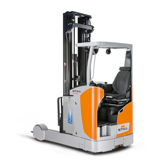
Overviews Overview Overview Overhead guard Battery Driver's compartment Side support (tilt protection) Lift mast Control compartment Fork arms Drive wheel Load wheel Step Battery frame 50988078001 EN - 11/2021 - 10... -
Page 69: Overview Of The Driver's Compartment
Overviews Overview of the driver's compartment NOTE The truck equipment may differ from the equipment shown. Overview of the driver's compartment 2 3 4 Steering wheel Cup holder for max. 1.5-l bottles Button for speed limitation, creep speed Operating devices for hydraulic and traction (variant) functions Electrical seat adjustment push button (var-... -
Page 70: Shelves And Cup Holders
Overviews Shelves and cup holders NOTE The truck equipment may differ from the equipment shown. Shelves and cup holders WARNING Objects may fall into the footwell and obstruct the pedals, which poses a risk of accident! Objects to be stored must be of the correct size so that they do not fall from the shelves (1, 4) or out of the cup holder (2). -
Page 71: Operating Devices And Display Elements
Overviews Operating devices and display elements Operating devices and display elements Display and operating unit Display of the operating statuses Drive programme button (P1-P4) Keypad for lift height preselection (variant) Blue-Q button or PIN code access (variant) Parking brake button Keypad for onboard diagnostics, parameter- ising 50988078001 EN - 11/2021 - 10... -
Page 72: Operating Status Displays On The Display And Operating Unit
20% of the nominal capacity, only the last seg- Battery charging state ment will still flash. A hydraulic limitation and/or driving limitation can be implemen- ted as an option. The hydraulic limitation and/or driving limitation must be activated by the authorised service centre. -
Page 73: Display Messages
Overviews Operating devices and display elements Item no. Display Comment Relevant only for the "lift height preselec- Function assistant tor" variant Function assistant, centre position for tran- sition shift Function assistant, centre position for tilt- Operating hours, error messages, drive The meter displays up to 99,999.9 operat- profile, information text ing hours. - Page 74 Remove obstacles. tor. Then fully lower the fork to ref- erence the system. ● If the message is still dis- played after cleaning, contact your authorised service centre. ● Emergency off switch of the Switch off the truck. Unlock the...
- Page 75 ● Lithium-ion battery is in ● Switch off the truck emergency operation ● If the message is still dis- ● Driving speed and hydraulic played after restarting, contact speed may be restricted your authorised service centre ●...
- Page 76 ● Restart the truck S5951 ● All truck functions are disa- ● If the message is still dis- bled played after restarting, contact your authorised service centre ● Switch off the truck ● Overtemperature of the lithi- ●...
-
Page 77: Entering Truck Operating Data Via The Display And Operating Unit
Overviews Operating devices and display elements Entering truck operating data via the display and operating unit Authorisation levels The authorisation levels determine which op- erating data and functions the user can ac- cess. The higher the authorisation level, the more comprehensive the access to truck oper- ating data. - Page 78 Overviews Operating devices and display elements Level 3 (authorised service centre) Access: Press OK and ESC for 4 seconds and enter the password for level 3 Authorisations: Maintenance interval PIN for remote data transfer via SIM card Delete error list Accessing the main menu without a password (authorisation level 1) First of all, press the OK button to open the...
- Page 79 Overviews Operating devices and display elements PASSWORD NOT VALID The message appears for three seconds and then the display and operating unit shows the input screen for the password again. The password can be entered again. If the password is entered incorrectly a third time, the input screen is locked for five mi- nutes.
- Page 80 Overviews Operating devices and display elements Overview of the menu structure Authori- sation Main menu Submenu (level) Edit/select Comment CONFIGU- RATION Language se- List of available lection for the LANGUAGE languages display and op- erating unit TIME HH : MM DATE YY : MM : DD LEAD...
-
Page 81: Lithium-Ion Battery Display
Overviews Operating devices and display elements Authori- sation Main menu Submenu (level) Edit/select Comment CONFIGU- RATION SERVICE IN XXX h ERROR RE- A–Z, *: all devi- Lithium-ion battery display The lithium-ion battery has its own display. The display shows information about the error status (1), the temperature (2) and the charg- ing status (3) of the lithium-ion battery. -
Page 82: Joystick 4Plus
Overviews Operating devices and display elements Joystick 4Plus "Transition shift" slider Reserve Shift button "F" (auxiliary hydraulics control- Pictograms for operation of the 5th and 6th ler) hydraulic function (variant) Drive direction switch Pictograms for operation of the basic hy- Joystick, "lifting/lowering"... -
Page 83: Fingertip
Overviews Operating devices and display elements Fingertip "Lift/lower" operating lever "Transition shift/tilt centre position" push but- "Shift" operating lever ton (variant) "Tilt" operating lever Reserve "Transition shift" operating lever "Auxiliary hydraulics" push button (variant) Emergency off switch Drive direction switch "Enable"... - Page 84 Overviews Operating devices and display elements 50988078001 EN - 11/2021 - 10...
-
Page 85: Operating
Operating... -
Page 86: Checks And Tasks Before Daily Use
Operating Checks and tasks before daily use Checks and tasks before daily use Visual inspections and function checking DANGER Risk of explosion if hydrogen builds up in the cab! If the truck is equipped with a cab, hy- drogen from the battery compartment can ingress into the cab through un- sealed bores. - Page 87 Operating Checks and tasks before daily use CAUTION Risk of component damage! A deformed or damaged battery male connector can cause overheating and related consequential dam- age. – Check the battery male connector for damage. – If necessary, have the battery male connector re- placed by the authorised service centre.
- Page 88 Operating Checks and tasks before daily use Component Course of action Perform a visual inspection for wear and damage. Make sure that only approved tyre types are used (see the chapter entitled " Technical data/Wheels and tyres"). Wheels, tyres In the event of uneven tyre wear on the load wheels, change both tyres.
-
Page 89: Climbing Into And Out Of The Truck
Component Course of action Perform a visual inspection for integrity. Ensure cleanliness. Make sure that the antistatic belt is still long enough Antistatic belt, corona electrode to touch the ground. The discharge wires of the corona electrode must not touch the ground. The wires discharge the ener- gy to the air. - Page 90 Operating Checks and tasks before daily use WARNING Risk of injury when jumping out of the truck! If the driver jumps out the truck while it is moving, he or she could fall under the truck or be crushed by an obstacle.
-
Page 91: Adjusting The Msg 65/Msg 75 Driver's Seat
Operating Checks and tasks before daily use Adjusting the MSG 65/MSG 75 driver's seat WARNING Risk of accident from sudden adjustment of the seat or of the seat backrest! If the seat or the seat backrest is adjusted uninten- tionally, it can lead to uncontrolled movements by the driver. - Page 92 Operating Checks and tasks before daily use Moving the driver's seat – Lift the lever (1) and hold. – Push the driver's seat into the desired posi- tion. – Release the lever. – Ensure that the driver's seat is securely en- gaged.
- Page 93 Operating Checks and tasks before daily use Adjusting the seat suspension NOTE The MSG 75 seat is equipped with electric air suspension that is activated using an electric switch instead of a lever (3). The driver's seat can be adjusted to suit the weight of the individual driver.
- Page 94 Operating Checks and tasks before daily use Adjusting the backrest extension (var- iant) – Adjust the backrest extension (6) by pulling it out or pushing it into the desired position. To remove the backrest extension, move it past the end stop by jolting it upwards. Switching the seat heater (variant) on ...
-
Page 95: Adjusting The Steering Column
Operating Checks and tasks before daily use Adjusting the horizontal suspension (variant) – Push the lever (8) in sideways and slide the driver's seat to the locked position. To re- lease, push the lever outwards. Using the lever (9), the driver can adjust the hardness in several levels. -
Page 96: Filling The Washer System (Variant)
Operating Checks and tasks before daily use Filling the washer system (var- iant) The washer reservoir is located behind the driver's seat in the weather protection cab. The filling opening is accessible from above. – Open the washer system filler cap (1). –... -
Page 97: Unlocking The Emergency Off Switch
Operating Checks and tasks before daily use Unlocking the emergency off switch Unlocking the emergency off switch – Pull the emergency off switch (1) upwards until it is unlocked. Access authorisation with PIN code (variant) The truck functions can be activated using a five-digit PIN code. -
Page 98: Operating The Signal Horn
Operating Checks and tasks before daily use Operating the signal horn NOTE The signal horn is used to warn people against imminent danger or to announce your intention to overtake. – Push the signal horn button (1). The signal horn sounds. Checking the brake system for correct function DANGER... - Page 99 Operating Checks and tasks before daily use Checking the reverse brake – Accelerate the truck without a load in a clear area; see "Driving" chapter. – Change the drive direction in inching mode; see the chapter entitled "Selecting the drive direction".
-
Page 100: Checking The Steering System For Correct Function
Operating Checks and tasks before daily use Checking the steering system for correct function – Operate the steering wheel (1). The steer- ing must be continuous and move freely. NOTE In the "180° steering" variant, the drive's maxi- mum steering angle is ±90°. 5060_003-031 Checking the emergency off ... -
Page 101: Checking The "Automatic Tilting Centre Position" (Variant) For Correct Function
Operating Checks and tasks before daily use Checking the "automatic tilting centre position" (variant) for cor- rect function NOTE Perform the "Automatic tilt to centre position" function check each time before using the truck. The driver can use the "automatic tilt to centre position"... -
Page 102: Switching On
Operating Switching on Switching on Switching on the key switch WARNING Before switching on the key switch, all tests prior to commissioning must be performed without any de- fects being detected. – Carry out checks prior to commissioning (refer to the chapter entitled "Checks and tasks to be car- ried out prior to commissioning"). - Page 103 Operating Switching on Displays after the switch-on process (for trucks with default options) NOTE Depending on the truck equipment, further in- formation may be visible on the display and operating unit. Battery charge(1) The usable battery charge is shown in the dis- play field.
- Page 104 Operating Switching on direction is only selected when the drive direc- tion switch has been actuated once. Operating hours(3) The current value of the hour meter is shown in the display field. Drive programme(4) The current drive programme (1-4) is shown in the display field.
-
Page 105: Lighting
Danger of damage to eyes from looking into the STILL SafetyLight. Do not look into the STILL SafetyLight. The STILL SafetyLight is a warning unit to en- able early detection of trucks in driving areas with low visibility (such as drive lanes, high racks and at blind junctions). -
Page 106: Switching The Working Spotlights (Variant) On And Off
Operating Lighting Switching the working spotlights (variant) on and off There is an option to have the truck fitted with one or several working spotlights (1) to im- prove illumination of the working area. – Switch on the truck. –... -
Page 107: Daytime Running Lights / Footwell Lighting (Variant)
Operating Lighting Daytime running lights / footwell lighting (variant) The daytime running lights (1) increase the visibility of the truck. They make the truck more visible in the surroundings and for driv- ers of approaching trucks. The footwell lighting (2) increases safety for the driver, especially when climbing in and out of the truck frequently in poorly lit rooms. -
Page 108: Efficiency And Drive Modes
Operating Efficiency and drive modes Efficiency and drive modes Blue-Q efficiency mode The Blue-Q efficiency mode affects both the drive unit and the activation of the additional consumers and reduces the truck's energy consumption. If the efficiency mode has been activated, the acceleration behaviour of the truck changes to make acceleration more moderate. - Page 109 DANGER The stability limits defined by the laws of physics are still in effect even when the "reduction of speed when turning" function is active. There is a risk of tipping! – Before using this function, familiarise yourself with the change to the truck's driving and steering characteristics.
- Page 110 Operating Efficiency and drive modes DANGER Risk of tipping due to change in vibration character- istics of the load! If the controller is switched off or fails, the speed of the hydraulic functions will no longer be reduced. – Always adapt the use of the hydraulic functions to suit the situation.
-
Page 111: Driving
Operating Driving Driving Safety regulations when driving Driving conduct The driver must comply with the highway code when driving within the plant. The speed must be appropriate to the local conditions. For example, the driver must drive slowly around corners, in and around tight passage- ways, when driving through swing doors, at blind spots or on uneven roadways. - Page 112 There is a risk of acci- dent! – Do not use devices during travel or when handling loads. – Set the volume so that warning signals can still be heard. WARNING In areas where the use of mobile phones is prohibi- ted, it is absolutely not permitted to use a mobile phone or radio telephone.
-
Page 113: Roadways
Operating Driving Any glass and mirrors must always be clean and free of ice. Panoramic mirror The panoramic mirror (1) may only be used for observing the road area on the load side of the truck and not for travelling in the load di- rection. - Page 114 Operating Driving The truck is designed for normal operation on smooth, even roadways without major gradi- ents, up to a maximum of 3%. The following gradients (e.g. on ramps) must not be exceeded when using the truck under any circumstances: Max.
-
Page 115: Side Chassis Supports
Operating Driving based on the overall height of the truck's lift mast and the dimensions of the load. Rules for roadways and the working area It is only permitted to drive on routes author- ised for traffic by the operating company (see chapter "Responsible persons") or its repre- sentatives. -
Page 116: Enabling Truck Functions Using The Foot Switch And Seat Switch
Operating Driving Enabling truck functions using the foot switch and seat switch The foot switch and seat switch are there for safety purposes during operation of the truck. The complete range of truck functions is avail- able only when the driver is sitting on the driv- er's seat and then actuates the foot switch. - Page 117 Operating Driving The drive function is only enabled if: The parking brake has been released ● The seat switch has been actuated but the ● accelerator pedals have not One of the accelerator pedals is then actu- ● ated The switches are all functioning correctly ●...
-
Page 118: Setting The Drive Programme
Operating Driving Setting the drive programme Setting The driving and braking characteristics of the drive can be set on the display and operating unit. Four different drive programmes can be set. Depending on the drive programme selected, different driving characteristics are applied in relation to the maximum speed, acceleration behaviour* and deceleration behaviour**. -
Page 119: Selecting The Drive Direction
Operating Driving Selecting the drive direction The desired drive direction of the truck must be selected using the drive direction switch before attempting to drive. When the truck is switched on, there is initially no drive direction selected. The drive direction indicator on the display and operating unit shows the "neutral position"... -
Page 120: Actuating The Drive Direction Switch, Joystick 4Plus
Operating Driving NOTE When the driver leaves the seat, the direction switch is set to neutral. To drive, the direction switch must be actuated again. Actuating the drive direction switch, joystick 4Plus – For "travelling in the load direction", press the drive direction switch (1)up. -
Page 121: Starting Drive Mode, Single-Pedal Version
Operating Driving Starting drive mode, single-ped- al version DANGER Being trapped under a rolling or tipping truck could cause fatal injuries. – Sit down on the driver's seat. – During work, ensure that you have a secure grip on the truck and a stable seat position. Hold on tight to the steering wheel with your left hand. - Page 122 The truck cannot be driven again until the accelerator pedal has been released and then actuated again. If the truck still cannot be operated, park it securely and contact your authorised service centre. 50988078001 EN - 11/2021 - 10...
-
Page 123: Starting Drive Mode, Dual-Pedal Version (Variant)
Operating Driving Starting drive mode, dual-pedal version (variant) DANGER Being trapped under a rolling or tipping truck could cause fatal injuries. – Sit down on the driver's seat. – During work, ensure that you have a secure grip on the truck and a stable seat position. Hold on tight to the steering wheel with your left hand. - Page 124 If the truck still cannot be op- erated, park it securely and contact your au- thorised service centre.
-
Page 125: Operating The Service Brake
Operating Driving Operating the service brake Electrical braking recovers energy for the bat- tery. This results in a longer operating time be- tween the charging processes and less wear to the brakes. The electric brake converts the acceleration energy of the truck into electrical energy as soon as the accelerator pedal is released. -
Page 126: Applying The Electromagnetic Parking Brake
Operating Driving Applying the electromagnetic parking brake DANGER There is a risk of fatal injury from being run over if the truck rolls away. – Only leave the truck once the parking brake has been applied. – The truck must not be parked on a slope. –... - Page 127 Operating Driving – Sit on the driver's seat. – Select the drive direction (single-pedal ver- sion only). – Press the foot switch. – Actuate the accelerator pedal. The parking brake is released automatically and audibly, and the symbol on the display and operating unit disappears.
-
Page 128: Steering
Operating Driving The symbol (2) is shown in the display and op- erating unit. Automatic application of the parking brake Cause Effect The parking brake is applied immediately and audibly. The symbol (2) is shown briefly on the If the truck is switched off: display and operating unit until the control units switch off. - Page 129 Operating Driving 180° steering (variant) The steering wheel has no mechanical stops and can be continuously turned. The path of travel (1) is determined by turning the steering wheel. The maximum steering an- gle of the steered wheel is 90° to each side. To reverse the drive direction, the drive direc- tion switch must be actuated.
-
Page 130: Switching Between 360°/180° Steering (Variant)
Operating Driving Switching between 360°/180° steering (variant) On trucks with "360 – 180° switchable steer- ing" (variant), the driver can set their preferred steering setting. The driver can see the cur- rent steering setting from the pictogram on the additional rocker switch. When the truck is at a standstill, the driver can switch directly between 360°... - Page 131 Operating Driving speed. The error message disappears. The driving speed restriction ends. Switching the steering setting Before attempting to drive the truck, the driver must check the position of the rocker switch for switching the steering setting. The selected steering setting must match the steering com- 360°...
-
Page 132: Emergency Operation Of The Reach Measurement System
Operating Driving Emergency operation of the reach measurement system When driving over bumps or foreign bodies in the reach measurement system, the system can temporarily lose the current shift position. If the reach travel position cannot be meas- ured, the measurement system operates only in emergency operation. - Page 133 Operating Driving Checking the reach measurement sys- tem for foreign objects DANGER Risk of injury due to movement of the reach car- riage during the test Switch the truck off before the test. Disconnect the battery male connector. The reach measurement system consists of the reach travel sensor (1) and a reference bar (2).
-
Page 134: Parking
Operating Parking Parking Parking the truck securely DANGER There is a risk of fatal injury from being run over if the truck rolls away. – The truck must not be parked on a slope. – In emergencies, secure with wedges on the side facing downhill. - Page 135 Operating Parking – Lower the fork to the ground. – Tilt the lift mast forwards until the tips of the fork arms rest on the ground. – If attachments (variant) are fitted, retract the working cylinders. – Switch off the truck. If the switch key is present, pull it out (variant).
-
Page 136: Lifting
Operating Lifting Lifting Lifting system variants The movement of the fork carriage and the lift mast heavily depends on the following equip- ment: The lift mast fitted on the truck; see the ● chapter entitled "Lift mast versions" The operating device that is used to control ●... -
Page 137: Lifting System Operating Devices
Operating Lifting Triplex lift mast (variant) During lifting, the inner lift cylinder raises the fork carriage up to the free lift (2) and then the outer lift cylinders raise the inner lift mast straight up to the max. height (3). Lifting system operating devices The method of operating the lifting system de- pends on the operating devices included in the... -
Page 138: Joystick 4Plus Lifting System
Operating Lifting Joystick 4Plus lifting system A / B Lowering/lifting the fork carriage E / F Transition shift (variant) C / D Tilting the lift mast (variant) G / H Shifting DANGER Reaching or climbing between moving parts of the truck (e.g. - Page 139 Operating Lifting In this version, the hydraulic functions are con- trolled using the joystick 4Plus. The pictogram (1) shows the basic hydraulics functions and how they are controlled using the joystick. The pictogram (2) shows the 3rd and 4th functions and their operation.
- Page 140 Operating Lifting Tilting the lift mast or fork carriage (var- iant) Depending on the truck equipment, either the entire lift mast is tilted or just the fork carriage (fork tilter). To tilt the lift mast backwards: – Push the rocker button (2) towards" ".
-
Page 141: Fingertip Lifting System
Operating Lifting Shifting To extend the reach carriage: – Push the joystick (4) towards " ". To retract the reach carriage: – Push the joystick (4) towards " ". NOTE The pictograms on the base of the joystick show the direction of movement for the corre- sponding hydraulic function. - Page 142 Operating Lifting DANGER Reaching or climbing between moving parts of the truck (e.g. lift mast, sideshifts, working equipment, load carrying devices etc.) can lead to serious in- jury or death and is therefore prohibited. – Always observe the safety regulations for handling loads;...
-
Page 143: Electronic Lowering Stop Function
Operating Lifting Transition shift to the left: – Push the "transition shift" operating lever (4) forwards. Transition shift to the right: – Pull the "transition shift" operating lever (4) backwards. NOTE The pictograms on the operating levers show the direction of movement for the correspond- ing hydraulic function. -
Page 144: Automatic Lift Cut Out (Variant)
Operating Lifting Automatic lift cut out (variant) The automatic lift cut-out interrupts the lifting of the load at a certain height. The height must be set by the authorised service centre. Intermediate lift cut-out (acknowledgea- ble) The intermediate lift cut-out makes frequent approaches to a required lift height easier. -
Page 145: Reach-Lower Lock (Variant)
Operating Lifting Reach-lower lock (variant) The reach/lower lock prevents the load forks from being lowered between the running wheel beams for the entire time that the reach carriage is in the retracted position. As a re- sult, wide loads cannot accidentally come to rest on the running wheel beams during lower- ing and become unstable. -
Page 146: Automatic Centre Position (Variant)
Operating Lifting Automatic centre position (var- iant) Automatic transition shift centre position The driver can use the "automatic transition shift centre position" function to position the transition shift in the centre automatically. To do this, the pushbutton must be actuated until the function switches off automatically. -
Page 147: Fork Wear Protection (Variant)
Operating Lifting Automatic tilting centre position The driver can use the "automatic tilt to centre position" function to change the tilt of the fork arms to 0° automatically. To do this, the push- button must be actuated until the function switches off automatically. - Page 148 Operating Lifting The fork arms are protected against wear and the building floor is protected against damage. There are two versions, depending on the height measuring system of the truck. Electronic fork wear protection (variant) NOTE This variant is only available for vehicles with the optical height measuring system (variant).
-
Page 149: Speed Limitation Safety Function
Operating Lifting Speed limitation safety function WARNING There is always an increased risk of the truck tipping if it is driven with a raised load. The system is a support for the driver when placing items into stock and removing items from stock. The responsibility for safe operation and complying with safety regulations remains with the driver. - Page 150 Operating Lifting NOTE For installation and removal, a transport ● pallet is recommended for supporting the fork arms. The pallet size depends on the fork arm size used and should be dimen- sioned such that the fork arms do not pro- trude after being placed on the pallet.
-
Page 151: Fork Extension (Variant)
Operating Lifting DANGER There is a risk to life caused by a falling load or fork! – Tighten the locking screw after every fork replace- ment. – It is not permitted to drive or transport loads with- out the locking screw. Fork extension (variant) DANGER There is a risk of being run over if the truck rolls... - Page 152 Operating Lifting Attachment DANGER Risk to life from falling load! At least 60% of the length of the fork extension must lie on the fork arm. A maximum 40% overhang over the fork arm end is permissible. The fork extension must also be secured against slipping from the fork arm.
-
Page 153: Load Backrest (Variant)
Operating Lifting Load backrest (variant) The load backrest (1) prevents individual packages from falling backwards when stack- ing high loads. Working platforms The use of working platforms in conjunction with industrial trucks is regulated by national law. This legislation should be observed. The use of working platforms is only permitted by virtue of the legislation in the country of use. - Page 154 Operating Lifting An incorrect extension sequence can be caused by the following: The hydraulic oil temperature is too low ● The fork carriage is blocked in the inner lift ● mast The free lift cylinder is blocked ● The chain roller for the free lift cylinder is ●...
-
Page 155: Handling Loads
Operating Handling loads Handling loads Safety regulations when handing loads The safety regulations for handling loads are shown in the following sections. DANGER There is a risk to life caused by falling loads or if parts of the truck are being lowered. –... - Page 156 Operating Handling loads WARNING The figures show examples. Only the capacity rating plates on the truck are valid! The attachment of additional weights to in- crease load capacity is prohibited. DANGER Risk to life from the truck losing stability! Never exceed the maximum loads shown! These val- ues apply to compact and homogeneous loads.
-
Page 157: Picking Up Loads
Operating Handling loads Example Weight of load to be lifted (1) Permissible lift height (2) Load distance from fork back (3) WARNING Risk of accident from the truck losing stability! The permissible loading of the attachments (variant) and the reduced load capacity of the combination of truck and attachment must not be exceeded. - Page 158 Operating Handling loads If possible, the load should rest on the back of the fork. The load must not protrude too far over the fork tips, nor should the fork tips protrude too far out from the load. Loads must be picked up and transported as close to the middle as possible.
-
Page 159: Danger Area
Operating Handling loads Adjusting the fork – Lift the locking lever (1) and move the fork arms to the desired position. – Allow the locking lever to snap back into place. The load centre of gravity must be midway be- tween the fork arms. -
Page 160: Transporting Pallets
Operating Handling loads DANGER Danger of death from falling loads! – Never walk or stand underneath sus- pended loads. Transporting pallets As a rule, loads (e.g. pallets) must be trans- ported individually. Transporting multiple loads at the same time is only permitted: when instructed by the supervisor and ●... -
Page 161: Picking Up A Load
Operating Handling loads DANGER Loss of stability! Slipping or swinging suspended loads can lead to a loss of stability and cause the truck to tip over. – When transporting suspended loads, observe the following instructions. Instructions for transporting suspended loads: Swinging of the load is to be prevented by ●... - Page 162 Operating Handling loads DANGER There is a risk to life caused by a falling load or if parts of the truck are being lowered. – Never walk or stand underneath suspended loads or raised fork arms. – Never exceed the maximum load indicated on the capacity rating plate.
- Page 163 Operating Handling loads – Extend the reach carriage until the fork back is resting on the load. The load centre of gravity must be midway be- tween the fork arms. – Slowly raise the fork carriage until the load is lifted clear of the racking.
- Page 164 Operating Handling loads – Ensure that the roadway on the drive side is clear. Move backwards carefully and slowly until the load is clear of the racking. – Brake. – Lower the load carefully while maintaining ground clearance. Lower wider loads that do not fit between the load wheel posts only until they are not resting on the posts.
-
Page 165: Transporting Loads
Operating Handling loads – Tilt the fork tips or lift mast fully to the drive side into the driving position. – Release the brake. The load can be transported; see the chapter entitled "Transporting loads". Transporting loads NOTE Observe the information in the chapter entitled "Safety regulations when driving". - Page 166 Operating Handling loads When travelling, the reach carriage must be fully retracted and the fork carriage lowered until just above the load wheel legs. If possible, always travel on roadways in the drive direction, as the load side view is restric- ted by the lift mast and the load.
-
Page 167: Setting Down Loads
Operating Handling loads – Never drive with a load protruding on one side or with a load shifted to the side (side- shift). The centre of gravity of the load must always be positioned on the longitudinal ax- is of the truck. Setting down loads ... - Page 168 Operating Handling loads – Tilt the fork arms or lift mast until the fork arms are horizontal. – Raise the load to just above the required height. – If necessary operate the sideshift to position the load centrally. – Extend the reach carriage fully. –...
-
Page 169: Driving On Upward And Downward Gradients
Operating Handling loads Driving on upward and down- ward gradients DANGER Danger to life! On upward and downward gradients, the load must be carried facing uphill. It is only permitted to drive on upward and downward gradients if they are marked as traffic routes and can be used safely. - Page 170 Operating Handling loads Determining the total actual weight – Park the truck securely. – Determine the unit weights by reading the truck nameplate and, if necessary, the at- tachment (variant) nameplate and, if neces- Type-Modèle-Typ / Serial no.-No. de série-Serien-Nr. / year-année-Baujahr sary, by weighing the load to be lifted.
-
Page 171: Attachments
Fitting attachments If the truck is equipped with an integrated at- tachment (variant) at the factory, the specifica- tions in the STILL operating instructions for in- tegrated attachments must be observed. If attachments are fitted at the place of use,... - Page 172 Operating Attachments WARNING Risk of accident due to incorrect labelling! The use of attachments can cause accidents if the labelling is incorrect or missing. If the truck is not fitted with an attachment-specific residual load capacity rating plate, and the operating devices are not marked with the relevant pictograms, the truck must not be used.
- Page 173 Operating Attachments Plug connectors on the lift mast – Before fitting the attachment, depressurise the hydraulic system; see the chapter enti- tled "Depressurising the hydraulic system". CAUTION Risk of damage to components! Open connections on the plug connectors (1) can be- come dirty.
-
Page 174: Releasing The Pressure From The Auxiliary Hydraulics
Operating Attachments Releasing the pressure from the auxiliary hydraulics Attachments must only be fitted by competent persons in accordance with the information provided by the manufacturer and supplier of the attachments. After each installation, the at- tachment must be checked for correct function prior to initial commissioning. -
Page 175: General Instructions For Controlling Attachments
Operating Attachments DANGER When activating the valves for the purpose of de- pressurising the hydraulic lines, unexpected hy- draulic movements may occur. The "release the pressure from the hydraulics" truck function can be used to depressurise the entire hy- draulic system. For example, this means that the fork may lower faster than expected when the "lowering"... - Page 176 Operating Attachments WARNING Use of attachments can give rise to additional haz- ards such as a change in the centre of gravity, addi- tional danger areas etc. Attachments must only be used for their intended purpose as described in the relevant operating in- structions.
-
Page 177: Controlling Attachments (Variant) Using The Joystick 4Plus (5Th/6Th Hydraulic Function)
Operating Attachments Controlling attachments (variant) using the joystick 4Plus (5th/6th hydraulic function) The designation "5th/6th function" refers to the fact that the four operating levers control four functions, while additional functions can be controlled by switching functions. In this version, the attachments are controlled using a joystick. - Page 178 Operating Attachments Overview of pictograms and operating devices No. Operating device Function of the attachment Joystick + shift but- Fork prong positioner: close/open ton "F" Vertical rocker but- Fork positioner: forwards/backwards ton + shift button "F" Vertical rocker but- Rotator: left/right ton + shift button "F"...
-
Page 179: Controlling Attachments (Variant) With The Fingertip (5Th/6Th Hydraulic Function)
Operating Attachments pictogram indicates the combination of operat- ing devices required for the particular attach- ment. Controlling attachments (variant) with the fingertip (5th/6th hy- draulic function) The designation "5th/6th function" refers to the fact that the four operating levers control four functions, while additional functions can be controlled by switching functions. - Page 180 Operating Attachments NOTE The pictograms for the operating levers are at- tached according to the attachments fitted to this truck at the factory. If an attachment with other functions is fitted, the pictograms must be checked for the correct representation and changed if necessary.
-
Page 181: Operating The Clamp Locking Mechanism (Variant) With A Joystick 4Plus
Operating Attachments Operating the clamp locking mechanism (variant) with a joy- stick 4Plus This truck can be fitted with a clamp locking mechanism as a variant. This prevents the clamp from opening unintentionally if the oper- ating function is inadvertently triggered. DANGER There is a risk of fatal injury from falling loads if the correct function of the clamp locking mechanism is... - Page 182 Operating Attachments – Keep shift button "F" depressed and move the horizontal rocker button back into the neutral position. The LED (4) indicating the clamp locking mechanism has been unlocked lights up and the clamp can now be opened. If the clamp locking mechanism is locked again, the LED will go out.
-
Page 183: Operating The Clamp Locking Mechanism (Variant) With The Fingertip Switch
Operating Attachments Operating the clamp locking mechanism (variant) with the fin- gertip switch This truck can be fitted with a clamp locking mechanism as a variant. This prevents the clamp from opening unintentionally if the oper- ating function is inadvertently triggered. DANGER There is a risk of fatal injury from falling loads if the correct function of the clamp locking mechanism is... -
Page 184: Picking Up A Load Using Attachments
Operating Attachments – Keep shift button "F" depressed and move the operating lever back into the neutral position. The LED (4) indicating the clamp locking mechanism has been unlocked lights up and the clamp can now be opened. If the clamp locking mechanism is locked again, the LED will go out. - Page 185 Operating Attachments Load capacity Q (kg) (1) ● Lift height h (mm) (2) ● Load distance C (mm) (3) ● 50988078001 EN - 11/2021 - 10...
-
Page 186: Assistance Systems
Operating Assistance systems Assistance systems Automatic fork centre position during lowering (variant) Function of the assistance system The assistance system assists the driver in lowering the load between the load wheel sup- ports. When lowering in free lift, the transition shift with the fork carriage automatically moves to the centre position. - Page 187 Operating Assistance systems CAUTION The driver must use the assistance system only when the truck is at a standstill. – Always stop the truck before using the "Semi-au- tomated approach to the fork centre position" as- sistance system. Operating the assistance system The assistance system is active when lower- ing in free lift.
-
Page 188: Lowering Protection Assistant (Variant)
Operating Assistance systems Stopping the assistance function during lowering The assistance function stops ● If the joystick or fingertip switch is operated below the activation threshold ● If the transition shift is operated manually with the joystick or fingertip switch ●... - Page 189 Operating Assistance systems driver remains responsible for lowering the forks safely. Operating the assistance system A sensor on the lift mast detects that the fork is resting on the rack. The truck issues mes- sage on the display-operating unit and emits a signal tone.
-
Page 190: Auxiliary Equipment
Operating Auxiliary equipment Auxiliary equipment FleetManager (variant) FleetManager is an equipment variant and can be fitted to the truck in different versions. The description and operating information can be found in the separate operating instructions for the corresponding FleetManager versions. FleetManager regulates the access authorisa- tion for the truck. - Page 191 Even if vibration damping of the lift mast is inactive, the driver can still operate all of the truck's hydraulic functions. – If active vibration damping fails, take the change in vibration characteristics into consideration.
-
Page 192: Optical Height Measuring System (Variant)
Operating Auxiliary equipment Optical height measuring system (variant) This truck is equipped with an optical height measuring system. The system is immediately available after the truck is switched on. The components are located to the side on the lift mast. The system consists of a compact LED/sensor unit on the lift mast frame and a reflector on the fork carriage. - Page 193 Contamination will affect the ● Clean the sensor glass and measuring signal between the reflector. LED height sensor and reflec- ● If the message is still dis- tor. played after cleaning, contact your authorised service centre. CAUTION Incorrect cleaning can damage the sensor glass and the reflector.
- Page 194 If the mal- function in the system still exists, please con- tact the authorised service centre. In the event of a malfunction, an error number is shown in the display.
- Page 195 Operating Auxiliary equipment Possible cause Truck response Rectifying the error Error number A3140 Incorrect measurements Lifting functions can only be ● Check the light signal path caused by a reflective object in operated in emergency opera- between the sensor and the re- the light signal path between tion.
-
Page 196: Load Measurement (Variant)
Operating Auxiliary equipment Reach/lower lock ● Active load stabilisation (ALS) ● OPTISPEED ● Fork wear protection ● Mast transfer damping ● In emergency operation, functions that are de- pendent on the lift height operate with calcula- ted lift heights rather than measured lift heights due to the missing measured value. - Page 197 Operating Auxiliary equipment General The "load measurement" variant helps the driver by displaying the weight of the lifted load on the display and operating unit. The weight is measured by an additional weight sensor at the valve block. The sensor measures the weight with a deviation of +/-10% of the nominal load of the truck.
-
Page 198: Speed Limitation Based On Lift Height
Operating Auxiliary equipment NOTE The displayed value of the load measurement is invalid if the fork carriage is positioned ex- actly between the free lift height and main lift height during the measurement. In this case, the measurement must be repeated at a differ- ent position. -
Page 199: Button For Speed Limitation, Creep Speed (Variant)
Operating Auxiliary equipment set maximum speed. If the current driving speed is already above this maximum speed, the truck brakes regeneratively to the set max- imum speed. The speed limitation is removed as soon as the current lift height is lowered to below the specified value. -
Page 200: Camera/Monitor System (Variant)
The pedal plate and seat console move during ad- justment. – Change settings only when the truck is at a stand- still. – Keep your fingers away from moving parts during adjustment of the driver's compartment. For safety reasons, place your right hand on the joystick. Ac- tuate the rocker switch with your left hand. -
Page 201: Overhead Guard With Optimised Visibility (Variant)
Operating Auxiliary equipment CAUTION Risk of component damage. Adjustment of the driver's compartment must only be carried out in the seated position by persons weigh- ing a maximum of 150 kg. – Observe the total permissible weight during ad- justment of the driver's compartment. NOTE Before operating the seat-adjustment mecha- nism, make sure that there is sufficient clear-... -
Page 202: Clipboard (Variant)
Operating Auxiliary equipment DANGER Risk of fatal injury in the event of a damaged roof panel. In the event of any damage to the roof panel, particu- larly cracks, the truck must be switched off immedi- ately. The roof panel must then be replaced (safety- relevant component). -
Page 203: Battery Change Frame (Variant)
Operating Battery change frame (variant) Battery change frame (variant) General The battery rack is equipped with two adjacent roller channels. The battery is pulled out of the truck by hand on to the battery rack and is pushed by hand off the battery rack into the battery compart- ment of the truck. -
Page 204: Area Of Application
Operating Battery change frame (variant) number of the intended battery are to be taken from the order documentation. The maximum load capacity of the battery rack and its net weight are to be taken from the nameplate. WARNING Danger of overloading For mobile use, it must be ensured that the load bearing capacity of the truck to be used for transpor- tation is sufficient for the weight of the battery and... -
Page 205: Locking The Battery Change Frame
Operating Battery change frame (variant) Locking the battery change frame DANGER Risk of physical injury Before unlocking the swing bolt, check that the bat- tery rack is on a horizontal surface and that the floor has a sufficient load capacity. This is the only way to ensure that the battery does not move in an uncon- trolled manner and trap or crush parts of the opera- tor's body. - Page 206 Operating Battery change frame (variant) Requirements for positioning the change frames The transfer height of the frame and truck must be aligned with one another; see the chapter entitled "Battery change frame/Adjust- ing the transfer height" In order to move the battery in and out easily, the roller channels must be set exactly hori- zontal.
-
Page 207: Lift Height Preselector / Easy Target (Variant)
Operating Lift height preselector / easy Target (variant) Lift height preselector / easy Target (variant) General The lift height preselector supports the user when placing loads into stock/removing loads from stock. There are 160 programmable lev- els grouped into eight areas (A-H), each with 20 levels. -
Page 208: Definition Of Terms
Operating Lift height preselector / easy Target (variant) Definition of terms Level One target height can be assigned to each level. Valid levels can be reached semi-auto- matically. Area Level 1-20 A warehouse can be divided into eight areas Area A-H and each area can contain up to 20 levels. -
Page 209: Auto Mode Function
Operating Lift height preselector / easy Target (variant) If the load support is not in free lift, a reference drive is required. In this process, the load sup- port is lowered until it is below the reference switch, then raised again. Reference height The reference height is the distance from the upper edge of the load support to the floor... - Page 210 Operating Lift height preselector / easy Target (variant) If the reach carriage is not in the basic posi- ● tion, the assistant specifies "retract reach carriage" until the basic position is reached. If the basic position is reached, only lifting ●...
- Page 211 Operating Lift height preselector / easy Target (variant) AUTO MODE height preselection "With- out fork cycle" and "Start only with fork below target height" In the two modes "Basic position" and "Any position", an additional selection can be made between the options "Without fork cycle" and "Start only with fork below target height".
-
Page 212: Operating The Lift Height Preselector
NOTE If height preselection is active, only the arrow symbols for movements that are still possible will light up on the function symbols in the as- sistant (1). The required movement is identi- fied in each case by a corresponding flashing arrow symbol. - Page 213 Operating Lift height preselector / easy Target (variant) NOTE During free lift, the difference between the ref- erence height and the target height is shown on the display as the "lift height remaining until target (target difference)" (6). The display does not show the difference between the cur- rent lift height and target height until after the reference switch has been passed.
- Page 214 Operating Lift height preselector / easy Target (variant) – Activate the lift function (displayed by the assistant). The selected height plus the pal- let free lift height is reached and the auto- matic stop is performed (6). The display (5) shows a distance to the target ≤...
-
Page 215: Teach-In, General
Operating Lift height preselector / easy Target (variant) CAUTION If the removing from stock button (1) is not pressed, all hydraulic functions are available without restriction (= manual operation)! Pay attention to the symbols in the display! – Activate the lift function (displayed by the ... -
Page 216: Performing A Teach-In
Operating Lift height preselector / easy Target (variant) NOTE Before a new height can be set via the dis- play, a reference drive must be carried out. Heights that are below the reference height can be saved by entering them manually. However, if such a level is selected, automatic operation cannot be used. - Page 217 Operating Lift height preselector / easy Target (variant) Opening the lift height preselector menu – For information on the general operation of the truck configuration, as well as entering a password with a specific authorisation level, see the chapter entitled "Onboard truck configuration/General".
- Page 218 Operating Lift height preselector / easy Target (variant) Entering and saving lift heights for height preselection The programmable lift heights are entered us- ing the enter keys on the control panel. The result of each entry is displayed in the display field (1).
-
Page 219: Easy Target/Easy Target Plus (Variants)
Operating Lift height preselector / easy Target (variant) Programming the lift height (example: area A, level 07, lift height 5500 mm) Button Action Display A07 055 (X flashes) X Press, the flashing digit is re- --> the cursor advances one placed place A07 0550 (X flashes) X... - Page 220 Operating Lift height preselector / easy Target (variant) Trucks with easy Target easy are distinguished by the addi- Target Plus tional decal information on the operating de- vice. easy Target (variant) simplifies the approach to a easy Target required target height with the lift height prese- lector.
-
Page 221: Approaching Target Heights Using "Easy Target
Operating Lift height preselector / easy Target (variant) function. Once the selected target Target height has been reached, easy Target is activated by pressing the F button Plus again. For the entire time that the F button is pressed, the "Automatic tilt to centre position" function is executed. -
Page 222: Positioning The Fork Horizontally Using "Easy Target Plus
Operating Lift height preselector / easy Target (variant) Operation Result Display Switch on the lift height prese- The lift height preselector is The assistant for the lift height lector (push button A..H switched on. preselector (2) is displayed. the input field) The display (1) shows the tar- Lift or lower the fork using the The lifting or lowering proce-... - Page 223 Operating Lift height preselector / easy Target (variant) Operation Result Display Execute (before driving the fork into the racking): easy Target Plus Move the joystick or the finger- One of the two assistance ar- is acti- easy Target Plus tip console to the inactive posi- rows (6) is visible, indicating vated.
-
Page 224: Cab (Variant)
Operating Cab (variant) Cab (variant) General information about the Depending on the area of application, the truck can be equipped with a weather protec- tion cab or a cold store cab. Operating devices (variants) The operating devices for the hydraulic func- tions and driving are positioned and operated in the same way as those on the basic truck. - Page 225 Operating Cab (variant) Opening the cabin door from the out- side – Insert the key in the door lock (1), unlock and remove the key. – Pull the door handle (2) and release the door lock. – Open the cab door by pulling it outwards. NOTE There is no monitoring switch for the cab door.
-
Page 226: Closing The Cab Door
Operating Cab (variant) Closing the cab door DANGER Risk of fatal injury as a result of driving with the cab door open! The driver can be injured if he does not keep his en- tire body within the protective cab, or if he falls off the truck. -
Page 227: Cab Interior Lighting (Variant)
Operating Cab (variant) Operating device Function Heating system rocker Selection of two heating levels for the warm air heating sys- switch (door), 2-stage tem in the door Ventilation fan rocker Selection of two blower speeds switch, 2-stage Heating system rocker Selection of two heating levels for the warm air heating sys- switch (footwell), 2-stage tem under the steering wheel... -
Page 228: Heating System In The Cab (Variant)
Operating Cab (variant) Heating system in the cab (var- iant) Switching on the blower and heating system Rocker switch for heating system (door), 2- Rocker switch for heating system (head stage area), 2-stage Rocker switch for ventilation fan, 2-stage Rocker switch for heating system (footwell), 2-stage DANGER There is a risk of poisoning if heavily... - Page 229 Operating Cab (variant) DANGER The heating system overheats if the hot air cannot escape from it. There is a risk of fire! The heating system may only be switch- ed on if the blower is running and the heating system is not covered by objects (such as a jacket or cover).
-
Page 230: Emergency Exit Window In The Cab
Operating Cab (variant) Switching off the heating system and blower DANGER The heating system overheats if the hot air cannot escape from it. There is a risk of fire! The blower may only be turned off if the heating system is turned off. –... - Page 231 Operating Cab (variant) can no longer be opened. It is labelled EMER- GENCY EXIT ONLY. – Switch off the truck. – To make it easier to climb out, fold down the driver's seat backrest. – Pull both locking knobs (1) upwards until ...
-
Page 232: Cold Store Application
Operating Cold store application Cold store application General In order to make industrial trucks suitable for use in cold stores, the trucks must be fitted with auxiliary equipment and subjected to technical modifications. As a result of this change in setup, the operational behaviour, maintenance intervals and maintenance tasks differ to those for standard industrial trucks. -
Page 233: Description Of The Cold Store Equipment
Operating Cold store application Area of applica- Cold store equip- Temperature Operating time Comment tion ment range up to load is handled by storage and re- trieval trucks. Required -30°C Continuous Alternating be- tween indoor and outdoor use: time spent outdoors long enough for the condensation to drain off at... -
Page 234: Battery In The Cold Store
Operating Cold store application The cold store equipment for industrial trucks consists essentially of: Oil types suitable for the cold store, for use ● in the hydraulics and gearbox. Lubricants suitable for the cold store, for ● use on moving parts, such as gearing and chains. -
Page 235: Impermissible Use Of The Lithium-Ion Battery In The Shock Cold Store (-45°C)
Operating Cold store application Impermissible use of the lithium- ion battery in the shock cold store (-45°C) CAUTION Risk of component damage. The lithium-ion battery is not approved for use in shock cold stores (-45°C). – Do not drive into a shock cold store with the lithi- um-ion battery (even for a short period). - Page 236 Operating Cold store application NOTE In exceptional cases, the truck may also be driven into the cold store with a small amount of condensation. When doing so, prevent the condensation water on the truck from freezing. Water droplets on the sensor system and on the mechanical components must be removed by actuating the lift mast.
-
Page 237: Procedure In Emergencies
Operating Procedure in emergencies Procedure in emergencies Emergency shutdown CAUTION If the battery male connector (1) is disconnected or the emergency off switch (2) is actuated, the truck's electrical functions are switched off. This safety system must only be used in an emer- gency or to safely park the truck. -
Page 238: Procedure If Truck Tips Over
Operating Procedure in emergencies Switching off the truck in an emergency while it is moving In an emergency, all functions of the truck can be shut down. – Ensure that you have a secure grip on the truck; hold onto the steering wheel with your left hand. -
Page 239: Emergency Lowering
Operating Procedure in emergencies Emergency lowering DANGER Risk to life if the load drops too quickly! – Do not walk underneath the raised load! DANGER If the truck is operated with the hydraulic controller blocked, there is an increased risk of accident! –... -
Page 240: Towing
Operating Procedure in emergencies Towing DANGER The brake system on the towing vehicle may fail. There is a risk of accident! If the brake system of the towing vehicle is not ade- quately sized, the vehicle may not brake safely or the brakes may fail. - Page 241 – Only manoeuvre with a guide. If the truck's steering still functions and the brake is released, the truck can be towed with ropes. – Select a towing speed that allows the truck and towing vehicle to be braked and con- trolled effectively at all times.
- Page 242 Operating Procedure in emergencies Towing with non-operational steering If the steering has failed, the truck can be tow- ed using equipment such as steerable heavy- duty rollers. Depending on the design, the heavy-duty rollers must be placed underneath the drive wheel or underneath the posts on the side of the truck.
-
Page 243: Connecting And Disconnecting The Battery Male Connector
Operating Connecting and disconnecting the battery male connector Connecting and disconnecting the battery male connector Connecting the battery male connector CAUTION Risk of component damage! If the battery male connector is connected while the key switch is on (under load), a jump spark will be produced. - Page 244 Operating Connecting and disconnecting the battery male connector – Disconnect the battery male connector (1) from the plug connection by pulling in the direction of the arrow. – Place the battery male connector on the battery. CAUTION There is a risk of short circuit if the ca- bles are damaged.
-
Page 245: Handling The Lead-Acid Battery
Operating Handling the lead-acid battery Handling the lead-acid battery Safety regulations when han- dling the battery – National statutory provisions for the country of use must be followed when setting up and operating battery charging stations. CAUTION Risk of component damage! Incorrect connection or incorrect opera- tion of the charging station or battery charger may result in damage to compo-... - Page 246 Operating Handling the lead-acid battery WARNING Risk of crushing/shearing! The battery is very heavy. There is a risk of serious injury if any parts of the body are caught under the battery. There is a risk of serious injury if limbs get crushed between the battery and the truck frame.
- Page 247 Operating Handling the lead-acid battery – Disconnect the battery male connector be- fore charging and only when the truck and battery charger are switched off. – Expose the surfaces of the battery cells. – Do not place any metal objects on the bat- tery.
-
Page 248: Maintaining The Battery
Operating Handling the lead-acid battery – Neutralise any spilt battery acid immediate- – Observe the safety regulations for handling battery acid; see the chapter entitled "Bat- tery acid". Damage to cables and battery male connectors CAUTION There is a risk of short circuit if the ca- bles are damaged. -
Page 249: Checking The Battery Condition, Acid Level And Acid Density
Operating Handling the lead-acid battery NOTE Battery maintenance is carried out in accord- ance with the battery manufacturer's operating instructions. The operating instructions for the battery charger must also be followed. Only the instructions that came with the battery charger are valid. If any of these instructions are missing, request the relevant instructions from the dealer. - Page 250 Operating Handling the lead-acid battery – Do not place any metal objects on the bat- tery. – Inspect battery for cracked housing, raised plates and acid leaks. – Have defective batteries repaired by the au- thorised service centre. – Open filler cap (1) and check the acid level. ...
-
Page 251: Checking The Battery Charge Status
Operating Handling the lead-acid battery Checking the battery charge sta- CAUTION Deep discharges shorten the service life of the bat- tery. Avoid a discharge to below 25% of the nominal ca- pacity (0% on the display). This can cause a poten- tial deep discharge of the battery. - Page 252 Operating Handling the lead-acid battery DANGER Danger to life and limb! – Observe the instructions in the chapter entitled "Safety regulations when handling the battery". WARNING Battery acid is toxic and corrosive! – Observe the safety regulations in the chapter enti- tled "Safety regulations for handling consumables/ battery acid".
- Page 253 Operating Handling the lead-acid battery – Disconnect the battery male connector. – Ensure that work areas are adequately ven- tilated. – If fitted, open the door of the driver's cab (variant) fully. – Do not place any metal objects or tools on the battery.
-
Page 254: Equalising Charging To Preserve The Battery Capacity
Operating Handling the lead-acid battery – Ensure that the battery is securely locked (see the chapter entitled "Actuating the bat- tery lock"). Equalising charging to preserve the battery capacity Equalising charges ensure that unevenly charged battery cells are evenly charged again. - Page 255 Operating Handling the lead-acid battery pressing the "stop button" on the battery charger. – Please refer to the operating instructions from the manufacturer of the battery charg- CAUTION Risk of component damage! If the plug for the battery charger is disconnected from the battery male connector while the battery charger is switched on, an arc is produced.
-
Page 256: Handling The Lithium-Ion Battery (Variant)
Operating Handling the lithium-ion battery (variant) Handling the lithium-ion battery (variant) Safety regulations for handling the lithium-ion battery First-aid measures WARNING Risk of injury! Escaping gases can lead to breathing difficulties. Course of action required if gases or liquids escape –... - Page 257 Operating Handling the lithium-ion battery (variant) WARNING Risk of crushing/shearing! The battery is very heavy. There is a risk of serious injury if any parts of the body are caught under the battery. If parts of the body are wedged between the battery door and the edge of the chassis when the battery door is closed, this could lead to injuries.
- Page 258 Operating Handling the lithium-ion battery (variant) – Observe the information provided by the battery manufacturer regarding the proce- dure in the event of a fire. Battery weight and dimensions DANGER Risk of tipping due to change in battery weight! The battery weight and dimensions affect the stability of the truck.
-
Page 259: Approved Lithium-Ion Batteries
The truck may only be operated with a battery that is approved for its battery tray. Only use lithium-ion batteries that have been approved by STILL for use with this truck. The dimensions and the weight of the replacement battery must precisely match the dimensions and the weight of the original battery. -
Page 260: Regulations For Storing Lithium-Ion Batteries
Operating Handling the lithium-ion battery (variant) Battery group 4.1 (9.8 kWh) Technology compartment Battery group 4.2, 4.3 (39.2 kWh) Display Lifting eyes Safety valve Battery male connector WARNING Risk of accident as a result of weakened lifting eyes. If bent lifting eyes are straightened, they will lose their rigidity. -
Page 261: Checking The Battery Charge Status (Lithium-Ion Battery)
Operating Handling the lithium-ion battery (variant) – To protect batteries against moisture, do not store them directly on the floor – Due to the fire risk, store batteries outside buildings – Store in a cool, dry and well-ventilated area – Never subject the battery to temperatures below -35°C and above 80°C. - Page 262 Operating Handling the lithium-ion battery (variant) battery. The two displays have different scale gradations and are therefore not identical. Reading the display-operating unit of the truck All segments (1) of the display (100%) light up a few moments after a fully charged battery is connected.
-
Page 263: Charging The Lithium-Ion Battery Upon Delivery
Operating Handling the lithium-ion battery (variant) – Contact your authorised service centre. Temperature LED The temperature LED indicates an increased temperature. Battery power is reduced or switched off. The LED remains active for the duration of the run-on time or until the temperature falls to within the normal range. -
Page 264: Charging The Lithium-Ion Battery
Operating Handling the lithium-ion battery (variant) Charging the lithium-ion battery Charging the lithium-ion battery CAUTION Risk of damage to components! Incorrect connection or incorrect operation of the charging station or battery charger may result in damage to components! – Follow the operating instructions for the charging station or battery charger and for the battery. - Page 265 Operating Handling the lithium-ion battery (variant) DANGER Risk of damage, short circuit and explosion! – Do not place any metal objects or tools on the bat- tery. – Keep away from naked flames and do not smoke. – Connect the battery male connector to the plug on the battery charger.
-
Page 266: Recommissioning The Lithium-Ion Battery Following Deep Discharge
The deep discharge progresses in three pha- ses: At the start of the deep discharge, the customer can still charge the battery him- self for a limited period If the deep discharge continues, only the authorised service centre can put the bat-... - Page 267 The last charge state LED flashes red. Phase 1: Start of the deep discharge. It is no longer possible to drive the truck. In this phase, the customer can still Later: charge the battery himself using the battery charger. The battery display is OFF.
-
Page 268: Replacing And Transporting The Battery
● Characteristic curve for battery discharge ● (lead acid batteries) Battery approved for this truck by STILL ● Alternating between a lead-acid battery and a lithium-ion battery Before changing from a lead-acid battery to a lithium-ion battery, the authorised service cen- tre must perform a one-off conversion on the truck. - Page 269 Lead-acid (*) Also requires a change of battery tray Only use lithium-ion batteries that have been approved by STILL for use with this truck. Also refer to the chapter entitled "Approved lithium- ion batteries". – If you have any questions regarding the bat- teries approved for this type of truck, con- tact your authorised service centre.
- Page 270 Operating Replacing and transporting the battery WARNING Risk of crushing from moving parts! Observe the information signs on the truck; see the chapter entitled "Labelling points". The battery sits in a battery frame. To replace the battery, this frame is extended in the fork direction together with the reach carriage.
- Page 271 On the side of the battery connector on the truck On the side of the driver's compartment The length of the battery cable must conform to the STILL specifications: Maximum length of 1500 mm the battery cable Connecting points of the battery cables...
-
Page 272: Actuating The Battery Lock
Operating Replacing and transporting the battery Actuating the battery lock Before the release lever for the battery lock can be pulled, the battery lock must be re- leased. The battery lock is released via the "Retract reach carriage" operating function on the joystick 4Plus or the corresponding finger- tip switch. -
Page 273: Adjusting The Battery Lock
Operating Replacing and transporting the battery together with the battery to the drive side in- to the end position. The battery lock audibly engages. The battery is locked. If the battery lock does not engage, the battery was not extended by at least a third to the load side after unlocking. - Page 274 This is achieved by placing suitable washers beneath rubber buffers (2) on the load side. If the lock still does not function properly de- spite all of these adjustment options, check whether the correct reach cylinder has been...
-
Page 275: Special Notes For Installing The Lithium-Ion Battery
Operating Replacing and transporting the battery Special notes for installing the lithium-ion battery With the exception of the following special notes, lithium-ion batteries are replaced in the same way as lead-acid batteries. – Push down the lifting eyes before inserting the battery with the reach carriage. - Page 276 Operating Replacing and transporting the battery The battery sits in a frame. To replace the bat- tery, this frame is extended in the load direc- tion together with the reach carriage. Before the reach carriage is extended, the battery lock lever must be actuated. When the reach carriage is fully retracted, the battery frame is mechanically locked again.
- Page 277 Operating Replacing and transporting the battery – Disconnect the battery male connector (3). CAUTION There is a risk of short circuit if the ca- bles are damaged! Lay the battery cable on the battery. En- sure that the cable is not crushed when removing and inserting the battery.
- Page 278 Operating Replacing and transporting the battery The battery must fill the installation space with just a few millimetres of play. This makes it im- possible for the battery to slip or tip over while the truck is in motion. The battery frame is in- tended for use with standard-compliant batter- ies.
- Page 279 Operating Replacing and transporting the battery – If your truck is equipped with a Euro battery male connector, make sure that the voltage index pin (48 V) is in the correct position. The set voltage can be read through a dis- play window (1).
-
Page 280: Changing The Battery Using The Internal Roller Channel (Variant)
Operating Replacing and transporting the battery data; see the chapter on "Setting the bat- tery data". Changing the battery using the internal roller channel (variant) As an option, this truck can also be equipped with a roller channel for battery replacement at the side. - Page 281 Operating Replacing and transporting the battery Positioning the truck correctly in relation to the battery rack CAUTION Before replacing the battery, ensure that the rollers for the battery transport in the battery rack are aligned with the rollers in the truck. Failure to do so could cause damage to the battery rack rollers and locking mechanism.
- Page 282 Operating Replacing and transporting the battery – Extend the reach carriage fully together with the battery (2). – Switch off the truck. – Press the emergency off switch. CAUTION Risk of component damage! If the battery male connector is removed while the truck is switched on (under load), an arc will be pro- duced.
- Page 283 Operating Replacing and transporting the battery – To release the tension, rotate the turning handle (1) anti-clockwise to the stop. – Swing the swing bolt (2) up to the stop (3). DANGER The battery can now move freely and may roll away unimpeded, creating a risk of crushing! People must not stand directly in the battery’s direc- tion of travel.
- Page 284 Operating Replacing and transporting the battery – If your truck is equipped with a Euro battery male connector, make sure that the voltage index pin is in the correct position. The set voltage can be read through a display win- dow (1).
-
Page 285: Setting The Battery Data (Lead Acid Batteries)
Operating Replacing and transporting the battery If the battery is not included in the scope of delivery of the truck, the battery lock must be adjusted by the authorised service centre. – Check or re-enter the battery data (battery type and battery capacity) on the display and operating unit;... -
Page 286: Transporting The Battery Using A Lifting Device (Lead Acid Batteries)
Operating Replacing and transporting the battery now be selected from the six options by enter- ing the number that represents the capacity value. Value Battery type Lead–acid battery (wet battery) Performance-enhanced battery Gel battery Special battery/reserve Special battery/reserve Special battery/reserve –... - Page 287 Operating Replacing and transporting the battery WARNING Risk of crushing/shearing! The battery must be transported very carefully, i.e. at low speed, using slow steering movement and care- ful braking. – Before transporting the battery, determine the weight of the battery (battery identifica- tion plate).
-
Page 288: Transporting The Battery Using A Lifting Device (Lithium-Ion Batteries)
Operating Replacing and transporting the battery Transporting the battery using a lifting device (lithium-ion batter- ies) DANGER Risk of fatal injury from falling load – Never walk or stand below suspen- ded loads. – Determine the weight of the battery (battery identification plate). - Page 289 Operating Replacing and transporting the battery – Pull out the two lifting eyes (3) on each side and tilt them towards each other. The lifting eyes are locked in this position. Check the lifting eyes for damage (e.g. defor- mation, corrosion).
-
Page 290: Cleaning The Truck
Operating Cleaning the truck Cleaning the truck Cleaning the truck – Park the truck securely. CAUTION Risk of component damage! If you remove the battery male connector when the key switch is switched on (under load), an arc will be produced. - Page 291 Operating Cleaning the truck CAUTION Excessive water pressure or water and steam that are too hot can damage truck components. – Adhere strictly to the following steps – Only use high-pressure cleaners with a maximum output power of 50 bar and at a maximum temperature of 85°C.
-
Page 292: Cleaning The Electrical System
Operating Cleaning the truck – Clean plastic parts only with cleaning mate- rials intended for plastic parts. – Observe the manufacturer's guidelines for working with cleaning materials. Cleaning the outside of the truck – Clean the truck exterior using water-soluble cleaning materials and water (with a sponge or cloth). -
Page 293: Cleaning Load Chains
Operating Cleaning the truck Cleaning load chains WARNING Risk of accident! Load chains are safety elements. The use of cold cleaning solvents, chemical cleaners or fluids that are corrosive or contain acid or chlorine can damage the chains; use of these items is forbid- den! –... -
Page 294: After Cleaning
Operating Cleaning the truck CAUTION Do not damage the rear window heating (inside). – Take great care when cleaning the rear window (1) and do not use any objects with sharp edges. – Clean the panes of glass and mirrors. NOTE Cleaning can be performed using a commer- cially available glass cleaner. -
Page 295: Transporting The Truck
Operating Transporting the truck Transporting the truck Transportation CAUTION Risk of material damage from overloading! The load capacity/lifting capacity of the means of transport, the ramps and the loading bridges must be greater than the actual total weight of the truck. Com- ponents can be permanently deformed or damaged due to overloading. - Page 296 Operating Transporting the truck DANGER Risk of accident from the truck crashing! Steering movements can cause the tail end to veer off the loading bridge towards the edge. This may cause the truck to crash. – Before driving across a loading bridge, ensure that the loading bridge is properly attached and secured.
- Page 297 Operating Transporting the truck CAUTION Abrasive lashing ropes may damage the surface of the truck. – Position slip-resistant pads underneath the lifting points (e.g. rubber mats or foam). DANGER If the lashing ropes slip, the load can move! The truck must be lashed securely so that it cannot move during transportation.
-
Page 298: Crane Loading (Standard Truck With Overhead Guard)
Operating Transporting the truck Lashing trucks with a cab CAUTION Abrasive lashing ropes may damage the surface of the truck. – Position slip-resistant pads underneath the lash- ing ropes (e.g. rubber mats or foam). DANGER If the lashing ropes slip, the load can move! The truck must be lashed securely so that it cannot move during transportation. - Page 299 Operating Transporting the truck Determining the loading weight – Park the truck securely; refer to the chapter entitled "Parking the truck securely". – Determine the unit weights by reading them off the truck nameplate and, if necessary, Type-Modèle-Typ / Serial no.-No. de série-Serien-Nr. / year-année-Baujahr the attachment (variant) nameplate.
- Page 300 Operating Transporting the truck Hooking on the lifting straps DANGER There is a risk of being hit if the hoists and har- nesses fail and cause the truck to fall, with poten- tially fatal consequences! – Only use hoists and harnesses with sufficient load capacity for the total actual weight of the truck.
- Page 301 Operating Transporting the truck overhead guard. Make sure that no pres- sure can be exerted on the overhead guard by the lifting strap Guide the lifting straps upwards through the ● two shackles and through the struts of the overhead guard. Make sure that no pres- sure can be exerted on the overhead guard by the lifting strap Loop another lifting strap around the two posts of the overhead guard...
-
Page 302: Crane Loading (Trucks With A Cab)
Operating Transporting the truck Crane loading (trucks with a cab) Crane loading is only intended for transporting the complete truck for its initial commissioning. – For application conditions that require fre- quent crane loading or that are not descri- bed here, contact the authorised service centre. - Page 303 Operating Transporting the truck Safety information for crane loading DANGER There is a risk of fatal injury if the hoists and harnesses fail and cause the truck to fall! – Only use hoists and harnesses with sufficient load capacity for the deter- mined loading weight.
- Page 304 Operating Transporting the truck Hooking on the lifting straps – Before hooking on the lifting straps, park the truck securely (refer to the chapter enti- tled "Parking the truck securely"). Make sure that the battery male connector is dis- connected.
- Page 305 Operating Transporting the truck Hook on the lifting straps (drive side, on the right) – If necessary, remove the engine cover be- low the driver's seat to make it easier to loop the strap around the strut on the floor of the truck chassis.
- Page 306 Operating Transporting the truck Hook on the lifting straps (drive side, on the left) – If necessary, remove the bottom plate of the driver's compartment to make it easier to loop the strap around the strut on the floor of the truck chassis.
- Page 307 Operating Transporting the truck Loading the truck DANGER If the raised truck swings in an uncon- trolled manner, it may crush people. There is a risk of fatal injury! – Never walk or stand underneath sus- pended loads. – Do not allow the truck to bump into anything whilst it is being lifted, or al- low it to move in an uncontrolled man- ner.
-
Page 308: Decommissioning
Operating Decommissioning Decommissioning Shutting down and storing the truck CAUTION Component damage due to incorrect storage! Corrosion damage is possible in the event of incor- rect storage or shutdown for more than 2 months. When the ambient temperature is below –10°C for an extended period the batteries cool down. -
Page 309: Re-Commissioning After Shutdown
Operating Decommissioning battery. Maintain the battery (observe the guidelines from the battery manufacturer). Disconnect the battery male connector. – Disconnect the battery male connector. – Fully charge the lithium-ion battery (variant) (follow the battery manufacturer's operating instructions relating to storage). Disconnect the battery male connector. - Page 310 Operating Decommissioning – Grease the truck. – Lubricate the joints and controls. – Check the battery condition and acid densi- ty, and recharge if necessary. – Check the hydraulic oil for condensation water and replace if necessary. – Carry out checks and operations before the first commissioning.
-
Page 311: Maintenance
Maintenance... -
Page 312: Safety Regulations For Maintenance
Maintenance Safety regulations for maintenance Safety regulations for maintenance General information To prevent accidents during maintenance and repair work, all necessary safety measures must be taken, e.g.: – Apply the parking brake. – Turn off the key switch and remove the key. –... -
Page 313: Safety Devices
Maintenance Safety regulations for maintenance Rings, metal bracelets etc. must be removed before working on electric components. To prevent damage to electronic systems with electronic components, such as an electronic driving regulator or lift control, these compo- nents must be removed from the truck prior to the start of electric welding. -
Page 314: Working At The Front Of The Truck
Maintenance Safety regulations for maintenance Working at the front of the truck DANGER Risk of accident! If the lift mast or fork carriage is raised, no work may be performed on the lift mast or at the front of the truck unless the following safety measures are ob- served! DANGER... - Page 315 Maintenance Safety regulations for maintenance Securing the telescopic lift mast – Extend the lift mast. – Route the chain over the cross beam of the outer mast (1) and under the cross beam of the inner mast (2). – Lower the inner mast until it strikes the chain.
-
Page 316: General Maintenance Information
Maintenance General maintenance information General maintenance infor- mation Personnel qualifications Only qualified and authorised personnel are allowed to perform maintenance work. The an- nual testing must be carried out by a qualified person. The examination and assessment by the qualified person must not be affected by operational and economic conditions and must be conducted solely from a safety perspective. - Page 317 Maintenance General maintenance information remains ready for operation and provides opti- mal performance and service life. It is also a precondition for any warranty claims. Maintenance timeframe – The maintenance check lists indicate the maintenance work that is due. – Carry out maintenance work on the truck based on the hour meter.
- Page 318 Maintenance General maintenance information 50988078001 EN - 11/2021 - 10...
-
Page 319: Maintenance - 1000 Hours/Year
Maintenance General maintenance information Maintenance - 1000 hours/year At operating hours Carried 1000 2000 4000 5000 7000 8000 10000 11000 13000 14000 Chassis, bodywork and fittings Visually inspect the chassis, covers, support elements and mast mounting for cracks or damage Visually inspect the cab mounting/driver's compartment mounting on the drive side and the load side. - Page 320 Maintenance General maintenance information At operating hours Carried 1000 2000 4000 5000 7000 8000 10000 11000 13000 14000 Traction motor, steering motor, pump motor Visually inspect the components for secure attachment and external damage. Check for operating noise. Clean the external fans. Perform a functional test Steering Check that the steering wheel is securely attached and check the turning handle for damage...
- Page 321 Maintenance General maintenance information At operating hours Carried 1000 2000 4000 5000 7000 8000 10000 11000 13000 14000 Check the lighting, indicator lights, instruments and seat contact switch Converter Use air to blast dust from the surfaces Remove dirt and dust from the heat sinks Check the fans for correct function and for damage, and clean Lead acid battery and accessories Check the battery for damage and check the acid density;...
- Page 322 Maintenance General maintenance information At operating hours Carried 1000 2000 4000 5000 7000 8000 10000 11000 13000 14000 Check the mast mounting for damage and check the tightening torques. During mast traversing movement, check and lubricate the sliding surface Check the mast profiles for damage and wear.
- Page 323 Maintenance General maintenance information At operating hours Carried 1000 2000 4000 5000 7000 8000 10000 11000 13000 14000 Check that the labelling is complete Perform a test drive Read out and check the error numbers and clear the list Reset the maintenance interval 50988078001 EN - 11/2021 - 10...
- Page 324 Maintenance General maintenance information 50988078001 EN - 11/2021 - 10...
-
Page 325: Maintenance - 3000 Hours/Every Two Years
Maintenance General maintenance information Maintenance - 3000 hours/every two years Carried At operating hours 3000 6000 9000 12000 15000 Note Perform all 1000-hour maintenance work Gearbox Oil change (gearbox) Lubricate the shaft stub gearing between the gearbox and traction motor Hydraulic brake system Changing the brake fluid Hydraulic system... -
Page 326: Quality And Quantity Of The Required Operating Materials
Maintenance General maintenance information assignment. Anyone using unapproved spare parts shall assume unlimited liability in the event of damage or harm. Quality and quantity of the re- quired operating materials Only the operating materials specified in the maintenance data table may be used. –... -
Page 327: Lubrication Plan
Maintenance General maintenance information Lubrication plan 50988078001 EN - 11/2021 - 10... - Page 328 Brake fluid ATE SL DOT4 Observe the mainte- voir ID no. 7327500020 (1 l) nance intervals Battery lock Grease STILL high-pressure lubri- Lubrication as re- cating grease quired ID no. 0170761 3, 4 Hydraulic system Hydraulic oil HVLP68 Observe the mainte-...
-
Page 329: Maintenance Data Table
Trucks for cold store operation must be lubricated using different lubricants; see the chapter entitled "Cold store application". Unit Additive/consumable Specifications Measurement General lubrication Grease STILL high pressure lubri- As required points cating grease ID no. 0170761 Battery Distilled water As required Insulation resist-... - Page 330 Maintenance General maintenance information Unit Additive/consumable Specifications Measurement - Load wheel (slot- Torque wrench 120 Nm ted nut) Drive axle - Wheel gear Gearbox oil Castrol Alphasyn EP 150 Approx. 2.9 l ID no. 7326000022 (20 l) Lift mast Lift mast Super-pressure ad- SKD 3400 As required...
-
Page 331: Preserving Operational Readiness
Maintenance Preserving operational readiness Preserving operational readiness Checking the driver's seat WARNING Risk of injury! – After an accident, check the driver's seat and the mounting. – Check the operating devices for correct op- eration. – Check the condition of the seat (e.g. wear on the upholstery) and check that the seat is securely mounted in the truck. - Page 332 Maintenance Preserving operational readiness Checking the condition and wear of the tyres WARNING Tyre quality affects the stability and handling of the truck. Changes must only be made following consultation with the manufacturer. When changing wheels or tyres, ensure that this does not cause the truck to tilt to one side (e.g.
-
Page 333: Checking The Hydraulic System For Leaks
Maintenance Preserving operational readiness Checking the hydraulic system for leaks WARNING Hydraulic oil under pressure can escape from leaking lines and cause injuries to the skin. Wear suitable protective gloves, industri- al goggles etc. WARNING Hydraulic hoses become brittle over time! Hydraulic hoses must not be used for a period longer than six years. -
Page 334: Greasing The Lift Mast And Roller Tracks
Maintenance Preserving operational readiness Greasing the lift mast and roller tracks – Remove dirt and lubricant residue from the roller tracks – Lubricate the roller tracks (1) of the outer mast, middle mast and inner mast with a super-pressure adhesive lubricant to reduce wear;... -
Page 335: Replacing The Heating System Filter For The Cab (Variant)
Maintenance Preserving operational readiness Replacing the heating system fil- ter for the cab (variant) The heating system filter is located in the door panelling beneath the window. – Unscrew the screws (1) and remove the cover on the heating system. –... -
Page 336: Preserving Operational Readiness For Cold Store Application
Maintenance Preserving operational readiness Preserving operational readi- ness for cold store application – On trucks for cold store application (var- iant), check all rollers and chains in the lift mast for ease of movement once a week. 6210_900-002 Maintenance tasks for lithium- ion batteries NOTE The lithium-ion battery is maintenance-free. -
Page 337: Technical Data
Technical data... -
Page 338: Dimensions
Technical data Dimensions Dimensions Measurements h and b are cus- tomised and can be taken from the order con- firmation. 50988078001 EN - 11/2021 - 10... -
Page 339: Vdi Datasheet For Fm-X 10 / Li-Ion (N), Fm-X 12 / Li-Ion (N)
X EW models. For larger batteries, increases by 90 mm for each battery size on the FM-X N model Characteristics FM-X 10 / FM-X 12 / FM-X 10 N Li-ion Li-ion X 12 N 1.1 Manufacturer STILL STILL STILL STILL Manufacturer's type des- FM-X 10 / FM-X 12 / FM-X 10 N FM-X 12 N ignation... - Page 340 Technical data VDI datasheet for FM-X 10 / Li-ion (N), FM-X 12 / Li-ion (N)* FM-X 10 / FM-X 12 / FM-X 10 N Li-ion Li-ion X 12 N 1.8 Load distance 1.9 Wheelbase 1275 1275 1275 1275 Weights FM-X 10 / FM-X 12 / FM-X 10 N Li-ion...
- Page 341 Technical data VDI datasheet for FM-X 10 / Li-ion (N), FM-X 12 / Li-ion (N)* FM-X 10 / FM-X 12 / FM-X 10 N Li-ion Li-ion X 12 N Height with lift mast ex- 6310 6310 6310 6310 tended Height of overhead guard 2200 2200 2200...
- Page 342 Technical data VDI datasheet for FM-X 10 / Li-ion (N), FM-X 12 / Li-ion (N)* Performance data FM-X 10 / FM-X 12 / FM-X 10 N Li-ion Li-ion X 12 N Driving speed with/with- km/h 14/14 14/14 14/14 14/14 out load 5.1.
- Page 343 Technical data VDI datasheet for FM-X 10 / Li-ion (N), FM-X 12 / Li-ion (N)* Other FM-X 10 / FM-X 12 / FM-X 10 N Li-ion Li-ion X 12 N Working pressure for at- 10.1 tachment 10.2 Oil flow for attachments l/min Sound pressure level in dB(A...
-
Page 344: Vdi Datasheet For Fm-X 14 / Li-Ion (N, W, Ew)
Key data FM-X FM-X FM-X 14 / FM-X 14 N 14 W / Li- 14 EW / Li-ion Li-ion 1.1 Manufacturer STILL STILL STILL STILL Manufacturer's type des- FM-X 14 / FM-X 14 FM-X 14 FM-X 14 N ignation Li-ion... - Page 345 Technical data VDI datasheet for FM-X 14 / Li-ion (N, W, EW)* Weights FM-X FM-X FM-X 14 / FM-X 14 N 14 W / Li- 14 EW / Li-ion Li-ion Net weight (including bat- 3470 3430 3700 3750 tery) Front/rear axle load with- 2250/1220 2120/1310 2290/1410 2330/1420 out load...
- Page 346 Technical data VDI datasheet for FM-X 14 / Li-ion (N, W, EW)* FM-X FM-X FM-X 14 / FM-X 14 N 14 W / Li- 14 EW / Li-ion Li-ion Height of overhead guard 2200 2200 2200 2200 (cab) 4.8 Seat height 1140 1140 1140...
- Page 347 Technical data VDI datasheet for FM-X 14 / Li-ion (N, W, EW)* Performance data FM-X FM-X FM-X 14 / FM-X 14 N 14 W / Li- 14 EW / Li-ion Li-ion Driving speed with/with- km/h 14/14 14/14 14/14 14/14 out load 5.1.
- Page 348 Technical data VDI datasheet for FM-X 14 / Li-ion (N, W, EW)* FM-X FM-X FM-X 14 / FM-X 14 N 14 W / Li- 14 EW / Li-ion Li-ion Battery weight (±5% de- pending on the manufac- turer) Energy consumption in kWh/ accordance with the VDI 3.40...
-
Page 349: Vdi Datasheet For Fm-X 17 / Li-Ion (N, W, Ew)
Key data FM-X FM-X FM-X 17 / FM-X 17 N 17 W / Li- 17 EW / Li-ion Li-ion 1.1 Manufacturer STILL STILL STILL STILL Manufacturer's type des- FM-X 17 / FM-X 17 FM-X 17 FM-X 17 N ignation Li-ion... - Page 350 Technical data VDI datasheet for FM-X 17 / Li-ion (N, W, EW)* Weights FM-X FM-X FM-X 17 / FM-X 17 N 17 W / Li- 17 EW / Li-ion Li-ion Net weight (including bat- 3470 3500 3740 3790 tery) Front/rear axle load with- 2290/1180 2220/1280 2390/1350 2440/1350 out load...
- Page 351 Technical data VDI datasheet for FM-X 17 / Li-ion (N, W, EW)* FM-X FM-X FM-X 17 / FM-X 17 N 17 W / Li- 17 EW / Li-ion Li-ion Height of overhead guard 2200 2200 2200 2200 (cab) 4.8 Seat height 1140 1140 1140...
- Page 352 Technical data VDI datasheet for FM-X 17 / Li-ion (N, W, EW)* Performance data FM-X FM-X FM-X 17 / FM-X 17 N 17 W / Li- 17 EW / Li-ion Li-ion Driving speed with/with- km/h 14/14 14/14 14/14 14/14 out load 5.1.
- Page 353 Technical data VDI datasheet for FM-X 17 / Li-ion (N, W, EW)* FM-X FM-X FM-X 17 / FM-X 17 N 17 W / Li- 17 EW / Li-ion Li-ion Battery weight (±5% de- pending on the manufac- turer) Energy consumption in kWh/ accordance with the VDI 3.56...
-
Page 354: Vdi Datasheet For Fm-X 20 / Li-Ion (N, W, Ew)
Characteristics FM-X FM-X 20 FM-X 20 / FM-X 20 N 20 W / Li- EW / Li- Li-ion 1.1 Manufacturer STILL STILL STILL STILL FM-X Manufacturer's type des- FM-X 20 / FM-X 20 FM-X 20 N 20 W / Li-... - Page 355 Technical data VDI datasheet for FM-X 20 / Li-ion (N, W, EW)* Weights FM-X FM-X 20 FM-X 20 / FM-X 20 N 20 W / Li- EW / Li- Li-ion Net weight (including bat- 3820 3830 3870 3920 tery) Axle load without front/ 2470/1350 2450/1380 2490/1380 2510/1410 rear load...
- Page 356 Technical data VDI datasheet for FM-X 20 / Li-ion (N, W, EW)* FM-X FM-X 20 FM-X 20 / FM-X 20 N 20 W / Li- EW / Li- Li-ion 4.8 Seat height 1140 1140 1140 1140 Height of load wheel sup- 4.10 ports 4.19 Total length 2, 5, 6...
- Page 357 Technical data VDI datasheet for FM-X 20 / Li-ion (N, W, EW)* FM-X FM-X 20 FM-X 20 / FM-X 20 N 20 W / Li- EW / Li- Li-ion Lifting speed with/without 0.37/0.58 0.37/0.58 0.37/0.58 0.37/0.58 load Lowering speed with/ 0.53/0.50 0.53/0.50 0.53/0.50...
- Page 358 Technical data VDI datasheet for FM-X 20 / Li-ion (N, W, EW)* Other FM-X FM-X 20 FM-X 20 / FM-X 20 N 20 W / Li- EW / Li- Li-ion Working pressure for at- tachment Oil flow for attachments l/min Sound pressure level in dB(A driver's compartment...
-
Page 359: Vdi Datasheet For Fm-X 20 Hd / Li-Ion
For larger batteries, increases by 72 mm for each battery size on the FM-X, FM-X W, FM- X EW models. For larger batteries, increases by 90 mm for each battery size on the FM-X N model Key data FM-X 20 HD / Li-ion Manufacturer STILL Manufacturer's type designation FM-X 20 HD / Li-ion Drive Electric Operation... - Page 360 Technical data VDI datasheet for FM-X 20 HD / Li-ion* FM-X 20 HD / Li-ion Front/rear axle load with fork forwards and 900/6410 with load Front/rear axle load, fork backwards, with 2810/4500 load Wheels, chassis frame FM-X 20 HD / Li-ion Tyres Polyurethane Front tyre size...
- Page 361 Technical data VDI datasheet for FM-X 20 HD / Li-ion* FM-X 20 HD / Li-ion Aisle width for a 1000 x 1200 pallet, cross- 4.34.1 2908 wise Aisle width for a 800 x 1200 pallet, length- 4.34.2 2937 wise 4.35 Turning radius 1915 4.37...
- Page 362 Technical data VDI datasheet for FM-X 20 HD / Li-ion* Other FM-X 20 HD / Li-ion 10.1 Working pressure for attachment 10.2 Oil flow for attachments l/min Sound pressure level in driver's compart- 10.7 dB(A) ment 50988078001 EN - 11/2021 - 10...
-
Page 363: Vdi Datasheet For Fm-X 25 / Li-Ion (W, Ew)
X EW models. For larger batteries, increases by 90 mm for each battery size on the FM-X N model Characteristics FM-X FM-X 25 / Li- FM-X 25 W / 25 EW / Li- Li-ion 1.1 Manufacturer STILL STILL STILL Manufacturer's type designa- FM-X 25 / Li- FM-X 25 W / FM-X 25 tion Li-ion EW / Li-ion 1.3 Drive... - Page 364 Technical data VDI datasheet for FM-X 25 / Li-ion (W, EW)* Weights FM-X FM-X 25 / Li- FM-X 25 W / 25 EW / Li- Li-ion 2.1 Net weight (including battery) 4110 4140 4170 Axle load without front/rear 2640/1470 2620/1520 2600/1570 load Axle load with fork forwards...
- Page 365 Technical data VDI datasheet for FM-X 25 / Li-ion (W, EW)* FM-X FM-X 25 / Li- FM-X 25 W / 25 EW / Li- Li-ion Length including fork back 4.20 1406 1406 1406 5, 6 4.21 Total width 1270 1470 1670 Fork arm dimensions, DIN 4.22...
- Page 366 Technical data VDI datasheet for FM-X 25 / Li-ion (W, EW)* FM-X FM-X 25 / Li- FM-X 25 W / 25 EW / Li- Li-ion Reach speed with/without 0.18 0.18 0.18 load Climbing capability with/with- 10/15 10/15 10/15 out load Max.
-
Page 367: Elokon Eloshield Interface (Variant)
Technical data Elokon Eloshield interface (variant) Elokon Eloshield interface (variant) Elokon Eloshield, 12-pin, 12 V Pin Description Plug Testing Speed limitation V1 to 2.5 km/h ● When bridged: Input 1 1.5 km/h No Restriction ● When open: Speed limitation to 2.5 km/h GND input 1 Speed limitation V2 to 8 km/h ●... -
Page 368: Wheels And Tyres
Technical data Wheels and tyres Wheels and tyres Permissible tyres DANGER The use of non-permissible tyres has a negative ef- fect on the stability of the truck. Risk of accidents! – Only use the types of tyre listed below. – Observe the basic principles of safe operation; see the chapter entitled "Tyres". -
Page 369: Battery Specifications For Lithium-Ion Batteries
Technical data Battery specifications for lithium-ion batteries Battery specifications for lithi- um-ion batteries – For more information, please refer to the nameplate and the operating instructions for the lithium-ion battery. Performance characteristics Battery group Group 4.1 Group 4.2 Group 4.3 Cell connections 3 x 13s1p 12 x 13s1p... - Page 370 Technical data Battery specifications for lithium-ion batteries 50988078001 EN - 11/2021 - 10...
- Page 371 Index Load measurement....184 UMBERS AND YMBOLS Shock recognition....178 180° steering..... . Speed limitation.
- Page 372 Index General information....Copyright and trademark rights..15 Heating system....216 Crane loading Interior lighting.
- Page 373 Index Driving......FleetManager..... . 178 On upward and downward gradients.
- Page 374 Lubrication plan....315 STILL SafetyLight....93 List of abbreviations.
- Page 375 Index Proper usage..... . . 10 Oils....... 46 Operating.
- Page 376 Index Safety regulations for handling the battery Speed limitation Battery weight and dimensions..235 Button......187 Damage to cables.
- Page 377 Index Clamp locking mechanism with joy- Maintaining..... 319 stick......Safety principles.
- Page 380 STILL GmbH 50988078001 EN - 11/2021 - 10...
Need help?
Do you have a question about the FM-X-10 and is the answer not in the manual?
Questions and answers