Table of Contents
Advertisement
Quick Links
Advertisement
Table of Contents

Related Manuals for Still FM-X N Series


Summary of Contents for Still FM-X N Series
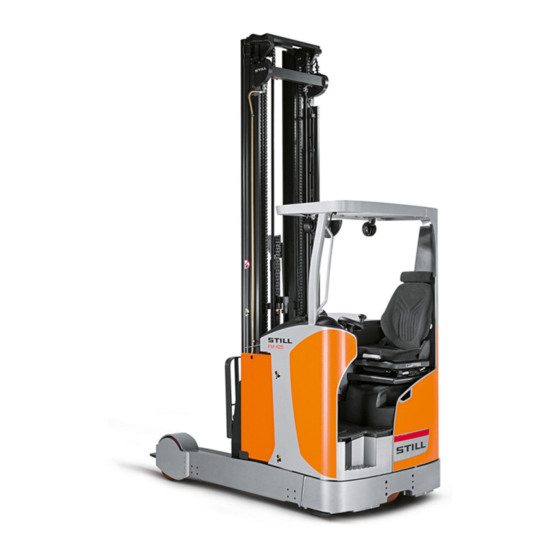
- Page 1 Original instructions Reach trucks FM-X, FM-X N, FM-X W, FM-X EW, Li-ion FM-X-10 FM-X-12 FM-X-14 FM-X-17 FM-X-20 FM-X-20 HD FM-X-25 1900 1901 1902 1903 1904 1905 1906 1907 1908 1909 1910 1914 1915 1916 1917 1918 1919 1920 1921 1922 50988078001 EN - 10/2018...
- Page 3 • Information on transport, initial commis- sioning and storage of industrial trucks Internet address and QR code The information can be accessed at any time by pasting the address https://m.still.de/vdma in a web browser or by scanning the QR code. 50988078001 EN - 10/2018...
-
Page 5: Table Of Contents
Table of contents Foreword Your truck ............2 General . - Page 6 Table of contents Modifications to the overhead guard and cabs ....... 31 Seat belt .
- Page 7 STILL SafetyLight (variant) ........
- Page 8 Table of contents Parking ............118 Parking the truck securely .
- Page 9 Table of contents Shock recognition (variant) ..........166 Active Load Stabilisation ALS (variant) .
- Page 10 Table of contents Impermissible use of the lithium-ion battery in the shock cold store (-45°C) ..210 Before entering the cold store ......... . . 211 Procedure in emergencies .
- Page 11 Table of contents Cleaning the electrical system ......... . 267 Cleaning load chains .
- Page 12 Table of contents Technical data Dimensions ............308 VDI datasheet for FM-X 10 / Li-ion (N), FM-X 12 / Li-ion (N)* .
-
Page 13: Foreword
Foreword... -
Page 14: Your Truck
Foreword Your truck Your truck General The truck described in these operating instruc- These operating instructions provide the tions corresponds to the applicable standards necessary information to do this. Read and and safety regulations. observe the information provided before commissioning the truck. This will prevent The trucks have been fitted with state-of-the- accidents and ensure that the warranty art technology. -
Page 15: Ec Declaration Of Conformity In Accordance With Machinery Directive
Foreword Your truck EC declaration of conformity in accordance with Machinery Directive Declaration STILL GmbH Berzeliusstraße 10 D-22113 Hamburg Germany We declare that the according to these operating instructions Industrial truck according to these operating instructions Model conforms to the latest version of the Machinery Directive 2006/42/EC. -
Page 16: Accessories
Foreword Your truck Accessories • Key for key switch (2 pieces), not for trucks with the FleetManager™ or "PIN code" variants • Key for cab (variant) • Hexagon socket wrench for emergency lowering (in the driver's compartment below the steering wheel) •... -
Page 17: Labelling Points
Foreword Your truck Labelling points BATTERIESERVICE Nächste Prüfung Ihr STILL Service STILL GmbH Hamburg Berzeliusstraße 10 22113 Hamburg Tel.: 01804/784 55 24 400-600 1000 10200 1150 9800 1110 1300 9500 1050 1200 1400 9300 1080 1240 1450 9000 1160 1320... -
Page 18: Nameplate
Foreword Your truck Warning sign: Do not place below the fork Decal information: FEM test / Do not place on the fork / Danger due to Decal information: FEM test (inspection shearing / Danger due to high fluid pressure sticker) Warning sign: Danger due to shearing Decal information: Nameplate Decal information: Battery version... -
Page 19: Production Number
Capacity equivalent: Weight: Manufacturer P/N: B-P/N: Address of manufacturer Custumer order no.: Still order no.: Date: Data/technical data Made in Germany Safety information Safety Advices for Lithium-Ion Batteries Do not crush. Do not heat or incinerate. Do not short-circuit. Do not dismantle. -
Page 20: Using The Truck
Foreword Using the truck 16 "Do not dispose with household waste" 17 "Recycling - recyclable material" Using the truck Commissioning Commissioning is the initial intended use of the truck. The necessary steps for the commissioning vary depending on the model and equipment of the truck. -
Page 21: Impermissible Use
Only lithium-ion battery chargers approved by STILL for use with this battery may be used. Impermissible use The operating company or driver, and not the manufacturer, is liable for any hazards caused by improper use. -
Page 22: Parking In Temperatures Below -10°C
Foreword Using the truck Driving on upward and downward gradients is permitted provided the defined data and specifications are observed; see the chapter entitled "Roadways". The truck is suitable for use in many different countries, ranging from those situated in the tropics to those in Nordic regions (temperature range: -10°C to +40°C). -
Page 23: Using Working Platforms
Foreword Using the truck Using working platforms WARNING The use of working platforms is regulated by na- tional law. The use of working platforms is only permitted by virtue of the jurisdiction in the country of use. – Observe national legislation. –... -
Page 24: Information About The Documentation
Foreword Information about the documentation Information about the documentation Documentation scope • Original operating instructions • Original operating instructions for attach- ments (variant) • Spare parts list • Depending on the truck equipment, "UPA" operating instructions may also be provided NOTE Refer to the additional information in the section entitled "Rules for the operating... -
Page 25: Supplementary Documentation
Foreword Information about the documentation The personnel responsible for operating and maintaining the equipment must be familiar with these operating instructions. The operating company must ensure that all users have received, read and understood these operating instructions. Safely store the complete documentation and pass on to the subsequent operating company when transferring or selling the truck. -
Page 26: Issue Date And Topicality Of The Operating Instructions
The issue date of these operating instructions can be found on the title page. STILL is constantly engaged in the further development of trucks. These operating instructions are subject to change, and any claims based on the information and/or illustrations contained in them cannot be asserted. -
Page 27: List Of Abbreviations
Foreword Information about the documentation NOTE For technical requirements that require special attention. ENVIRONMENT NOTE To prevent environmental damage. List of abbreviations NOTE This list of abbreviations applies to all types of operating instructions. Not all of the abbre- viations that are listed here will necessarily appear in these operating instructions. - Page 28 Foreword Information about the documentation Abbrevi- Meaning Explanation ation German authority for monitoring/issuing regulations for worker protection, environ- Gewerbeaufsichtsamt mental protection, and consumer protec- tion Transfer of data packets in wireless GPRS General Packet Radio Service networks ID no. ID number International Organization for Standard- International standardisation organisation ization...
-
Page 29: Defining Directions
Foreword Information about the documentation Defining directions General: • left (1) • right (2) Drive directions: • Travelling in the load direction (backwards) • Travelling in the drive direction (forwards) Movements of the reach carriage: • Extending the reach carriage (in the load direction) (5) •... -
Page 30: Schematic Views
Foreword Information about the documentation Schematic views View of functions and operating proce- dures At many points in this documentation, the operation of certain functions or operating procedures is explained. To illustrate these operations, schematic views of a reach truck are used. -
Page 31: Environmental Considerations
Foreword Environmental considerations Environmental considerations Packaging During delivery of the truck, certain parts are packaged to provide protection during transport. This packaging must be removed completely prior to initial start-up. ENVIRONMENT NOTE The packaging material must be disposed of properly after delivery of the truck. Disposal of components and batteries The truck is composed of different materials. -
Page 32: Fm-X
Foreword Environmental considerations 50988078001 EN - 10/2018... -
Page 33: Safety
Safety... -
Page 34: Definition Of Responsible Persons
Safety Definition of responsible persons Definition of responsible persons Operating company The operating company is the natural or legal person or group who operates the truck or on whose authority the truck is used. The operating company must ensure that the truck is only used for its proper purpose and in compliance with the safety regulations set out in these operating instructions. -
Page 35: Drivers
Safety Definition of responsible persons regarding the industrial truck to be tested and the risk being assessed Drivers This truck may only be driven by suitable per- sons who are at least 18 years of age, have been trained in driving, have demonstrated their skills in driving and handling loads to the operating company or an authorised rep- resentative, and have been specifically in-... - Page 36 Safety Definition of responsible persons DANGER The use of drugs, alcohol or medications that affect reactions impair the ability to drive the truck! Individuals under the influence of the aforementio- ned substances are not permitted to perform work of any kind on or with the truck. Prohibition of use by unauthorised persons The driver is responsible for the truck during...
-
Page 37: Basic Principles For Safe Operation
Safety Basic principles for safe operation Basic principles for safe operation Insurance cover on company premises In many cases, company premises are restricted public traffic areas. NOTE The business liability insurance should be reviewed to ensure that, in the event of any damage caused in restricted public traffic areas, there is insurance cover for the truck in respect of third parties. - Page 38 Safety Basic principles for safe operation Product-specific dangers posed by the lithium-ion battery Lithium-ion battery Battery group 4.1 Battery group 4.2, 4.3 Hot area on the brake resistor (position depends on the battery group; observe the warning sign Safety valve (position depends on the battery group) WARNING Risk of burns due to hot surfaces!
- Page 39 Permissible lithium-ion batteries – Use only lithium-ion batteries that have been approved by STILL for use with this truck. The dimensions of the battery must precisely correspond to the dimensions of the battery frame in the truck. The...
- Page 40 Safety Basic principles for safe operation in accordance with the manufacturer's operating instructions for the battery. Declaring the use of lithium-ion batteries The health and safety representative and the workforce must also be informed that trucks with lithium-ion batteries are being used. We recommend that the operating company informs the local fire brigade of the planned use of trucks fitted with lithium-ion batteries.
-
Page 41: Changes And Retrofitting
Additional attachments (e.g. terminals, printers, mirrors) in the driver's compartment area can restrict the driver's field of vision. – Only install attachments (variants) that have been specifically approved by STILL in accor- dance with the safety regulations. 50988078001 EN - 10/2018... - Page 42 Safety Basic principles for safe operation When carrying out welding work on the truck, it is essential that the battery and all connections to the electronic control cards are disconnected. Contact the authorised service centre on this matter. In the event of the manufacturer going into liquidation and the company not being taken over by another legal person, the operating company can make changes to the truck.
-
Page 43: Modifications To The Overhead Guard And Cabs
Safety Basic principles for safe operation Modifications to the overhead guard and cabs DANGER Work on the overhead guard or on the weather protection cab/cold store cab reduces its stability. A falling load or the truck tipping over can cause the modified chassis, bodywork and fittings to fail. -
Page 44: Safety Information For Fm-X Wide, Extra Wide (W, Ew)
STILL. CAUTION Installation and/or use of such products may there- fore have a negative impact on the design features of the truck and thus impair active and/or passive driving safety. -
Page 45: Damage, Defects And Misuse Of Safety Systems
Safety Basic principles for safe operation Damage, defects and misuse of safety systems Damage or other defects on the truck or attachment must be reported to the supervisor or responsible fleet manager immediately so that they can have the defect rectified. Trucks and attachments that are not functional or safe to drive may not be used until they have been properly repaired. -
Page 46: Medical Equipment
Safety Basic principles for safe operation • Only use wheels approved by the manufac- turer. • Only use high-quality products. When changing wheels, always ensure that this does not cause the truck to tilt to one side (e.g. always replace right and left wheels at the same time). -
Page 47: Exercise Caution When Handling Gas Springs And Accumulators
Safety Basic principles for safe operation Exercise caution when handling gas springs and accumulators WARNING Gas springs are under high pressure. Improper removal results in an elevated risk of injury. For ease of operation, various functions on the truck can be supported by gas springs. Gas springs are complex components that are subject to high internal pressures (up to 300 bar). - Page 48 Safety Basic principles for safe operation picked up. These other loading units then fall over when the load is raised. – For help with selecting the correct fork arms, contact the authorised service centre. 50988078001 EN - 10/2018...
-
Page 49: Residual Risk
Safety Residual risk Residual risk Residual dangers, residual risks Despite careful working and compliance with standards and regulations, the occurrence of other risks when using the truck cannot be entirely excluded. The truck and all other system components comply with current safety requirements. Nevertheless, even when the truck is used for its proper purpose and all instructions are followed, some residual risk cannot be... -
Page 50: Special Risks Associated With Using The Truck And Attachments
Safety Residual risk The manufacturer is not held responsible for accidents involving the truck caused by the failure of the operating company to comply with these regulations either intentionally or carelessly. Stability The stability of the truck has been tested to the latest technological standards and is guaran- teed provided that the truck is used properly and according to its intended purpose. - Page 51 Safety Residual risk time the truck is used in a manner that falls outside the scope of normal use, and in cases where the driver is not certain that he can use the truck correctly and without the risk of acci- dents.
-
Page 52: Overview Of Hazards And Countermeasures
Safety Residual risk Overview of hazards and counter- measures NOTE This table is intended to help evaluate the hazards in your facility and applies to all drive types. It does not claim to be complete. – Observe the national regulations for the country in which the truck is being used. - Page 53 Safety Residual risk Hazard Measure Check note Notes √ Complete - Not applicable Impermissible usage Issuing of operating German Ordinance on (improper usage) instructions Industrial Safety and Health (BetrSichV) and German Health and labour protection law (ArbSchG) Written notice of German Ordinance on instruction to driver Industrial Safety and...
- Page 54 Safety Residual risk Hazard Measure Check note Notes √ Complete - Not applicable When charging the Note the German Association for traction battery Ordinance on Electrical, Electronic Industrial Safety and and Information Health (BetrSichV), Technologies (VDE) the operating regulation 0510: In instructions and the particular German Engineering...
-
Page 55: Danger To Employees
Safety Residual risk Danger to employees According to the German Ordinance on Indus- trial Safety and Health (BetrSichV) and labour protection law (ArbSchG), the operating com- pany must determine and assess hazards during operation, and establish the labour protection measures required for employ- ees (BetrSichVO). -
Page 56: Safety Tests
Safety Safety tests Safety tests Carrying out regular inspections on the truck The operating company must ensure that the truck is checked by a specialist at least once a year or after particular incidents. As part of this inspection, the technical con- dition of the truck must be completely tested with regard to accident safety. -
Page 57: Safety Regulations For Handling Consumables
Safety Safety regulations for handling consumables The exact procedure for this insulation testing is described in the workshop manual for this truck. NOTE The truck's electrical system and drive batte- ries must be checked separately. Test values for the drive battery Recommended Nominal voltage Component... -
Page 58: Oils
Safety Safety regulations for handling consumables Oils DANGER Oils are flammable! – Follow the statutory regulations. – Do not allow oils to come into contact with hot engine parts. – No smoking, fires or naked flames! DANGER Oils are toxic! –... -
Page 59: Hydraulic Fluid
Safety Safety regulations for handling consumables ENVIRONMENT NOTE Oil is a water-polluting substance! Always store oil in containers that comply • with the applicable regulations. Avoid spilling oils. • Spilt oil should be removed immediately • with oil-binding agents and disposed of according to the regulations. -
Page 60: Battery Acid
Safety Safety regulations for handling consumables ENVIRONMENT NOTE Hydraulic fluid is a water-polluting substance. Always store hydraulic fluid in containers • that comply with regulations Avoid spills • Spilt hydraulic fluid should be removed • immediately with oil-binding agents and disposed of according to the regulations Dispose of old hydraulic fluid according to •... -
Page 61: Brake Fluid
Safety Safety regulations for handling consumables Brake fluid WARNING Brake fluid is poisonous! – Avoid swallowing. In the event of swallowing, do not induce vomiting. Rinse out your mouth thoroughly with water and ask a doctor for advice. – Avoid aerosolisation and inhala- tion. -
Page 62: Disposal Of Consumables
Safety Safety regulations for handling consumables ENVIRONMENT NOTE Brake fluid is a water pollutant! Always store brake fluid in containers • complying with the regulations.. Do not spill brake fluid. • Spilt brake fluid must be removed immedia- • tely using an oil binding agent and disposed of in accordance with regulations Dispose of old brake fluid according to the •... -
Page 63: Commissioning The Fleetmanager™ (Variant)
Safety Commissioning the FleetManager™ (variant) Commissioning the FleetManager™ (variant) Activating the access control after delivery of the truck CAUTION Danger associated with use by unauthorised per- sons The FleetManager™ regulates the access authori- sation to the truck. To activate the access control, the FleetManager must be put into operation im- mediately following delivery. - Page 64 Safety Emissions additional units etc. may produce different values. Noise emissions The values were determined using the mea- suring procedures from the EN 12053 stan- dard (noise measurement for industrial trucks based on EN 12001 and EN ISO 3744 and the requirements of EN ISO 4871).
- Page 65 – Observe the safety regulations for handling the battery. Radiation In accordance with the guidelines DIN EN 62471:2009-03 (VDE 0837-471:2009- 03), the STILL SafetyLight (variant) is as- signed to risk group 2 (medium risk) due to its photobiological hazard potential. 50988078001 EN - 10/2018...
- Page 66 Safety Emissions 50988078001 EN - 10/2018...
-
Page 67: Overviews
Overviews... -
Page 68: Overview
Overviews Overview Overview Overhead guard Battery Driver's compartment Side support (tilt protection) Lift mast Control compartment Fork arms Drive wheel Load wheel Step Battery frame 50988078001 EN - 10/2018... -
Page 69: Overview Of The Driver's Compartment
Overviews Overview of the driver's compartment NOTE The truck equipment may differ from the equipment shown. Overview of the driver's compartment 2 3 4 Steering wheel Display and operating unit Button for speed limitation, creep speed Cup holder for max. 1.5-l bottles (variant) Operating devices for hydraulic and traction Electrical seat adjustment push button... -
Page 70: Shelves And Cup Holders
Overviews Shelves and cup holders Shelves and cup holders WARNING Objects may fall into the footwell and obstruct the pedals, which poses a risk of accident! Objects to be stored must be of the correct size so that they do not fall from the shelves (1, 4) or out of the cup holder (2). -
Page 71: Operating Devices And Display Elements
Overviews Operating devices and display elements Operating devices and display elements Display and operating unit Display of the operating statuses Keypad for lift height preselection (variant) or PIN code access (variant) Keypad for onboard diagnostics, parame- terising Drive programme button (P1-P4) Blue-Q button Parking brake button 50988078001 EN - 10/2018... -
Page 72: Operating Status Displays On The Display And Operating Unit
20% of the nominal capacity, only the Battery charging state last segment will still flash. A hydraulic limitation and/or driving limitation can be implemented as an option. The hydraulic limitation and/or driving limitation must be activated by the authorised service centre. -
Page 73: Display Messages
Overviews Operating devices and display elements Item no. Display Comment Function assistant, centre position for transition shift Function assistant, centre position for tilting - Operating hours, error messages, drive The meter displays up to 99,999.9 operat- profile, information text ing hours. Acknowledge button Actuation required for further functioning Information... - Page 74 LED height sensor and reflector. Remove obstacles. reflector. Then fully lower the fork to reference the system. ● If the message is still displayed after cleaning, contact your authorised service centre. ● Emergency off switch of the Switch off the truck. Unlock the truck is actuated emergency off switch.
- Page 75 ● Traction dynamics and position for 2 seconds hydraulic speed are restricted ● Switch off the truck ● Lithium-ion battery is in ● If the message is still emergency operation displayed after restarting, ● Driving speed and hydraulic contact your authorised service...
- Page 76 ● Check the battery cable and battery plug ● No communication with the ● Restart the truck lithium-ion battery S5951 ● If the message is still ● All truck functions are displayed after restarting, disabled contact your authorised service centre ●...
-
Page 77: Entering Truck Operating Data Via The Display And Operating Unit
Overviews Operating devices and display elements Entering truck operating data via the display and operating unit Authorisation levels The authorisation levels determine which operating data and functions the user can access. The higher the authorisation level, the more comprehensive the access to truck operating data. - Page 78 Overviews Operating devices and display elements Level 3 (authorised service centre) Access: Press OK and ESC for 4 seconds and enter the password for level 3 Authorisations: Maintenance interval PIN for remote data transfer via SIM card Delete error list Accessing the main menu without a password (authorisation level 1) First of all, press the OK button to open the...
- Page 79 Overviews Operating devices and display elements If the password is invalid, a corresponding message appears on the display and operat- ing unit. PASSWORD NOT VALID The message appears for three seconds and then the display and operating unit shows the input screen for the password again. The password can be entered again.
- Page 80 Overviews Operating devices and display elements Entering operating data in the main menu The menus on the display and operating unit are controlled using the OK button (1), ESC button (3) and arrow buttons (2). – Press the arrow buttons to navigate through the menus –...
- Page 81 Overviews Operating devices and display elements Authori- sation Main menu Submenu (level) Edit/select Comment CONFIGU- RATION VX.XX UNITS DISTANCE miles LOAD CUSTOMER ERROR LIST MODE SERVICE A–Z, *: all DEVICE devices current error TYPE since reset since deletion Error e.g. A 12 X XX XX Teach-in...
-
Page 82: Lithium-Ion Battery Display
Overviews Operating devices and display elements Lithium-ion battery display The lithium-ion battery has its own display. The display shows information about the error status (1), the temperature (2) and the charging status (3) of the lithium-ion battery. – See the "Display" chapter in the operating instructions provided by the battery manu- facturer, "BMZ". -
Page 83: Joystick 4Plus
Overviews Operating devices and display elements Joystick 4Plus "Transition shift" slider "Transition shift/tilt centre position" push Shift button "F" (auxiliary hydraulics con- button (variant) troller) Reserve Drive direction switch Pictograms for operation of the 5th and 6th Joystick, "lifting/lowering" function hydraulic function (variant) Joystick, "shifting"... -
Page 84: Fingertip
Overviews Operating devices and display elements Fingertip "Lift/lower" operating lever "Transition shift/tilt centre position" push "Shift" operating lever button (variant) "Tilt" operating lever Reserve "Transition shift" operating lever "Auxiliary hydraulics" push button (variant) Emergency off switch Drive direction switch "Enable" push button (variant) Signal horn button "Load measurement"... -
Page 85: Operation
Operation... -
Page 86: Testing And Activities Before Daily Use
Operation Testing and activities before daily use Testing and activities before daily use Visual inspections and function checking DANGER Risk of explosion if hydrogen builds up in the cab! If the truck is equipped with a cab, hy- drogen from the battery compartment can ingress into the cab through un- sealed bores. - Page 87 Operation Testing and activities before daily use CAUTION Risk of component damage! A deformed or damaged battery male connector can cause overheating and related consequential damage. – Check the battery male connector for damage. – If necessary, have the battery male connector replaced by the authorised service centre.
- Page 88 Operation Testing and activities before daily use Component Course of action Perform a visual inspection for wear and damage. Make sure that only approved tyre types are used (see the chapter entitled " Technical data/Wheels and tyres"). Wheels, tyres In the event of uneven tyre wear on the load wheels, change both tyres.
-
Page 89: Climbing Into And Out Of The Truck
Component Course of action Perform a visual inspection for integrity. Ensure cleanliness. Make sure that the antistatic belt is still long enough Antistatic belt, corona electrode to touch the ground. The discharge wires of the corona electrode must not touch the ground. The wires discharge the energy to the air. - Page 90 Operation Testing and activities before daily use WARNING Risk of injury when jumping out of the truck! If the driver jumps out the truck while it is moving, he or she could fall under the truck or be crushed by an obstacle.
-
Page 91: Adjusting The Msg 65/Msg 75 Driver's Seat
Operation Testing and activities before daily use Adjusting the MSG 65/MSG 75 driver's seat WARNING Risk of accident from sudden adjustment of the seat or of the seat backrest! If the seat or the seat backrest is adjusted uninten- tionally, it can lead to uncontrolled movements by the driver. - Page 92 Operation Testing and activities before daily use Moving the driver's seat – Lift the lever (1) and hold. – Push the driver's seat into the desired position. – Release the lever. – Ensure that the driver's seat is securely engaged. Adjusting the seat backrest Do not put pressure on the seat backrest while disengaging it.
- Page 93 Operation Testing and activities before daily use Adjusting the seat suspension NOTE The MSG 75 seat is equipped with electric air suspension that is activated using an electric switch instead of a lever (3). The driver's seat can be adjusted to suit the weight of the individual driver.
- Page 94 Operation Testing and activities before daily use Adjusting the backrest extension (variant) – Adjust the backrest extension (6) by pulling it out or pushing it into the desired position. To remove the backrest extension, move it past the end stop by jolting it upwards. Switching the seat heater (variant) on and off NOTE...
-
Page 95: Adjusting The Steering Column
Operation Testing and activities before daily use Adjusting the horizontal suspension (variant) – Push the lever (8) in sideways and slide the driver's seat to the locked position. To release, push the lever outwards. Using the lever (9), the driver can adjust the hardness in several levels. -
Page 96: Filling The Washer System (Variant)
Operation Testing and activities before daily use Filling the washer system (variant) The washer reservoir is located behind the driver's seat in the weather protection cab. The filling opening is accessible from above. – Open the washer system filler cap (1). –... -
Page 97: Switching On The Key Switch
Operation Testing and activities before daily use Switching on the key switch WARNING Before switching on the key switch, all tests prior to commissioning must be performed without any defects being detected. – Carry out checks prior to commissioning (refer to the chapter entitled "Checks and tasks to be carried out prior to commissioning"). - Page 98 Operation Testing and activities before daily use Displays after the switch-on process (for trucks with default options) NOTE Depending on the truck equipment, further information may be visible on the display and operating unit. Battery charge(1) The usable battery charge is shown in the display field.
-
Page 99: Access Authorisation With Pin Code (Variant)
Operation Testing and activities before daily use direction is only selected when the drive direction switch has been actuated once. Operating hours(3) The current value of the hour meter is shown in the display field. Drive programme(4) The current drive programme (1-4) is shown in the display field. -
Page 100: Operating The Signal Horn
Operation Testing and activities before daily use Operating the signal horn NOTE The signal horn is used to warn people against imminent danger or to announce your intention to overtake. – Push the signal horn button (1). The signal horn sounds. Checking the brake system for correct function DANGER... - Page 101 Operation Testing and activities before daily use The truck must decelerate slightly. Checking the reverse brake – Accelerate the truck without a load in a clear area; see "Driving" chapter. – Change the drive direction in inching mode; see the chapter entitled "Selecting the drive direction".
-
Page 102: Checking The Steering System For Correct Function
Operation Testing and activities before daily use Checking the steering system for correct function – Operate the steering wheel (1). The steer- ing must be continuous and move freely. NOTE In the "180° steering" variant, the drive's maximum steering angle is ±90°. 5060_003-031 Checking the emergency off function –... -
Page 103: Checking The "Automatic Tilting Centre Position" (Variant) For Correct Function
Operation Testing and activities before daily use Checking the "automatic tilting centre position" (variant) for correct function NOTE Perform the "Automatic tilt to centre position" function check each time before using the truck. The driver can use the "automatic tilt to centre position"... -
Page 104: Lighting
(such as drive lanes, high racks), as well as at blind junctions. STILL SafetyLight is mounted on a support on the overhead guard such that it is not affected by jolts and vibrations. It projects one or more... -
Page 105: Switching The Working Spotlights (Variant) On And Off
Operation Lighting Switching the working spotlights (variant) on and off There is an option to have the truck fitted with one or several working spotlights (1) to improve illumination of the working area. – Switch on the truck. – Push the button (2) for the working spot- lights. -
Page 106: Efficiency And Drive Modes
Operation Efficiency and drive modes Efficiency and drive modes Blue-Q efficiency mode The Blue-Q efficiency mode affects both the drive unit and the activation of the additional consumers and reduces the truck's energy consumption. If the efficiency mode has been activated, the acceleration behaviour of the truck changes to make acceleration more moderate. - Page 107 DANGER The stability limits defined by the laws of physics are still in effect even when the "reduction of speed when turning" function is active. There is a risk of tipping! – Before using this function, familiarise yourself with the change to the truck's driving and steering characteristics.
-
Page 108: Driving
Operation Driving DANGER Risk of tipping due to change in vibration characte- ristics of the load! If the controller is switched off or fails, the speed of the hydraulic functions will no longer be reduced. – Always adapt the use of the hydraulic functions to suit the situation. - Page 109 There is a risk of accident! – Do not use devices during travel or when hand- ling loads. – Set the volume so that warning signals can still be heard. WARNING In areas where the use of mobile phones is prohi- bited, it is absolutely not permitted to use a mobile phone or radio telephone.
-
Page 110: Roadways
Operation Driving If this is not possible, a second person acting as a guide must walk in front of the truck. In this case, the driver must only move at walking pace and with extra care. The truck must be stopped immediately if eye contact with the guide is lost. - Page 111 Operation Driving The truck may only be used on roadways that do not have excessively sharp bends, excessively steep gradients or excessively narrow or low entrances. Driving on ascending and descending gradients WARNING Driving up and down longer gradients may result in the drive unit overheating or the minimum specified braking values being exceeded.
- Page 112 Operation Driving Condition of the roadways Roadways must be sufficiently firm, smooth and even. The surface must be free from dirt and fallen objects. Drainage channels, level crossings and similar obstacles must be evened out, and if necessary, ramps must be provided so that trucks can drive over these obstacles with as few bumps as possible.
-
Page 113: Side Chassis Supports
Operation Driving Side chassis supports Side chassis supports (1) on the rear left and right of the truck support the truck if it tips to the side. The permissible distance "X" for the ground clearance of the chassis supports (2) is noted on the load capacity diagram on the truck. - Page 114 Operation Driving Enabling the truck functions using the foot switch The truck's drive function and hydraulic functions are enabled only when the driver actuates the foot switch (1). The left foot is therefore protected within the contour of the truck. Trucks with one accelerator pedal The hydraulic functions are only enabled if: •...
- Page 115 Operation Driving • One of the accelerator pedals is then actuated • The switches are all functioning correctly NOTE The parking brake is released once one of the accelerator pedals is actuated slightly. Enabling the truck functions using the seat switch The seat switch monitors whether or not a driver is seated on the driver's seat.
-
Page 116: Setting The Drive Programme
Operation Driving Setting the drive programme Setting The driving and braking characteristics of the drive can be set on the display and operating unit. Four different drive programmes can be set. Depending on the drive programme selected, different driving characteristics are applied in relation to the maximum speed, acceleration behaviour* and deceleration behaviour**. -
Page 117: Selecting The Drive Direction
Operation Driving Selecting the drive direction The desired drive direction of the truck must be selected using the drive direction switch before attempting to drive. When the truck is switched on, there is initially no drive direction selected. The drive direction indicator on the display and operating unit shows the "neutral position"... -
Page 118: Actuating The Drive Direction Switch, Joystick 4Plus
Operation Driving NOTE When the driver leaves the seat, the direction switch is set to neutral. To drive, the direction switch must be actuated again. Actuating the drive direction switch, joystick 4Plus – For "travelling in the load direction", press the drive direction switch (1)up. -
Page 119: Starting Drive Mode, Single-Pedal Version
Operation Driving Starting drive mode, single-pedal version DANGER Being trapped under a rolling or tipping truck could cause fatal injuries. – Sit down on the driver's seat. – During work, ensure that you have a secure grip on the truck and a stable seat position. Hold on tight to the steering wheel with your left hand. - Page 120 The truck cannot be driven again until the accelerator pedal has been released and then actuated again. If the truck still cannot be operated, park it securely and contact your authorised service centre. 50988078001 EN - 10/2018...
-
Page 121: Starting Drive Mode, Dual-Pedal Version (Variant)
Operation Driving Starting drive mode, dual-pedal version (variant) DANGER Being trapped under a rolling or tipping truck could cause fatal injuries. – Sit down on the driver's seat. – During work, ensure that you have a secure grip on the truck and a stable seat position. Hold on tight to the steering wheel with your left hand. - Page 122 The truck cannot be driven again until the accelerator pedal has been released and then actuated again, provided that the electrical fault has been corrected. If the truck still cannot be operated, park it securely and contact your authorised service centre.
-
Page 123: Operating The Service Brake
Operation Driving Operating the service brake Electrical braking recovers energy for the battery. This results in a longer operating time between the charging processes and less wear to the brakes. The electric brake converts the acceleration energy of the truck into electrical energy as soon as the accelerator pedal is released. -
Page 124: Applying The Electromagnetic Parking Brake
Operation Driving Applying the electromagnetic parking brake DANGER There is a risk of fatal injury from being run over if the truck rolls away. – Only leave the truck once the parking brake has been applied. – The truck must not be parked on a slope. –... - Page 125 Operation Driving – Sit on the driver's seat. – Select the drive direction (single-pedal version only). – Press the foot switch. – Actuate the accelerator pedal. The parking brake is released automatically and audibly, and the symbol on the display and operating unit disappears.
-
Page 126: Steering
Operation Driving The symbol (2) is shown in the display and operating unit. Automatic application of the parking brake Cause Effect The parking brake is applied immediately and audibly. The symbol (2) is shown briefly on the If the truck is switched off: display and operating unit until the control units switch off. -
Page 127: Emergency Operation Of The Reach Measurement System
Operation Driving 180° steering (variant) The steering wheel has no mechanical stops and can be continuously turned. The path of travel (1) is determined by turning the steering wheel. The maximum steering angle of the steered wheel is 90° to each side. - Page 128 Operation Driving Effects of emergency operation • The position of the reach carriage is no longer shown in the display • The "shift" function is performed at a reduced speed • The reach carriage moves abruptly into the end stops •...
- Page 129 Operation Driving Checking the reach measurement system for foreign objects DANGER Risk of injury due to movement of the reach carriage during the test Switch the truck off before the test. Disconnect the battery male connector. The reach measurement system consists of the reach travel sensor (1) and a reference bar (2).
-
Page 130: Parking
Operation Parking Parking Parking the truck securely DANGER There is a risk of fatal injury from being run over if the truck rolls away. – The truck must not be parked on a slope. – In emergencies, secure with wedges on the side facing downhill. -
Page 131: Lifting
Operation Lifting Lifting Lifting system variants The movement of the fork carriage and the lift mast heavily depends on the following equipment: • The lift mast fitted on the truck; see the chapter entitled "Lift mast versions" • The operating device that is used to control the hydraulic functions;... -
Page 132: Lifting System Operating Devices
Operation Lifting Triplex lift mast (variant) During lifting, the inner lift cylinder raises the fork carriage up to the free lift (2) and then the outer lift cylinders raise the inner lift mast straight up to the max. height (3). Lifting system operating devices The operation of the lifting system depends on the operating devices that are fitted on the... -
Page 133: Joystick 4Plus Lifting System
Operation Lifting Joystick 4Plus lifting system A / B Lowering/lifting the fork carriage E / F Transition shift (variant) C / D Tilting the lift mast (variant) G / H Shifting DANGER Reaching or climbing between moving parts of the truck (e.g. - Page 134 Operation Lifting In this version, the hydraulic functions are controlled using the joystick 4Plus. The pictogram (1) shows the basic hydraulic functions and how they are controlled using the joystick. The pictogram (2) shows the 3rd and 4th function and their operation. Lifting/lowering the fork carriage To lift the fork carriage: –...
- Page 135 Operation Lifting Tilting the lift mast or fork carriage (variant) Depending on the truck equipment, either the entire lift mast is tilted or just the fork carriage (fork tilt device). To tilt the lift mast backwards: – Push the rocker button (2) towards " ".
-
Page 136: Fingertip Lifting System
Operation Lifting Shifting To extend the reach carriage: – Push the joystick (4) in the direction of " ". To retract the reach carriage: – Push the joystick (4) in the direction of " ". NOTE The pictograms on the base of the joystick show the direction of movement for the corresponding hydraulic function. - Page 137 Operation Lifting DANGER Reaching or climbing between moving parts of the truck (e.g. lift mast, sideshifts, working equipment, load carrying devices etc.) can lead to serious injury or death and is therefore prohibited. – Always observe the safety regulations for hand- ling loads;...
-
Page 138: Automatic Lift Cut Out (Variant)
Operation Lifting – Push the "transition shift" operating lever (4) forwards. Transition shift to the right: – Pull the "transition shift" operating lever (4) backwards. NOTE The pictograms on the operating levers show the direction of movement for the corresponding hydraulic function. Automatic lift cut out (variant) The automatic lift cut-out interrupts the lifting of the load at a certain height. - Page 139 Operation Lifting Lift cut-out limit stop (not acknowledge- able) The lift cut-out limit stop prevents the lift mast being extended up to the maximum possible lift height. This helps to prevent lift mast collisions, for example, if the ceiling of the hall is lower than the maximum lift height of the truck.
-
Page 140: Reach-Lower Lock (Variant)
Operation Lifting Reach-lower lock (variant) The reach/lower lock prevents the load forks from being lowered between the running wheel beams for the entire time that the reach carriage is in the retracted position. As a result, wide loads cannot accidentally come to rest on the running wheel beams during lowering and become unstable. -
Page 141: Automatic Centre Position (Variant)
Operation Lifting Automatic centre position (variant) Automatic transition shift centre position The driver can use the "automatic transition shift centre position" function to position the transition shift in the centre automatically. To do this, the pushbutton must be actuated until the function switches off automatically. Depending on the truck version, either only the fork carriage (sideshift) or the entire lift mast (mast traversing) is positioned. - Page 142 Operation Lifting Automatic tilting centre position The driver can use the "automatic tilt to centre position" function to change the tilt of the fork arms to 0° automatically. To do this, the pushbutton must be actuated until the function switches off automatically. Depending on the truck version, either only the fork carriage (fork tilter) or the entire lift mast (mast tilter) is positioned.
-
Page 143: Speed Limitation Safety Function
Operation Lifting Speed limitation safety function WARNING There is always an increased risk of the truck tipping if it is driven with a raised load. The system is a support for the driver when placing items into stock and removing items from stock. The responsibility for safe operation and complying with safety regulations remains with the driver. - Page 144 Operation Lifting WARNING There is a risk of injury when changing the fork arms; the fork arms' weight could cause them to fall on your legs, feet or knees. The space to the left and right of the fork is a danger area. –...
- Page 145 Operation Lifting Removal – Extend the reach carriage fully. – Select a pallet corresponding to the fork arm size. – Position the pallet to the left or right of the fork carriage. – Raise the fork carriage until the lower edges of the fork arms are approx.
-
Page 146: Fork Extension (Variant)
Operation Lifting Fork extension (variant) DANGER There is a risk of being run over if the truck rolls away, and therefore a danger to life. – Do not park the truck on a gradient. – Apply the parking brake. – Change the fork extension in a separate, safe location on a level surface. -
Page 147: Load Backrest (Variant)
Operation Lifting – Remove the securing bolt from the fork extension (1). – Push the fork extension onto the fork arms until it is flush with the fork back. – Insert the securing bolts located behind the fork back fully into the fork extension. –... -
Page 148: Working Platforms
Operation Lifting Working platforms The use of working platforms in conjunction with industrial trucks is regulated by national law. This legislation should be observed. The use of working platforms is only permitted by virtue of the legislation in the country of use. Before using working platforms, consult your national regulatory authorities. - Page 149 Operation Lifting Load chains not under tension DANGER Danger caused by a falling load! – Make sure that the chains do not become slack when lowering the load. Slack chains can be caused by the following: • The fork carriage or the load is resting on the racking •...
-
Page 150: Handling Loads
Operation Handling loads Handling loads Safety regulations when handing loads The safety regulations for handling loads are shown in the following sections. DANGER There is a risk to life caused by falling loads or if parts of the truck are being lowered. –... - Page 151 Operation Handling loads WARNING The figures show examples. Only the capacity rating plates on the truck are valid! The attachment of additional weights to increase load capacity is prohibited. DANGER Risk to life from the truck losing stability! Never exceed the maximum loads shown! These values apply to compact and homogeneous loads.
-
Page 152: Picking Up Loads
Operation Handling loads Example Weight of load to be lifted (1) Permissible lift height (2) Load distance from fork back (3) WARNING Risk of accident from the truck losing stability! The permissible loading of the attachments (va- riant) and the reduced load capacity of the combi- nation of truck and attachment must not be excee- ded. - Page 153 Operation Handling loads If possible, the load should rest on the back of the fork. The load must not protrude too far over the fork tips, nor should the fork tips protrude too far out from the load. Loads must be picked up and transported as close to the middle as possible.
-
Page 154: Danger Area
Operation Handling loads Danger area The danger area is the area in which people are at risk due to the movements of the truck, its working equipment, its load-carrying equipment (e.g. attachments) or the load. Also included are the areas where loads could fall or working equipment could fall or be lowered. -
Page 155: Transporting Pallets
Operation Handling loads Transporting pallets As a rule, loads (e.g. pallets) must be transpor- ted individually. Transporting multiple loads at the same time is only permitted: • when instructed by the supervisor and • when the technical requirements have been met. -
Page 156: Picking Up A Load
Operation Handling loads Instructions for transporting suspended loads: • Swinging of the load is to be prevented by using the proper driving speed and driving manner (careful steering, braking). • Hanging loads must be coupled to the truck in such a way that the harness cannot shift or release unintentionally, and cannot be damaged. - Page 157 Operation Handling loads ified aisle width is not reduced by protruding parts. – Approach the racking carefully, brake gently and stop just in front of the racking. – Tilt the fork arms or lift mast until the fork arms are horizontal. –...
- Page 158 Operation Handling loads – Retract the reach carriage fully. – Release the brake. DANGER Risk of accident! – Beware of any people in the danger area. – Ensure that the roadway on the drive side is clear. Move backwards carefully and slowly until the load is clear of the racking.
-
Page 159: Transporting Loads
Operation Handling loads – Lower the load carefully while maintaining ground clearance. Lower wider loads that do not fit between the load wheel posts only until they are not resting on the posts. – Tilt the fork tips or lift mast fully to the drive side into the driving position. - Page 160 Operation Handling loads DANGER The higher a load is lifted, the less stable it beco- mes. The truck can tip over or the load can fall, increasing the risk of accident! Driving with a raised load and the lift mast tilted forward is not permitted.
-
Page 161: Setting Down Loads
Operation Handling loads – Never drive with a load protruding on one side or with a load shifted to the side (sideshift). The centre of gravity of the load must always be positioned on the longitudinal axis of the truck. Setting down loads DANGER Risk of accident due to changed moment of tilt! - Page 162 Operation Handling loads – Raise the load to just above the required height. – If necessary operate the sideshift to position the load centrally. – Extend the reach carriage fully. – Release the brake. – Drive up to the racking so the truck chassis is as close as possible until the load can be lowered into its final position.
-
Page 163: Driving On Upward And Downward Gradients
Operation Handling loads Driving on upward and downward gradients DANGER Danger to life! On upward and downward gradients, the load must be carried facing uphill. It is only permitted to drive on upward and down- ward gradients if they are marked as traffic routes and can be used safely. - Page 164 Operation Handling loads Determining the total actual weight – Park the truck securely. – Determine the unit weights by reading the truck nameplate and, if necessary, the attachment (variant) nameplate and, if Type-Modèle-Typ / Serial no.-No. de série-Serien-Nr. / year-année-Baujahr necessary, by weighing the load to be lifted.
-
Page 165: Attachments
Fitting attachments If the truck is equipped with an integrated attachment (variant) at the factory, the specifi- cations in the STILL operating instructions for integrated attachments must be observed. If attachments are fitted at the place of use, the specifications in the operating instructions of the attachment manufacturer must be observed. - Page 166 Operation Attachments DANGER There is risk to life caused by a falling load! Attachments that hold the load by exerting pressure on it (e.g. clamps) must be controlled additionally by a second operating function (lock) that is actuated to prevent an unintentional release of the load. If such an attachment is retrofitted, a second opera- ting function for actuation must also be retrofitted.
-
Page 167: Releasing The Pressure From The Auxiliary Hydraulics
Operation Attachments Load capacity with attachment The permissible load capacity of the attach- ment and the allowable load (load capacity and load moment) of the truck must not be ex- ceeded by the combination of attachment and payload. The specifications of the manufac- turer and supplier of the attachment must be complied with. -
Page 168: General Instructions For Controlling Attachments
Operation Attachments After approx. one second, all of the assistance arrows (1) will flash. DANGER When activating the valves for the purpose of depressurising the hydraulic lines, unexpected hydraulic movements may occur. The "release the pressure from the hydraulics" truck function can be used to depressurise the entire hydraulic system. -
Page 169: Controlling Attachments (Variant) Using The Joystick 4Plus (5Th/6Th Hydraulic Function
Operation Attachments WARNING Use of attachments can give rise to additional hazards such as a change in the centre of gravity, additional danger areas etc. Attachments must only be used for their intended purpose as described in the relevant operating instructions. - Page 170 Operation Attachments – Actuate the shift button "F"(1). – Move the joystick in the direction of the arrow "4" or "5". Or: – Move the vertical rocker button (6) to the left or right. NOTE The movement/action of these additional functions can be found in the operating instructions of the fitted attachment.
- Page 171 Operation Attachments No. Operating device Function of the attachment Joystick + shift Fork prong positioner: close/open button "F" Vertical rocker Fork positioner: forwards/backwards button + shift button "F" Vertical rocker Rotator: left/right button + shift button "F" Vertical rocker Clamp: close/open button + shift button "F"...
-
Page 172: Controlling Attachments (Variant) With The Fingertip (5Th/6Th Hydraulic Function)
Operation Attachments Controlling attachments (variant) with the fingertip (5th/6th hydraulic function) The designation "5th/6th function" refers to the fact that the four operating levers control four functions, while additional functions can be controlled by switching functions. In this version, the attachments are controlled using the operating levers (1). - Page 173 Operation Attachments changed if necessary. Please contact the authorised service centre if necessary. Overview of the pictograms Fingertip switch that performs the indicated function – Note the following attachment functions and pictograms! Function of the attachment Fork prong positioner: close/open Fork prong positioner: close/open Fork positioner: forwards/backwards Rotator: left/right...
-
Page 174: Operating The Clamp Locking Mechanism (Variant) With A Joystick 4Plus
Operation Attachments Operating the clamp locking mecha- nism (variant) with a joystick 4Plus This truck can be fitted with a clamp locking mechanism as a variant. This prevents the clamp from opening unintentionally if the operating function is inadvertently triggered. DANGER There is a risk of fatal injury from falling loads if the correct function of the clamp locking mechanism is... - Page 175 Operation Attachments The LED (4) indicating the clamp locking mechanism has been unlocked lights up and the clamp can now be opened. If the clamp locking mechanism is locked again, the LED will go out. – To open the clamp, press and hold shift button "F"...
-
Page 176: Operating The Clamp Locking Mechanism (Variant) With The Fingertip Switch
Operation Attachments Operating the clamp locking mech- anism (variant) with the fingertip switch This truck can be fitted with a clamp locking mechanism as a variant. This prevents the clamp from opening unintentionally if the operating function is inadvertently triggered. DANGER There is a risk of fatal injury from falling loads if the correct function of the clamp locking mechanism is... -
Page 177: Picking Up A Load Using Attachments
Operation Attachments – Keep shift button "F" depressed and move the operating lever back into the neutral position. The LED (4) indicating the clamp locking mechanism has been unlocked lights up and the clamp can now be opened. If the clamp locking mechanism is locked again, the LED will go out. -
Page 178: Auxiliary Equipment
Operation Auxiliary equipment Auxiliary equipment FleetManager (variant) FleetManager is an equipment variant and can be fitted to the truck in different versions. The description and operating information can be found in the separate operating instructions for the corresponding FleetManager versions. FleetManager regulates the access authori- sation for the truck. - Page 179 Even if vibration damping of the lift mast is inactive, the driver can still operate all of the truck's hydraulic functions. – If active vibration damping fails, take the change in vibration characteristics into consideration.
-
Page 180: Optical Height Measuring System (Variant)
Operation Auxiliary equipment Optical height measuring system (variant) This truck is equipped with an optical height measuring system. The system is immedi- ately available after the truck is switched on. The components are located to the side on the lift mast. The system consists of a compact LED/sensor unit on the lift mast frame and a reflector on the fork carriage. - Page 181 CLEAN HEIGHT SENSOR Contamination will affect the ● Clean the sensor glass and measuring signal between reflector. the LED height sensor and ● If the message is still reflector. displayed after cleaning, contact your authorised service centre. CAUTION Incorrect cleaning can damage the sensor glass and the reflector.
- Page 182 The driver can resolve a temporary interrup- tion of the light signal due to contamination or foreign objects in the signal path. If the malfunction in the system still exists, please contact the authorised service centre. In the event of a malfunction, an error num- ber is shown in the display.
- Page 183 Operation Auxiliary equipment Possible cause Truck response Rectifying the error Error number A3140 Incorrect measurements Lifting functions can only ● Check the light signal path caused by a reflective object be operated in emergency between the sensor and the in the light signal path between operation.
- Page 184 Operation Auxiliary equipment In emergency operation, features that are dependent on the lift height are not available: • Lift height display • Lift height preselector • Reach/lower lock • Active load stabilisation (ALS) • OPTISPEED • Fork wear protection • Mast transfer damping In emergency operation, functions that are dependent on the lift height operate with calculated lift heights rather than measured...
-
Page 185: Load Measurement (Variant)
Operation Auxiliary equipment Load measurement (variant) NOTE After changing the load lift system (fork arms, fork extension, attachments), the load measurement system must be calibrated. Only then is a correct load measurement ensured. Calibration must be performed by the authorised service centre. General The "load measurement"... - Page 186 Operation Auxiliary equipment the display returns to the speed indicator. If load measurement is possible within ten seconds because the fork has moved into the inactive position, the measured load weight is displayed. NOTE The displayed value of the load measurement is invalid if the fork carriage is positioned exactly between the free lift height and main lift height during the measurement.
-
Page 187: Speed Limitation Based On Lift Height
Operation Auxiliary equipment Speed limitation based on lift height WARNING There is always an increased risk of the truck tipping if it is driven with a raised load. The system is a support for the driver when placing items into stock and removing items from stock. The responsibility for safe operation and complying with safety regulations remains with the driver. -
Page 188: Button For Speed Limitation, Creep Speed (Variant)
Operation Auxiliary equipment Button for speed limitation, creep speed (variant) The maximum speed of the truck is temporarily limited by pressing the "speed limitation" button. After pressing the button, the truck can be accelerated only up to the set maximum speed. -
Page 189: Electrical Adjustment Mechanism For The Driver's Compartment (Variant)
Operation Auxiliary equipment Electrical adjustment mechanism for the driver's compartment (variant) WARNING Risk of accident, risk of crushing The pedal plate and seat console move during adjustment. – Change settings only when the truck is at a standstill. – Keep your fingers away from moving parts during adjustment of the driver's compartment. -
Page 190: Overhead Guard With Optimised Visibility (Variant)
Operation Auxiliary equipment A scale (2) in the footwell of the driver's compartment gives an indication of the setting to help you remember it. Overhead guard with optimised visibility (variant) The overhead guard with optimised visibility features a roof panel made of safety glass. The view of the load is not restricted by struts in the field of vision. -
Page 191: Clipboard (Variant)
Operation Battery change frame (variant) Clipboard (variant) You have the option of using a clipboard (1) to secure your work papers. This clipboard can be inserted into a slot in the multifunctional panel. To do so, the standard cover of the multifunctional panel must be removed. -
Page 192: Safe Handling
Operation Battery change frame (variant) Safe handling WARNING Risk of physical injury Battery racks are used for moving heavy weights. Especially for versions with manual drive, there is always the risk of being trapped or crushing hands or fingers. The greatest possible care must therefore be taken to ensure that the battery is against its stop and that when the battery moves along the guides your fingers or hands are not in the... -
Page 193: Adjusting The Transfer Height
Operation Battery change frame (variant) charged battery can also be carried on the second roller channel. Adjusting the transfer height – Use an external spirit level or straight-edge to check the height of the battery rack and that it is level. This is done by matching the upper edge of the roller channel on the battery rack to the roller channel on the truck. -
Page 194: Battery Replacement Area
Operation Battery change frame (variant) Battery replacement area Requirements for the battery replace- ment area There must be sufficient space to allow the change frames to be positioned and for the truck to be driven through the area. The battery replacement area must be hori- zontal, level and have a sufficient load capac- ity. - Page 195 Operation Battery change frame (variant) CAUTION Risk of damage to property It depends on conditions on site whether or not an extension cable for connecting the battery to the truck is required during battery replacement. If an extension cable is required, only a cable with an appropriate cross-section and approved plugs must be used.
-
Page 196: Lift Height Preselector/Easy Target (Variant)
Operation Lift height preselector/easy Target (variant) Lift height preselector/easy Target (variant) General The lift height preselector supports the user when placing loads into stock/removing loads from stock. There are 160 programmable levels grouped into eight areas (A-H), each with 20 levels. After selecting one of these levels, the user can read the following in the display: •... -
Page 197: Definition Of Terms
Operation Lift height preselector/easy Target (variant) Definition of terms Level One target height can be assigned to each level. Valid levels can be reached semi- automatically. Area A warehouse can be divided into eight areas Level 1-20 and each area can contain up to 20 levels. Area A-H Placing into stock Placing into stock (3) is the insertion of a pallet... -
Page 198: Auto Mode Function
Operation Lift height preselector/easy Target (variant) If the load support is not in free lift, a reference drive is required. In this process, the load sup- port is lowered until it is below the reference switch, then raised again. Reference height The reference height is the distance from the upper edge of the load support to the floor when the reference switch is tripped. - Page 199 Operation Lift height preselector/easy Target (variant) reach carriage" until the basic position is reached. • If the basic position is reached, only lifting and/or lowering is enabled and is specified by the assistant accordingly. The lifting or lowering procedure stops automatically at the target point.
- Page 200 Operation Lift height preselector/easy Target (variant) assistant specifies the pallet free lift height and/or free lowering height. • Once this process is complete, the truck switches back to manual operation. AUTO MODE height preselection "Without fork cycle" and "Start only with fork below target height"...
-
Page 201: Operating The Lift Height Preselector
NOTE If height preselection is active, only the arrow symbols for movements that are still possible will light up on the function symbols in the assistant (1). The required movement is identified in each case by a corresponding flashing arrow symbol. - Page 202 Operation Lift height preselector/easy Target (variant) reference switch has been passed. The se- lection (level and area) can be cancelled using the "DEL" button. Example: Placing into stock in fully automatic mode NOTE Placing into stock can only be selected if valid heights were assigned to the levels during the teach-in process.
- Page 203 Operation Lift height preselector/easy Target (variant) – Activate the lift function (displayed by the assistant). The selected height plus the pallet free lift height is reached and the automatic stop is performed (6). The display (5) shows a distance to the target ≤ 6 mm.
-
Page 204: Teach-In, General
Operation Lift height preselector/easy Target (variant) (5) changes from the target height to the distance to the target (target difference). CAUTION If the removing from stock button (1) is not pressed, all hydraulic functions are available without restric- tion (= manual operation)! Pay attention to the symbols in the display! –... -
Page 205: Performing A Teach-In
Operation Lift height preselector/easy Target (variant) NOTE Before a new height can be set via the display, a reference drive must be carried out. Heights that are below the reference height can be saved by entering them manually. However, if such a level is selected, automatic operation cannot be used. - Page 206 Operation Lift height preselector/easy Target (variant) Opening the lift height preselector menu – For information on the general operation of the truck configuration, as well as entering a password with a specific authorisation level, see the chapter entitled "Onboard truck configuration/General". –...
- Page 207 Operation Lift height preselector/easy Target (variant) Entering and saving lift heights for height preselection The programmable lift heights are entered using the enter keys on the control panel. The result of each entry is displayed in the display field (1). To ensure saved lift heights can be selected at a later stage, three items of information must be entered for each lift height:...
-
Page 208: Easy Target/Easy Target Plus (Variants)
Operation Lift height preselector/easy Target (variant) Programming the lift height (example: area A, level 07, lift height 5500 mm) Display Button Action A07 05 (X flashes) XX Press, the flashing digit is --> the cursor advances one replaced place A07 055 (X flashes) X Press, the flashing digit is -->... - Page 209 Operation Lift height preselector/easy Target (variant) Trucks with easy Target easy Tar- are distinguished by the additional get Plus decal information on the operating device. easy Target (variant) simplifies the approach to easy Target a required target height with the lift height preselector.
-
Page 210: Approaching Target Heights Using "Easy Target
Operation Lift height preselector/easy Target (variant) function. Once the selected target Target height has been reached, easy Target is activated by pressing the F button Plus again. For the entire time that the F button is pressed, the "Automatic tilt to centre position" function is executed. -
Page 211: Positioning The Fork Horizontally Using "Easy Target Plus
Operation Lift height preselector/easy Target (variant) Operation Display Result Switch on the lift height The assistant for the lift height The lift height preselector is preselector (push button A..H preselector (2) is displayed. switched on. in the input field) The display (1) shows the target Lift or lower the fork using the The lifting or lowering proce- height currently set in the lift... -
Page 212: Cab (Variant)
Operation Cab (variant) Operation Display Result Execute (before driving the fork into the racking): easy Target Plus Move the joystick or the One of the two assistance easy Target Plus fingertip console to the inactive arrows (6) is visible, indicating is activated. -
Page 213: Opening The Cab Door
Operation Cab (variant) Possible equipment variants include: • Screen heating • Washer system • Heating system • Fan heater • Intercom system • Working spotlight • Interior lighting Opening the cab door DANGER Risk of fatal injury as a result of driving with the cab door open! The driver can be injured if he does not keep his entire body within the protective cab, or if he falls off... -
Page 214: Closing The Cab Door
Operation Cab (variant) Opening the cabin door from the inside – Grip the handle, push the locking knob (3) and push the cab door outwards. Closing the cab door DANGER Risk of fatal injury as a result of driving with the cab door open! The driver can be injured if he does not keep his entire body within the protective cab, or if he falls off... -
Page 215: Cab Operating Devices
Operation Cab (variant) Cab operating devices WARNING Risk of accident from actuating the operating devices in the cab while the truck is in motion. If the driver briefly stands up from the driver's seat in order actuate operating devices, the driver may be injured due to an insecure grip or may lose control of the truck. -
Page 216: Cab Interior Lighting (Variant)
Operation Cab (variant) may, however, be a slight delay between the switch being pressed and the function being switched off. Cab interior lighting (variant) For better illumination of the cab, the truck can be equipped with a pivoting interior light. –... - Page 217 Operation Cab (variant) DANGER There is a risk of poisoning if heavily polluted surrounding air is aspirated into the closed cab! The heater must not be operated in the vicinity of storage areas or the like, in which fuel vapours or fine dust (e.g. coal, wood or grain dust) can build up.
- Page 218 Operation Cab (variant) Operating device Function Rocker switch for heating Selection of two heating levels for the warm-air heating system system (footwell), 2-stage under the steering wheel Rocker switch for heating Selection of two heating levels for the warm-air heating system system (head area), in the post on the overhead guard 2-stage...
-
Page 219: Emergency Exit Window In The Cab
Operation Cold store application Emergency exit window in the cab CAUTION The emergency exit window is only intended for leaving the truck in the event of an emergency. There is a risk of damage caused by collision if the truck is driven with the window open or if the window opens while driving. -
Page 220: Areas Of Application
Operation Cold store application change in setup, the operational behaviour, maintenance intervals and maintenance tasks differ to those for standard industrial trucks. The following section describes the steps that must be taken to ensure your cold store truck retains its functionality in cold-store conditions over a long period of time. -
Page 221: Description Of The Cold Store Equipment
Operation Cold store application Cold store Temperature Area of application Operating time Comment equipment range up to Required -30°C Continuous Truck is parked outside of the cold store area only for maintenance or repair work or only for max. 10 minutes. -
Page 222: Battery In The Cold Store
Operation Cold store application Battery in the cold store The drive batteries of the industrial trucks may under no circumstances reach the temperature of the cold store (-30°C) or shock cold store (-45°C). They must either be in operation or charging. The batteries must not remain in the cold store overnight without power drain or charging. -
Page 223: Before Entering The Cold Store
Operation Cold store application Before entering the cold store Warming up the truck Before normal operation in the cold store, the truck must be warmed up for approx. 5 minutes. To do this, all traction and lifting actions must be carried out several times. The warm-up phase is necessary in order to raise the oil temperature. -
Page 224: Procedure In Emergencies
Operation Procedure in emergencies Procedure in emergencies Emergency shutdown CAUTION If the battery male connector (1) is disconnected or the emergency off switch (2) is actuated, the truck's electrical functions are switched off. This safety system must only be used in an emer- gency or to safely park the truck. -
Page 225: Procedure If Truck Tips Over
Operation Procedure in emergencies Switching off the truck in an emergency while it is moving In an emergency, all functions of the truck can be shut down. – Ensure that you have a secure grip on the truck; hold onto the steering wheel with your left hand. -
Page 226: Emergency Lowering
Operation Procedure in emergencies Emergency lowering DANGER Risk to life if the load drops too quickly! – Do not walk underneath the raised load! DANGER If the truck is operated with the hydraulic controller blocked, there is an increased risk of accident! –... -
Page 227: Towing
Operation Procedure in emergencies Towing DANGER The brake system on the towing vehicle may fail. There is a risk of accident! If the brake system of the towing vehicle is not adequately sized, the vehicle may not brake safely or the brakes may fail. The towing vehicle must be able to absorb the tractive and braking forces from the unbraked towed load (total actual weight of the truck). - Page 228 – Only manoeuvre with a guide. If the truck's steering still functions and the brake is released, the truck can be towed with ropes. – Select a towing speed that allows the truck and towing vehicle to be braked and controlled effectively at all times.
-
Page 229: Connecting And Disconnecting The Battery Male Connector
Operation Connecting and disconnecting the battery male connector the heavy-duty rollers must be placed under- neath the drive wheel or underneath the posts on the side of the truck. As the drive wheel does not come into contact with the ground when using this towing method, the brakes can also no longer operate. -
Page 230: Disconnecting The Battery Male Connector
Operation Connecting and disconnecting the battery male connector NOTE The battery male connector of a lithium-ion battery has additional contacts to allow the battery to communicate with the truck control unit. The connection procedure is the same for all battery male connectors. Disconnecting the battery male connector CAUTION... -
Page 231: Handling The Lead-Acid Battery
Operation Handling the lead-acid battery Handling the lead-acid battery Safety regulations when handling the battery – National statutory provisions for the country of use must be followed when setting up and operating battery charging stations. CAUTION Risk of component damage! Incorrect connection or incorrect operation of the charging station or battery charger may result in damage... - Page 232 Operation Handling the lead-acid battery WARNING Risk of crushing/shearing! The battery is very heavy. There is a risk of serious injury if any parts of the body are caught under the battery. There is a risk of serious injury if limbs get crushed between the battery and the truck frame.
- Page 233 Operation Handling the lead-acid battery – Disconnect the battery male connector before charging and only when the truck and battery charger are switched off. – Expose the surfaces of the battery cells. – Do not place any metal objects on the battery.
-
Page 234: Maintaining The Battery
Operation Handling the lead-acid battery – Neutralise any spilt battery acid immedi- ately. – Observe the safety regulations for handling battery acid; see the chapter entitled "Battery acid". Damage to cables and battery male connectors CAUTION There is a risk of short circuit if the cables are damaged. -
Page 235: Checking The Battery Condition, Acid Level And Acid Density
Operation Handling the lead-acid battery WARNING Battery acid is toxic and corrosive! – Observe the safety regulations in the "Battery acid" chapter. NOTE Battery maintenance is carried out in accor- dance with the battery manufacturer's opera- ting instructions! The operating instructions for the battery charger must also be followed. - Page 236 Operation Handling the lead-acid battery – Keep away from open flames and do not smoke. – Ensure that work areas are adequately ventilated. – Expose the surfaces of the battery cells. – Do not place any metal objects on the battery.
-
Page 237: Checking The Battery Charge Status
Operation Handling the lead-acid battery Checking the battery charge status CAUTION Deep discharges shorten the service life of the battery. Avoid a discharge to below 25% of the nominal capacity (0% on the display). This can cause a potential deep discharge of the battery. –... - Page 238 Operation Handling the lead-acid battery DANGER Danger to life and limb! – Observe the instructions in the chapter entitled "Safety regulations when handling the battery". WARNING Battery acid is toxic and corrosive! – Observe the safety regulations in the chapter entitled "Safety regulations for handling consu- mables/battery acid".
- Page 239 Operation Handling the lead-acid battery – Disconnect the battery male connector. – Ensure that work areas are adequately ventilated. – If fitted, open the door of the driver's cab (variant) fully. – Do not place any metal objects or tools on the battery.
-
Page 240: Equalising Charging To Preserve The Battery Capacity
Operation Handling the lead-acid battery – Ensure that the battery is securely locked (see the chapter entitled "Actuating the battery lock"). Equalising charging to preserve the battery capacity Equalising charges ensure that unevenly charged battery cells are evenly charged again. This preserves the service life of the battery and the battery capacity. - Page 241 Operation Handling the lead-acid battery pressing the "stop button" on the battery charger. – Please refer to the operating instruc- tions from the manufacturer of the battery charger. CAUTION Risk of component damage! If the plug for the battery charger is disconnected from the battery male connector while the battery charger is switched on, an arc is produced.
-
Page 242: Handling The Lithium-Ion Battery (Variant)
Operation Handling the lithium-ion battery (variant) Handling the lithium-ion battery (variant) Safety regulations for handling the lithium-ion battery First-aid measures WARNING Risk of injury! Escaping gases can lead to breathing difficulties. Course of action required if gases or liquids escape –... - Page 243 Operation Handling the lithium-ion battery (variant) WARNING Risk of crushing/shearing! The battery is very heavy. There is a risk of serious injury if any parts of the body are caught under the battery. If parts of the body are wedged between the battery door and the edge of the chassis when the battery door is closed, this could lead to injuries.
- Page 244 Operation Handling the lithium-ion battery (variant) – Inform the fire brigade that lithium-ion batteries are affected by the fire. – Observe the information provided by the battery manufacturer regarding the procedure in the event of a fire. Battery weight and dimensions DANGER Risk of tipping due to change in battery weight! The battery weight and dimensions affect the sta-...
-
Page 245: Approved Lithium-Ion Batteries
The truck may only be operated with a battery that is approved for its battery tray. Only use lithium-ion batteries that have been approved by STILL for use with this truck. The dimensions and the weight of the replacement battery must precisely match the dimensions and the weight of the original battery. -
Page 246: Lithium-Ion Batteries "Ggs Li-Ion 48 V (Bg4)" 9.8 Kwh And 39.2 Kwh
Operation Handling the lithium-ion battery (variant) Lithium-ion batteries "GGS Li-ion 48 V (BG4)" 9.8 kWh and 39.2 kWh Battery group 4.1 (9.8 kWh) Battery group 4.2, 4.3 (39.2 kWh) Lifting eyes Battery male connector Technology compartment Display Safety valve WARNING Risk of accident as a result of weakened lifting eyes. -
Page 247: Regulations For Storing Lithium-Ion Batteries
Operation Handling the lithium-ion battery (variant) Regulations for storing lithium-ion batteries NOTE Lithium-ion batteries are classified as danger- ous goods according to class 9. The following recommendations apply: • Store batteries at a height between 60 cm and 120 cm so that they are not damaged if they fall •... -
Page 248: Checking The Battery Charge Status (Lithium-Ion Battery)
Operation Handling the lithium-ion battery (variant) – Store in a way that protects the batteries against short circuits – Store batteries at a safe distance from flammable materials – Do not store batteries together with metallic objects – Store lithium-ion batteries separately from other types of batteries (no mixed storage). - Page 249 Operation Handling the lithium-ion battery (variant) Reading the display of the lithium-ion battery The battery indicator is located on the side of the battery tray. In addition to the display- operating unit, this too shows the charging status of the lithium-ion battery. Warnings are only issued on the battery indicator.
-
Page 250: Charging The Lithium-Ion Battery Upon Delivery
Operation Handling the lithium-ion battery (variant) Temperature Consequence Flashing yellow Slightly increased (>60°C) Power reduction Solid yellow Increased (>65°C) Shut-off Flashing red Significantly increased (>70°C) Shut-off Greatly increased (>75°C) Solid red Shut-off Procedure if a lithium-ion battery has a low charge state To prevent deep discharge of the lithium-ion battery, truck performance limitations are imposed once the charge state of the battery... -
Page 251: Charging The Lithium-Ion Battery
Operation Handling the lithium-ion battery (variant) Charging the lithium-ion battery Charging the lithium-ion battery CAUTION Risk of damage to components! Incorrect connection or incorrect operation of the charging station or battery charger may result in damage to components! – Follow the operating instructions for the charging station or battery charger and for the battery. - Page 252 Operation Handling the lithium-ion battery (variant) – Check the battery cable for damage and have it replaced by the authorised service centre if necessary. DANGER Risk of damage, short circuit and explosion! – Do not place any metal objects or tools on the battery.
-
Page 253: Recommissioning The Lithium-Ion Battery Following Deep Discharge
Operation Handling the lithium-ion battery (variant) CAUTION There is a risk of short circuit if the cables are damaged. Do not crush the battery cable when retracting the reach carriage with the battery. – Check the battery cable for da- mage. -
Page 254: Replacing And Transporting The Battery
Phase 1: The last charge state LED flashes red. Start of the deep discharge. It is no longer possible to drive the truck. In this phase, the customer can still Later: charge the battery himself using the battery charger. The battery display is OFF. -
Page 255: Alternating Between A Lead-Acid Battery And A Lithium-Ion Battery
• Required minimum weight • Fitted battery male connector • Characteristic curve for battery discharge (lead acid batteries) • Battery approved for this truck by STILL Alternating between a lead-acid battery and a lithium-ion battery Before changing from a lead-acid battery to... -
Page 256: General Information On Battery Replacement
Lead-acid (*) Also requires a change of battery tray Only use lithium-ion batteries that have been approved by STILL for use with this truck. Also refer to the chapter entitled "Approved lithium-ion batteries". – If you have any questions regarding the batteries approved for this type of truck, contact your authorised service centre. - Page 257 Operation Replacing and transporting the battery WARNING Risk of crushing from moving parts! Observe the information signs on the truck; see the chapter entitled "Labelling points". The battery sits in a battery frame. To replace the battery, this frame is extended in the fork direction together with the reach carriage.
-
Page 258: Actuating The Battery Lock
Operation Replacing and transporting the battery Actuating the battery lock Before the release lever for the battery lock can be pulled, the battery lock must be re- leased. The battery lock is released via the "Retract reach carriage" operating function on the joystick 4Plus or the corresponding finger- tip switch. -
Page 259: Adjusting The Battery Lock
Operation Replacing and transporting the battery – Use the actuating lever (joystick or fingertip switch) to retract the reach carriage to- gether with the battery to the drive side into the end position. The battery lock audibly engages. The battery is locked. - Page 260 This is achieved by placing suitable washers beneath rubber buffers (2) on the load side. If the lock still does not function properly despite all of these adjustment options, check whether the correct reach cylinder has been...
-
Page 261: Special Notes For Installing The Lithium-Ion Battery
Operation Replacing and transporting the battery Special notes for installing the lithium-ion battery With the exception of the following special notes, lithium-ion batteries are replaced in the same way as lead-acid batteries. – Push down the lifting eyes before inserting the battery with the reach carriage. - Page 262 Operation Replacing and transporting the battery WARNING Risk of crushing if the battery falls out. The battery lock must only be released on horizon- tal, level ground using suitable devices. Suitable devices include: – Suitable lifting equipment (e.g. forklift truck, crane) with sufficient load capacity for lifting the battery –...
- Page 263 Operation Replacing and transporting the battery – Extend the reach carriage fully together with the battery (2). – Switch off the truck. – Push the emergency off switch. CAUTION Risk of component damage! If the battery male connector is disconnected while the truck is switched on (under load), an arc will be produced.
- Page 264 Operation Replacing and transporting the battery Installing the battery WARNING Risk of corrosion The electrolyte (battery acid) is toxic and corrosive on contact. – Observe the prescribed safety measures when handling battery acid. – For newly charged batteries in particular, be aware of the risk of explosion in the area of the battery where gas may be released.
- Page 265 Operation Replacing and transporting the battery Activities after installation of the battery DANGER If the battery is not locked correctly, it can slide out of the truck. – Before the truck is commissioned, the battery lock must be checked to ensure that it is in good working order and is locked securely.
-
Page 266: Changing The Battery Using The Internal Roller Channel (Variant)
Operation Replacing and transporting the battery can also be caused by a battery that is not standard-compliant or by a technical fault. If the battery is not included in the scope of delivery, your authorised service centre must adjust the battery lock. –... - Page 267 Operation Replacing and transporting the battery in accordance with the instructions of the manufacturers of the battery, battery charger and truck. – The handling instructions for the battery and the operating instructions for the battery charger must be followed. Positioning the truck correctly in relation to the battery rack CAUTION Before replacing the battery, ensure that the rollers...
- Page 268 Operation Replacing and transporting the battery – Release the battery lock (refer to the chapter entitled "Actuating the battery lock"). – Press the foot switch. – Extend the reach carriage fully together with the battery (2). – Switch off the truck. –...
- Page 269 Operation Replacing and transporting the battery CAUTION Risk of injury from crushing and shearing points Always actuate the swing bolts with just one hand and make sure that fingers are kept away from the rotation and clamping range. The battery is held in position by a swing bolt. –...
- Page 270 Operation Replacing and transporting the battery – For the correct use of the battery change frame, refer to the information in the chapter entitled "Battery change frame" and the operating instructions, and comply with the manufacturer's safety regulations. The battery is installed and secured in the reverse sequence.
-
Page 271: Setting The Battery Data (Lead Acid Batteries)
Operation Replacing and transporting the battery – Make sure that the battery cable cannot become trapped when the reach carriage is retracted with the battery. – Unlock the emergency off switch. – Switch on the truck. – Press the foot switch. –... - Page 272 Operation Replacing and transporting the battery Adjustment instructions To enable the truck controller to determine the residual capacity of the battery correctly, the technical data for the installed battery must be entered using the following buttons on the display: – Push the "OK" button on the keypad (2) for approx.
-
Page 273: Transporting The Battery Using A Lifting Device (Lead Acid Batteries)
Operation Replacing and transporting the battery confirm by pushing the "OK" button on the keypad (2). – The capacity is read from the nameplate on the battery and is input as a column of numbers. The numbers are selected using the arrow buttons on the keypad (2). Confirm that each number in the column is set correctly by pushing the "OK"... - Page 274 Operation Replacing and transporting the battery Transportation must always be carried out using lifting gear that is suitable in terms of its size and load capacity, in conjunction with a bridge piece (2). – To avoid short circuits, use a rubber mat to cover batteries with open terminals or connectors.
-
Page 275: Transporting The Battery Using A Lifting Device (Lithium-Ion Batteries)
Operation Replacing and transporting the battery Transporting the battery using a lifting device (lithium-ion batteries) DANGER Risk of fatal injury from falling load – Never walk or stand below suspen- ded loads. – Determine the weight of the battery (battery identification plate). Note the load capacity of the lifting device. -
Page 276: Cleaning The Truck
Operation Cleaning the truck – Pull out the two lifting eyes (3) on each side and tilt them towards each other. The lifting eyes are locked in this position. Check the lifting eyes for damage (e.g. defor- mation, corrosion). The battery must only be lifted using undamaged lifting eyes. - Page 277 Operation Cleaning the truck CAUTION Risk of component damage! If you remove the battery male connector when the key switch is switched on (under load), an arc will be produced. This can lead to erosion at the contacts, which considerably shortens their service life. –...
- Page 278 Operation Cleaning the truck 20 cm between the nozzle and the object being cleaned. Do not use high-pressure cleaners on the battery, electric motors and other electrical components or their covers. – Do not aim the cleaning jet directly at adhesive labels or decal information.
-
Page 279: Cleaning The Electrical System
Operation Cleaning the truck – Clean all accessible areas, the oil filling openings and their surroundings, and clean the lubricating nipples before lubricating NOTE The more often the truck is cleaned, the more frequently it must be lubricated. Cleaning the electrical system WARNING Danger of electric shocks due to residual capacity! –... -
Page 280: Cleaning Load Chains
Operation Cleaning the truck Cleaning load chains WARNING Risk of accident! Load chains are safety elements. The use of cold cleaning solvents, chemical clea- ners or fluids that are corrosive or contain acid or chlorine can damage the chains; use of these items is forbidden! –... -
Page 281: After Cleaning
Operation Transporting the truck NOTE Cleaning can be performed using a commer- cially available glass cleaner. After cleaning – Carefully dry the truck (e.g. with com- pressed air). – Sit on the driver's seat and start the truck in line with applicable regulations. CAUTION Risk of short circuit! –... - Page 282 Operation Transporting the truck Determining the total actual weight – Park the truck securely (refer to the chapter entitled "Parking the truck securely"). – Determine the unit weights by reading the truck nameplate and, if necessary, the Type-Modèle-Typ / Serial no.-No. de série-Serien-Nr. / year-année-Baujahr attachment nameplate (variant).
- Page 283 Operation Transporting the truck Lashing trucks with an overhead guard CAUTION Abrasive lashing ropes may damage the surface of the truck. – Position slip-resistant pads underneath the lifting points (e.g. rubber mats or foam). DANGER If the lashing ropes slip, the load can move! The truck must be lashed securely so that it cannot move during transportation.
-
Page 284: Crane Loading (Standard Truck With Overhead Guard)
Operation Transporting the truck Lashing trucks with a cab CAUTION Abrasive lashing ropes may damage the surface of the truck. – Position slip-resistant pads underneath the lashing ropes (e.g. rubber mats or foam). DANGER If the lashing ropes slip, the load can move! The truck must be lashed securely so that it cannot move during transportation. - Page 285 Operation Transporting the truck Determining the loading weight – Park the truck securely; refer to the chapter entitled "Parking the truck securely". – Determine the unit weights by reading them off the truck nameplate and, if necessary, Type-Modèle-Typ / Serial no.-No. de série-Serien-Nr. / year-année-Baujahr the attachment (variant) nameplate.
- Page 286 Operation Transporting the truck Hooking on the lifting straps DANGER There is a risk of being hit if the hoists and harnes- ses fail and cause the truck to fall, with potentially fatal consequences! – Only use hoists and harnesses with sufficient load capacity for the total actual weight of the truck.
- Page 287 Operation Transporting the truck pressure can be exerted on the overhead guard by the lifting strap • Guide the lifting straps upwards through the two shackles and through the struts of the overhead guard. Make sure that no pressure can be exerted on the overhead guard by the lifting strap Loop another lifting strap around the two posts of the overhead guard (5), (6) and guide the lifting strap...
-
Page 288: Crane Loading (Trucks With A Cab)
Operation Transporting the truck Crane loading (trucks with a cab) Crane loading is only intended for transporting the complete truck for its initial commissioning. – For application conditions that require frequent crane loading or that are not described here, contact the authorised service centre. - Page 289 Operation Transporting the truck Safety information for crane loading DANGER There is a risk of fatal injury if the hoists and harnesses fail and cause the truck to fall! – Only use hoists and harnesses with sufficient load capacity for the determined loading weight.
- Page 290 Operation Transporting the truck Hooking on the lifting straps – Before hooking on the lifting straps, park the truck securely (refer to the chapter entitled "Parking the truck securely"). Make sure that the battery male connector is discon- nected. Make sure that the emergency off switch is actuated.
- Page 291 Operation Transporting the truck Hook on the lifting straps (drive side, on the right) – If necessary, remove the engine cover below the driver's seat to make it easier to loop the strap around the strut on the floor of the truck chassis. –...
- Page 292 Operation Transporting the truck Hook on the lifting straps (drive side, on the left) – If necessary, remove the bottom plate of the driver's compartment to make it easier to loop the strap around the strut on the floor of the truck chassis. –...
- Page 293 Operation Transporting the truck Loading the truck DANGER If the raised truck swings in an uncontrolled manner, it may crush people. There is a risk of fatal injury! – Never walk or stand underneath suspended loads. – Do not allow the truck to bump into anything whilst it is being lifted, or allow it to move in an uncontrolled manner.
-
Page 294: Decommissioning
Operation Decommissioning Decommissioning Shutting down and storing the truck CAUTION Component damage due to incorrect storage! Corrosion damage is possible in the event of incor- rect storage or shutdown for more than 2 months. When the ambient temperature is below –10°C for an extended period the batteries cool down. -
Page 295: Re-Commissioning After Shutdown
Operation Decommissioning from the battery manufacturer). Disconnect the battery male connector. – Disconnect the battery male connector. – Fully charge the lithium-ion battery (variant) (follow the battery manufacturer's operating instructions relating to storage). Disconnect the battery male connector. – Spray all exposed electrical contacts with a suitable contact spray. - Page 296 Operation Decommissioning – Check the battery condition and acid density, and recharge if necessary. – Check the hydraulic oil for condensation water and replace if necessary. – Carry out checks and operations before the first commissioning. – Change the brake fluid. –...
-
Page 297: Maintenance
Maintenance... -
Page 298: Safety Regulations For Maintenance
Maintenance Safety regulations for maintenance Safety regulations for maintenance General information To prevent accidents during maintenance and repair work, all necessary safety measures must be taken, e.g.: – Apply the parking brake. – Turn off the key switch and remove the key. –... -
Page 299: Safety Devices
Maintenance Safety regulations for maintenance To prevent damage to electronic systems with electronic components, such as an electronic driving regulator or lift control, these components must be removed from the truck prior to the start of electric welding. Work on the electrical system (e.g. connecting a radio, additional headlights etc.) is only permitted with approval from the authorised service centre. -
Page 300: Working At The Front Of The Truck
Maintenance Safety regulations for maintenance Working at the front of the truck DANGER Risk of accident! If the lift mast or fork carriage is raised, no work may be performed on the lift mast or at the front of the truck unless the following safety measures are observed! DANGER Risk of accident! -
Page 301: General Maintenance Information
Maintenance General maintenance information Securing the telescopic lift mast – Extend the lift mast. – Route the chain over the cross beam of the outer mast (1) and under the cross beam of the inner mast (2). – Lower the inner mast until it strikes the chain. -
Page 302: Information For Carrying Out Maintenance
Maintenance General maintenance information and experience to be able to assess the condition of a truck and the effectiveness of the protective devices in accordance with technical conventions and the principles for testing trucks. Maintenance personnel for batteries Batteries may only be charged, maintained or changed by properly trained personnel in accordance with the instructions from the manufacturers of the battery, battery charger... - Page 303 Maintenance General maintenance information depending on the application conditions of the truck. The following factors may necessitate shorter maintenance intervals: • Dirty, poor quality roadways • Dusty or salty air • High levels of air humidity • Extremely high or low ambient tempera- tures, or extreme changes in temperature •...
- Page 304 Maintenance General maintenance information 50988078001 EN - 10/2018...
-
Page 305: Maintenance - 1000 Hours/Year
Maintenance General maintenance information Maintenance - 1000 hours/year At operating hours 1000 2000 4000 5000 7000 Carried out 8000 10000 11000 13000 14000 Chassis, bodywork and fittings Examine the chassis, covers, support elements and mast mounting for cracks or damage (visual inspection) Check the overhead guard/cab and panes of glass for damage;... - Page 306 Maintenance General maintenance information At operating hours 1000 2000 4000 5000 7000 Carried out 8000 10000 11000 13000 14000 Steering Check that the steering wheel is securely attached and check the turning handle for damage Check the steering column for the level of play Check the adjustment mechanism of the steering for functionality Check the function of the steering system Check the steering turntable bearing for ease of movement and wear...
- Page 307 Maintenance General maintenance information At operating hours 1000 2000 4000 5000 7000 Carried out 8000 10000 11000 13000 14000 Use air to blast dust from the surfaces Remove dirt and dust from the heat sinks Check the fans for correct function and for damage, and clean Lead acid battery and accessories Check the battery for damage and acid density;...
- Page 308 Maintenance General maintenance information At operating hours 1000 2000 4000 5000 7000 Carried out 8000 10000 11000 13000 14000 Check the guide pulleys for damage and wear Check the mast rollers and chain rollers for damage and wear Check the tilt cylinders and connections for damage and check for leak tightness.
-
Page 309: Maintenance - 3000 Hours/Every Two Years
Maintenance General maintenance information Maintenance - 3000 hours/every two years At operating hours Carried out 3000 6000 9000 12000 15000 Note Perform all 1000-hour maintenance work Gearbox Oil change (gearbox) Lubricate the shaft stub gearing between the gearbox and traction motor Hydraulic brake system Changing the brake fluid Hydraulic system... -
Page 310: Ordering Spare Parts And Wearing Parts
Maintenance General maintenance information At operating hours 1000 1500 2000 2500 Carried out 3000 3500 4000 4500 Lubricating Lubricate using approved lubricants in accordance with the lubrication plan Lubricate the fork tilter/sideshift In addition, lubricate the lubricating nipple for the door hinges and the door closing mechanism every six weeks Ordering spare parts and wearing parts... -
Page 311: Maintenance Data Table
Trucks for cold store operation must be lubricated using different lubricants; see the chapter entitled "Cold store application". Specifications Unit Additive/consumable Measurement General lubrication Grease STILL high pressure As required points lubricating grease ID no. 0170761 Battery Distilled water As required Insulation... -
Page 312: Maintaining Operational Readiness
Maintenance Maintaining operational readiness Specifications Unit Additive/consumable Measurement Lift mast Super-pressure SKD 3400 As required adhesive lubricant ID no. 0147873 Load chains Chain lubrication Fully synthetic As required Temperature range: -35°C to +250°C ID no. 0156428 Distance to support 35 mm under the top - Setting roller edge of the inner mast... -
Page 313: Maintaining Wheels And Tyres
Maintenance Maintaining operational readiness Maintaining wheels and tyres WARNING Risk of accident! Uneven wear reduces the stability of the truck and increases the braking distance. – Worn or damaged tyres (left or right) must be replaced immediately. WARNING Risk of tipping! Tyre quality affects the stability of the truck. -
Page 314: Checking The Hydraulic System For Leaks
Maintenance Maintaining operational readiness Checking the wheel fastenings – Check the wheel screws (drive wheel) and load wheel nuts (load wheel) are securely seated and tighten them as necessary. – Comply with the specified torques; refer to the chapter entitled "Maintenance data table"... -
Page 315: Greasing The Lift Mast And Roller Tracks
Maintenance Maintaining operational readiness Greasing the lift mast and roller tracks – Remove dirt and lubricant residue from the roller tracks – Lubricate the roller tracks (1) of the outer mast, middle mast and inner mast with a super-pressure adhesive lubricant to reduce wear;... -
Page 316: Replacing The Heating System Filter For The Cab (Variant)
Maintenance Maintaining operational readiness Replacing the heating system filter for the cab (variant) The heating system filter is located in the door panelling beneath the window. – Unscrew the screws (1) and remove the cover on the heating system. – Completely remove the filter mat (2) from the filter housing. -
Page 317: Maintenance For Trucks Used In Cold Stores
Maintenance Maintaining operational readiness Maintenance for trucks used in cold stores – On trucks used in cold stores (variant), check all rollers and chains in the lift mast for ease of movement once a week. 6210_900-002 Maintenance tasks for lithium-ion batteries NOTE The lithium-ion battery is maintenance-... - Page 318 Maintenance Maintaining operational readiness 50988078001 EN - 10/2018...
-
Page 319: Technical Data
Technical data... -
Page 320: Dimensions
Technical data Dimensions Dimensions Measurements h and b customised and can be taken from the order confirmation. 50988078001 EN - 10/2018... -
Page 321: Vdi Datasheet For Fm-X 10 / Li-Ion (N), Fm-X 12 / Li-Ion (N)
For larger batteries, increases by 90 mm for each battery size on the FM-X N model Characteristics FM-X 10 / FM-X 12 / FM-X 10 N FM-X 12 N Li-ion Li-ion 1.1 Manufacturer STILL STILL STILL STILL Manufacturer's type FM-X 10 / FM-X 12 / FM-X 10 N FM-X 12 N... - Page 322 Technical data VDI datasheet for FM-X 10 / Li-ion (N), FM-X 12 / Li-ion (N)* FM-X 10 / FM-X 12 / FM-X 10 N FM-X 12 N Li-ion Li-ion 1.8 Load distance 1.9 Wheelbase 1275 1275 1275 1275 Weights FM-X 10 / FM-X 12 / FM-X 10 N FM-X 12 N...
- Page 323 Technical data VDI datasheet for FM-X 10 / Li-ion (N), FM-X 12 / Li-ion (N)* FM-X 10 / FM-X 12 / FM-X 10 N FM-X 12 N Li-ion Li-ion Height of overhead guard 2200 2200 2200 2200 (cab) 4.8 Seat height 1140 1140 1140...
- Page 324 Technical data VDI datasheet for FM-X 10 / Li-ion (N), FM-X 12 / Li-ion (N)* FM-X 10 / FM-X 12 / FM-X 10 N FM-X 12 N Li-ion Li-ion Lowering speed 0.56/0.50 0.56/0.50 0.56/0.50 0.56/0.50 with/without load Reach speed with/without 0.18 0.18 0.18...
-
Page 325: Vdi Datasheet For Fm-X 14 / Li-Ion (N, W, Ew)
Key data FM-X FM-X FM-X 14 / FM-X 14 N 14 W / 14 EW / Li-ion Li-ion Li-ion 1.1 Manufacturer STILL STILL STILL STILL Manufacturer's type FM-X 14 / FM-X 14 W FM-X 14 FM-X 14 N designation Li-ion... - Page 326 Technical data VDI datasheet for FM-X 14 / Li-ion (N, W, EW)* Weights FM-X FM-X FM-X 14 / 14 W / 14 EW / FM-X 14 N Li-ion Li-ion Li-ion Net weight (including 3470 3430 3700 3750 battery) Front/rear axle load 2250/1220 2120/1310 2290/1410 2330/1420 without load...
- Page 327 Technical data VDI datasheet for FM-X 14 / Li-ion (N, W, EW)* FM-X FM-X FM-X 14 / FM-X 14 N 14 W / 14 EW / Li-ion Li-ion Li-ion Height of load wheel 4.10 supports 4.19 Total length 2402 2488 2474 2474 2, 5, 6...
- Page 328 Technical data VDI datasheet for FM-X 14 / Li-ion (N, W, EW)* FM-X FM-X FM-X 14 / FM-X 14 N 14 W / 14 EW / Li-ion Li-ion Li-ion Reach speed with/without 0.18 0.18 0.18 0.18 load Climbing capability 10/15 10/15 10/15 10/15...
- Page 329 Technical data VDI datasheet for FM-X 14 / Li-ion (N, W, EW)* Other FM-X FM-X FM-X 14 / 14 W / 14 EW / FM-X 14 N Li-ion Li-ion Li-ion Working pressure for attachment Oil flow for attachments l/min Sound pressure level in dB(A) driver's compartment 50988078001 EN - 10/2018...
-
Page 330: Vdi Datasheet For Fm-X 17 / Li-Ion (N, W, Ew)
Key data FM-X FM-X FM-X 17 / FM-X 17 N 17 W / 17 EW / Li-ion Li-ion Li-ion 1.1 Manufacturer STILL STILL STILL STILL Manufacturer's type FM-X 17 / FM-X 17 W FM-X 17 FM-X 17 N designation Li-ion... - Page 331 Technical data VDI datasheet for FM-X 17 / Li-ion (N, W, EW)* Weights FM-X FM-X FM-X 17 / 17 W / 17 EW / FM-X 17 N Li-ion Li-ion Li-ion Net weight (including 3470 3500 3740 3790 battery) Front/rear axle load 2290/1180 2220/1280 2390/1350 2440/1350 without load...
- Page 332 Technical data VDI datasheet for FM-X 17 / Li-ion (N, W, EW)* FM-X FM-X FM-X 17 / FM-X 17 N 17 W / 17 EW / Li-ion Li-ion Li-ion Height of load wheel 4.10 supports 4.19 Total length 2412 2499 2484 2484 2, 5, 6...
- Page 333 Technical data VDI datasheet for FM-X 17 / Li-ion (N, W, EW)* FM-X FM-X FM-X 17 / FM-X 17 N 17 W / 17 EW / Li-ion Li-ion Li-ion Reach speed with/without 0.18 0.18 0.18 0.18 load Climbing capability 10/15 10/15 10/15 10/15...
- Page 334 Technical data VDI datasheet for FM-X 17 / Li-ion (N, W, EW)* Other FM-X FM-X FM-X 14 / 14 W / 14 EW / FM-X 14 N Li-ion Li-ion Li-ion Working pressure for attachment Oil flow for attachments l/min Sound pressure level in dB(A) driver's compartment 50988078001 EN - 10/2018...
-
Page 335: Vdi Datasheet For Fm-X 20 / Li-Ion (N, W, Ew)
For larger batteries, increases by 90 mm for each battery size on the FM-X N model Characteristics FM-X FM-X 20 / FM-X 20 FM-X 20 N 20 W / Li-ion EW / Li-ion Li-ion 1.1 Manufacturer STILL STILL STILL STILL FM-X Manufacturer's type FM-X 20 / FM-X 20 FM-X 20 N 20 W / designation... - Page 336 Technical data VDI datasheet for FM-X 20 / Li-ion (N, W, EW)* Weights FM-X FM-X 20 / FM-X 20 20 W / FM-X 20 N Li-ion EW / Li-ion Li-ion Net weight (including 3820 3830 3870 3920 battery) Axle load without 2470/1350 2450/1380 2490/1380 2510/1410 front/rear load...
- Page 337 Technical data VDI datasheet for FM-X 20 / Li-ion (N, W, EW)* FM-X FM-X 20 / FM-X 20 FM-X 20 N 20 W / Li-ion EW / Li-ion Li-ion Height of load wheel 4.10 supports 4.19 Total length 2, 5, 6 2484 2589 2484...
- Page 338 Technical data VDI datasheet for FM-X 20 / Li-ion (N, W, EW)* FM-X FM-X 20 / FM-X 20 FM-X 20 N 20 W / Li-ion EW / Li-ion Li-ion Reach speed with/without 0.18 0.18 0.18 0.18 load Climbing capability 10/15 10/15 10/15 10/15...
- Page 339 Technical data VDI datasheet for FM-X 20 / Li-ion (N, W, EW)* Other FM-X FM-X 20 / FM-X 20 20 W / FM-X 20 N Li-ion EW / Li-ion Li-ion Working pressure for attachment Oil flow for attachments l/min Sound pressure level in dB(A) driver's compartment 50988078001 EN - 10/2018...
-
Page 340: Vdi Datasheet For Fm-X 20 Hd / Li-Ion
For larger batteries, increases by 72 mm for each battery size on the FM-X, FM-X W, FM-X EW models. For larger batteries, increases by 90 mm for each battery size on the FM-X N model Key data FM-X 20 HD / Li-ion Manufacturer STILL Manufacturer's type designation FM-X 20 HD / Li-ion Drive Electric... - Page 341 Technical data VDI datasheet for FM-X 20 HD / Li-ion* Weights FM-X 20 HD / Li-ion Net weight (including battery) 5110 Front/rear axle load without load 3030/2080 Front/rear axle load with fork forwards and 900/6410 with load Front/rear axle load, fork backwards, with 2810/4500 load Wheels, chassis frame...
- Page 342 Technical data VDI datasheet for FM-X 20 HD / Li-ion* FM-X 20 HD / Li-ion Fork carriage width 4.24 Width across forks, min./max. 4.25 336/640 Width between load wheel supports 4.26 4.28 Reach forward Ground clearance with load under lift mast m 4.31 Ground clearance at centre of wheelbase m 4.32...
- Page 343 Technical data VDI datasheet for FM-X 20 HD / Li-ion* FM-X 20 HD / Li-ion 48/775, Li-ion: Battery voltage/nominal capacity K V/Ah 48/817 Battery weight (±5% depending on the 1120 manufacturer) Energy consumption in accordance with kWh/h 3.59 VDI cycle Other FM-X 20 HD / Li-ion Working pressure for attachment...
-
Page 344: Vdi Datasheet For Fm-X 25 / Li-Ion (W, Ew)
For larger batteries, increases by 90 mm for each battery size on the FM-X N model Characteristics FM-X 25 / FM-X 25 W / FM-X 25 EW / Li-ion Li-ion Li-ion 1.1 Manufacturer STILL STILL STILL Manufacturer's type FM-X 25 / FM-X 25 W FM-X 25 EW designation Li-ion... - Page 345 Technical data VDI datasheet for FM-X 25 / Li-ion (W, EW)* Weights FM-X 25 / FM-X 25 W / FM-X 25 EW / Li-ion Li-ion Li-ion 2.1 Net weight (including battery) 4110 4140 4170 Axle load without front/rear 2640/1470 2620/1520 2600/1570 load Axle load with fork forwards...
- Page 346 Technical data VDI datasheet for FM-X 25 / Li-ion (W, EW)* FM-X 25 / FM-X 25 W / FM-X 25 EW / Li-ion Li-ion Li-ion Fork arm dimensions, DIN 4.22 s/e/l 50/ 120/ 1150 50/ 120/ 1150 50/ 120/ 1150 ISO 2331 Fork carriage to ISO 2328, 4.23...
-
Page 347: Wheels And Tyres
Technical data Wheels and tyres FM-X 25 / FM-X 25 W / FM-X 25 EW / Li-ion Li-ion Li-ion Acceleration time (over 10 m) 4.5/4.0 4.5/4.0 4.5/4.0 with/without load Regenera- Regenera- Regenera- tive, electri- tive, electri- tive, electri- 5.10 Service brake cal/ hydraulic cal/ hydraulic cal/ hydraulic... -
Page 348: Battery Specifications For Lithium-Ion Batteries
Technical data Battery specifications for lithium-ion batteries It is recommended that you consult your ser- vice centre before carrying out any modifica- tions. Drive wheel Polyurethane - direct bond Tyres Model FM-X 10 (N) (standard versions) ∅ 360 x 130 FM-X 12 (N) (standard versions) ∅... - Page 349 Technical data Battery specifications for lithium-ion batteries Performance characteristics Battery group Group 4.1 Group 4.2 Group 4.3 3 x 13s1p 12 x 13s1p 12 x 13s1p Cell connections Nominal energy 9800 Wh 39200 Wh 39200 Nominal capacity 201 Ah 804 Ah 804 Ah Nominal voltage 48 V...
- Page 350 Technical data Battery specifications for lithium-ion batteries 50988078001 EN - 10/2018...
- Page 351 Index NUMBERS AND SYMBOLS 180° steering ....115 Battery 360° steering ....114 Charging .
- Page 352 Index Cleaning the electrical system ..267 Climbing into the truck ....77 Climbing out of the truck ... . . 77 Closing the door .
- Page 353 Index Display and operating unit ... 59 Emergencies Accessing the main menu with a Truck tipping over ....213 password .
- Page 354 Impermissible use ....9 STILL SafetyLight ....92 Information for carrying out mainte- List of abbreviations .
- Page 355 Index Load Optical height measuring system ..168 Picking up ....144 Cleaning ..... 169 Setting down .
- Page 356 Index Reduction of speed when turning ..95 Safety regulations for working on the lift mast ..... 288 Regular inspections .
- Page 357 Index Steering ......114 Steering column Variants Adjusting ..... 83 Access authorisation with PIN code .
- Page 360 STILL GmbH 50988078001 EN – 10/2018...
Need help?
Do you have a question about the FM-X N Series and is the answer not in the manual?
Questions and answers